Group Assignment
Link to the Group Assignment
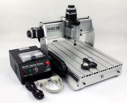
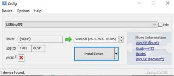
For this week’s group assignment we had to characterize the specifications of our PCB production process on our CNC 3040. The software that we used for milling was Fab Modules and send nc files trough Mach3 software sender.
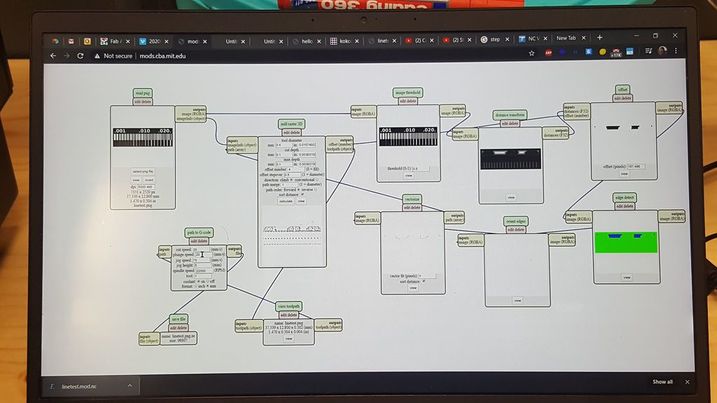
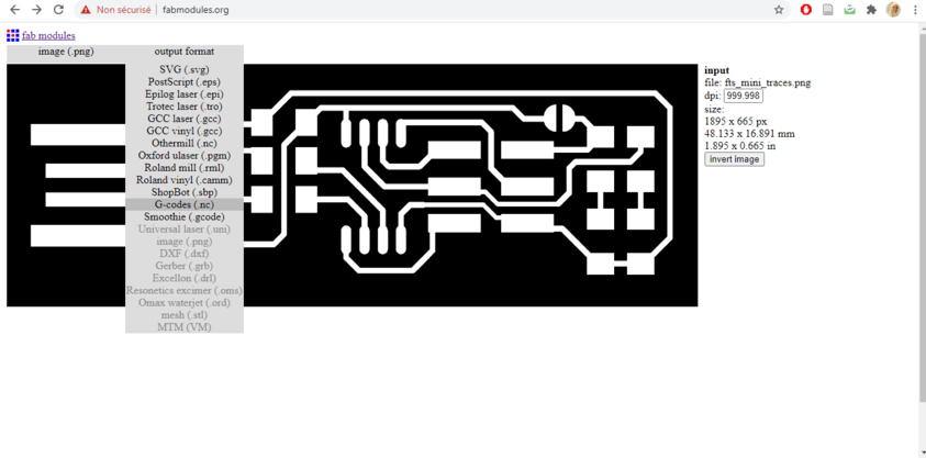
As I said , we used Fabmodules online at mods and we Loaded the image as a png [ we used linetest.png to milling the trices and linetest.interior.png for the outline].
I use to mill the traces with 1/64 (0.4mm)bit (It means that the mill will cut the traces with an end mill with a diameter of 1/64) and to cut the outline with 1.4mm bit
Then we extract the file as .nc and we put it on mach3. Once its in the machine and before you can start milling you need to setup the machine so you must start with:
Preparing a sacrificial plane
Using the double-sided adhesive tape, attach the 20mm MDF plane to the table; then attack the FR1 base on the sacrificial plane
Attaching the milling bit in the collet and make sure it is 2 or 3 mm from the surface of the FR1
Zeroing the Z height, dropping the tip on the plane, making sure that the Z can theoretically get off at least the right amount to be able to mill
Zeroing the X and Y axes starting from the left-bottom side of the FR1 board
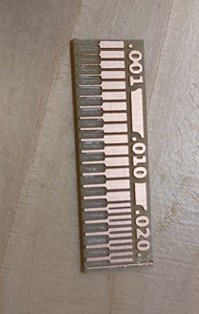
And the result is :
Individual Assignment
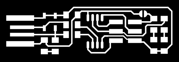
First step to mill the printed circuit board (PCB)was downloading the virtual traces and outline cutout shape of the PCB from the internet in form of .png images with a resolution of 1000 dpi:

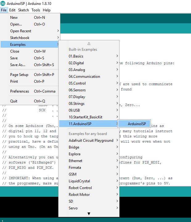
I used used Fabmodules online at Fabmodules to upload the .png images successively and to generate the G-code for the CNC mill to mill the traces and to mill the outline shape of the PCB.
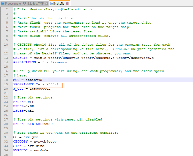
Important settings to consider:
speed (mm/s): (this value can be experimented with and depends on the machine accuracy)
x0 mm: (states the starting origin point for X vector)
y0 mm: (states the starting origin point for Y vector)
z0 mm: (states the starting origin point for Z vector)
zjog mm: (specifies how high will the machine displace in Z vector, while traveling to a different location)
cut depth mm: (0 is used since Z depth is taken from the machine)
tool diameter mm: (depends on the milling tool used)
number of offsets mm: (this value is used if we want to fill the entire board, we use that to avoid any shorts on the USB level)
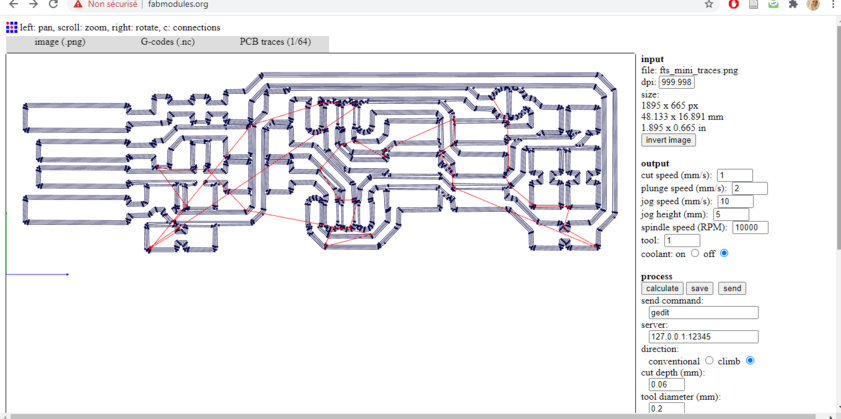
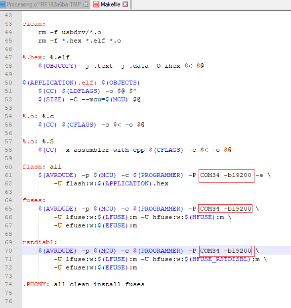
you can notice that the blue lines represent the milling paths, while the red lines the jogs/travels. The .rml file is then saved.
I repeat the process for the outline of the board. This time the PCB Outline 1/32 process is used. Setup settings remain to be the one generated by the website.
The milling
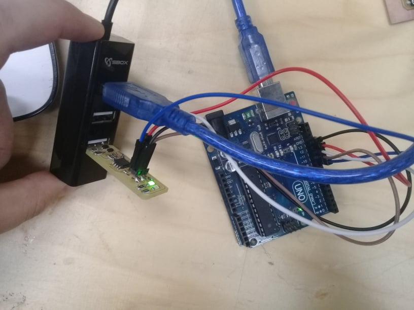
Preparing the milling machine required me to tape carefully the PCB board of the board of the machine and checking well if it would stand flat over it. After turning it on, I moved with the head machine of the machine with its software over the area I desired to start milling, but before pursuing in this operation I had to zero the coordinates and adjust the height of the mill.
In our milling software, there are essentially two ways of moving the head manually: continuosly, for rapid movement across the board, and by steps of ratio 10/100/1000, for slower and more controlled movements. This second option is almost essential for accomplishing the following operation without risk of damaging the drill tip.
Once you’ve chosen the x,y coordinates to start the milling process, you can push the Set X/Y button in the software to zero them. The same operation had to be done for the z, meaning that you have to lower manually (slowly and by heavily controlled steps!) the milling tip over the board and after you’ve reached an height that is just enough, you have to manually un-screw the tip from the spindle, push it slightly over the PCB surface and the screw it back.
This operation has to be done very carefully, especially with 0.4 mm (1/64th of inch ) tips because they’re very fragile and can be damaged with the slightest lack of attention.
After that, you can submit the Set Z command, prompt you RML file to software and initiate the milling process.
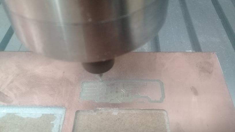
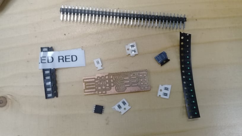
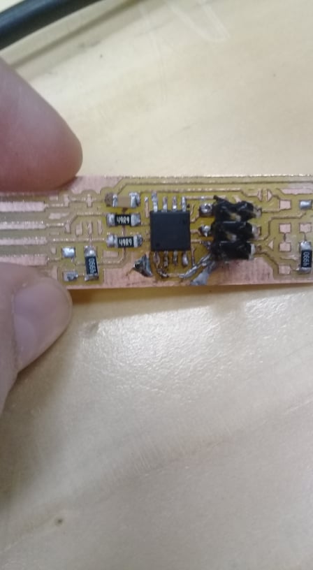
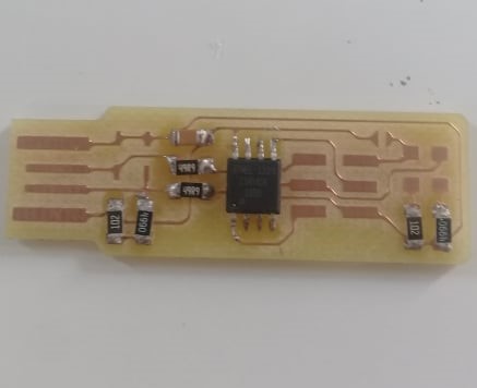
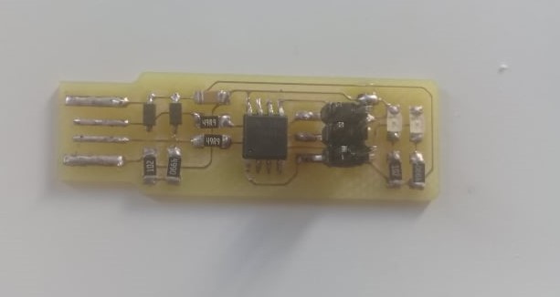
after several times , The board is ready for soldering.