Laser Cutter
The requirement for this assignment was to learn to work with laser cutter as well as produce an object by using the technique of cutting, engraving as well as implement joints between parts.
Group Assignment
Link to the group assignment page
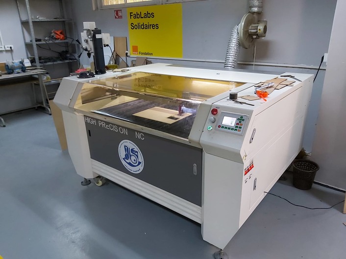
For the assighment groupe, we must characterize the lasercutter's focus, power, speed, rate, kerf, and joint clearance. For this we use the Golden Sign GS9070 which is a class 3R laser cut. It is important to mention that most 'cutting lasers' are Class 3R laser products and have a level of accessible emission up to five times the limits for Class 1 (if invisible) or Class 2 (if visible) .In addition , for this class, lasers are considered safe when handled carefully. There is only a small hazard potential for accidental exposure. For visible-light lasers, Class 3R lasers’ output power is between 1 and 4.99 milliwatts.
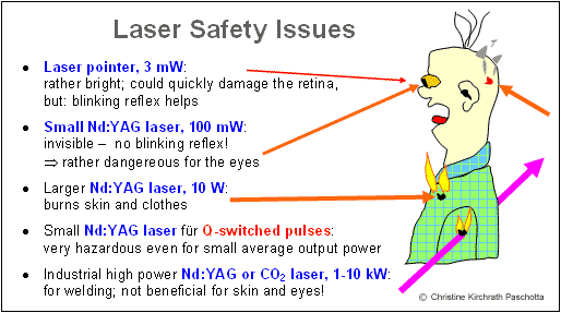
For our group assignment and our first use of the laser cutter machine , I've learned some safety rules which are:
Never leave the laser cutter unattended.
Only cut materials approved by your instructor.
Keep the lid closed at all times, unless loading material while the laser is turned off.
Clean up debris in the laser cutter.
Identify the fire extinguisher and fire blanket
Steps of laser cut preparation:
Lift the lid, insert your material on the honeycomb, and close the lid.
Flip on the power strip and perform 3 checks:Make sure the air compressor is on: listen or touch the machine to make sure it’s running.
Make sure there are no bubbles in the laser tube.
Connect to laser cutter via either a USB or Ethernet cord. Consult your instructor if you have difficulty connecting.
Connect to laser cutter via either a USB or Ethernet cord. Consult your instructor if you have difficulty connecting
Home the laser by hitting the home button on the machine . Homing sends the laser head back to its starting position so that the machine can know exactly where the laser head is while the laser cutter is turned on.
Move laser to where you’d like to start cutting or engraving - by default, the top left corner of the design is the starting location.
Perform perimeter check to ensure the design fits on the material.
And finaly,Adjust the power and speed settings of the machine.
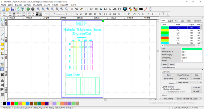
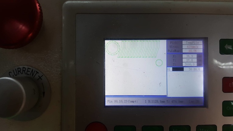
For the laser setting card,we took inspiration from other open source card and we made our own template after, we chose to test cutting and engraving at the same time on MDF 3mm with diffrent speed and laser power for each rectangle test (like shown in the previous image). Then export the sketch to DXf format.
Download:Template DXF,Template AI
we usually use RDworks or LaserCAD to manage and send the job to the laser. The software can set parameters (setting) like power, speed and frequency per color or for the whole job, but only lines thinner than a dpi-dependent threshold are recognized to be cut. Since our template required so many different settings, we had to use multiple colored layers to stack all the power settings. RDworks has a limited number of layers and so it became very time consuming to cut even one template.
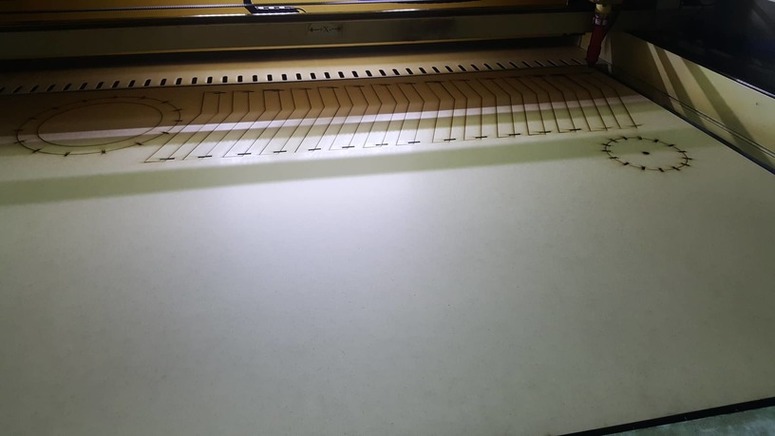
This is the final result of the group assignment:
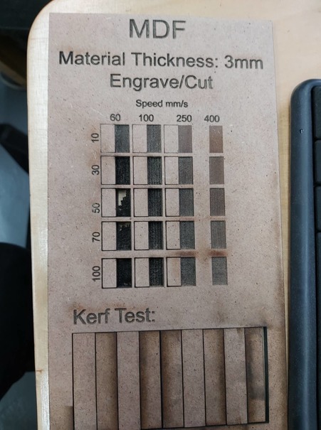
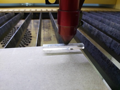
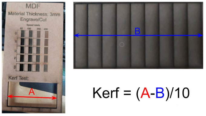
T test the kerf ,which is generally determined by material properties and thickness, the focal length of the lens and the gas used while cutting (only CO2 in our case), we have designed a simple test in order to find a kerf. As in the previous picture we have drawn 9 rectangular pieces (10mm each) for 10 vertical cuts. This for make an average on the long distance. Dividing this gap by ten gives the average kerf for that material and material thickness. In the our case we’ve obtained a 0.3mm kerf for plywood with 3mm thickness.
Individual assignments
Parametric Design
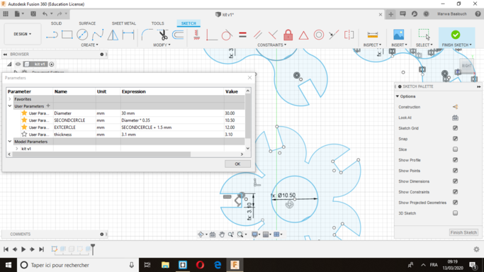
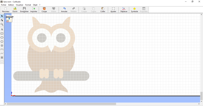
I used fusion to make several designs, I also used wood and cardboard, the first piece was a cardboard kit, I made the parametric design in fusion360 ,in the picture you can see the parameters and you kan change the hole size of the piece because they are releted all together.
Then I exported the file in dxf and I put it on the laser cutting software "LaserCAD".
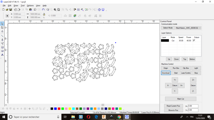
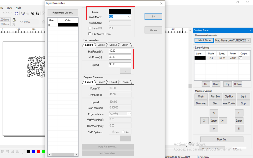
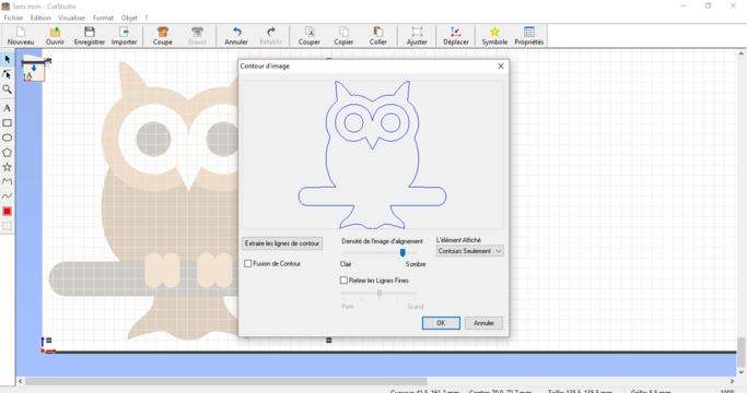
In LaserCAD you must select the outlines that you wish to cut and assign a color from the bottom of the window to each line. Each color corresponds to a group of settings that are set in the upper right window. in my case I have juste to cut my kit so I choose the black color for my setting and I set the cutter speed to 35,and the rate of power to 40.
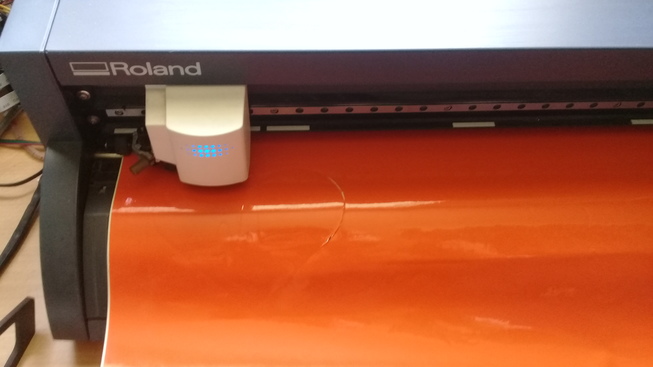
At this point all that is left to do is make sure the computer you are working on is connected to the laser cutter and hit the download command in Laser Cad.
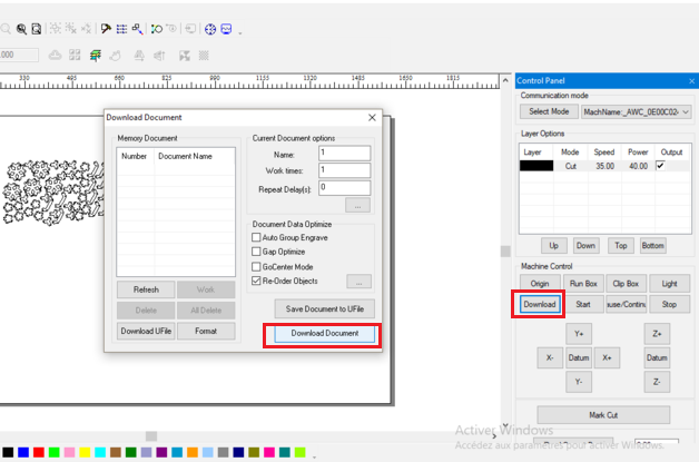
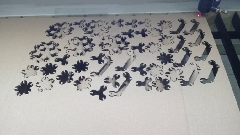
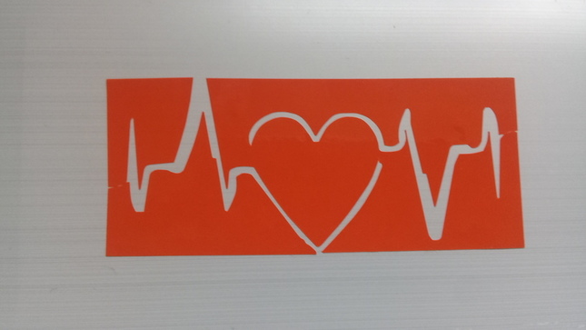
Then fixe the origine ,put the cardboard and start the cutting process.
Download file :fusion file
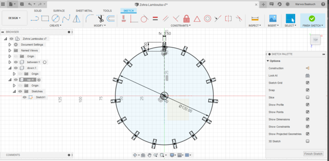
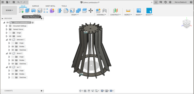
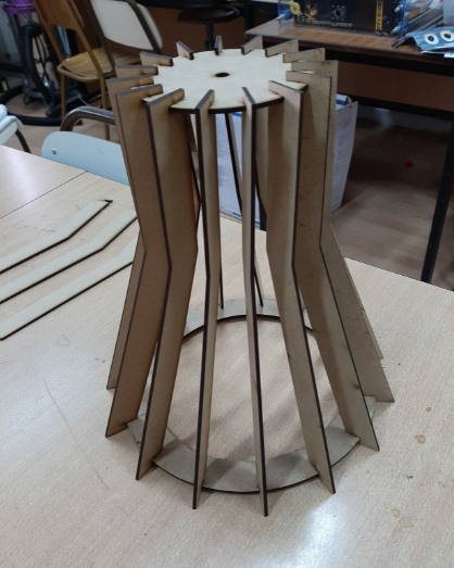
I used the Fusion360 to draw the other pieces too.I have indeed made two other pieces from wood, one to master the parametric design and the other with less details but very useful for me since I need a new lampe :D.
The first design was a pen pot, here are some faces (each two opposite faces are identical) .
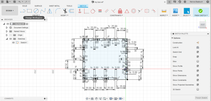
I opened the parameters spreadsheet from Modify → Change parameters and added basic parameters that I will need. For example slotwidth (slotw) ,slotdepth (slotd) etc.
Download file :The fusion file
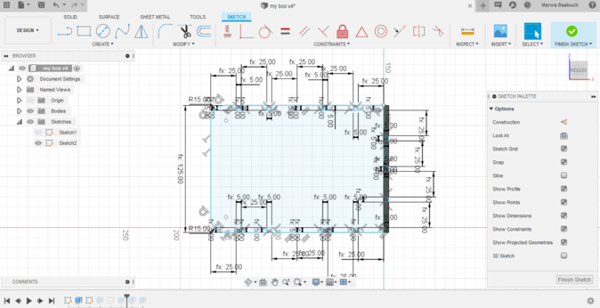
For the second piece , I also do the same job and I extrude it .
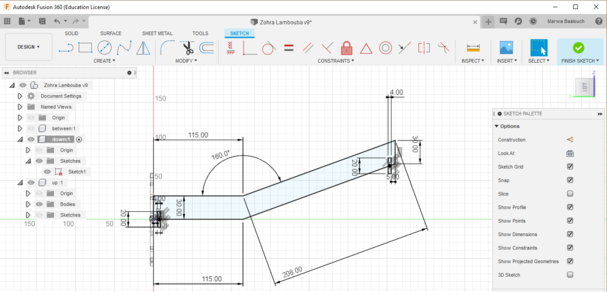
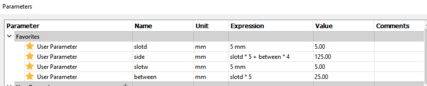
It's important to mention that changing the parameter thickness from 4mm to 12 mm for example changes the other parameters as shown in this picture.
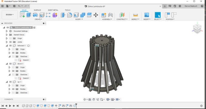
Then I export all the parts
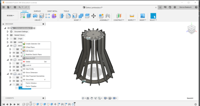
Download file :fusion file
Moving now to the machine, I have send the file to the machine
Then I start working and I've been working on a 3-millimeter MDF
