Group assignment
Link for the group assignment
Individual assignment
A Microcontroller uses many different protocols to communicate with various sensors and peripherals. There are many protocols for wireless and wired communication, and the most commonly used communication technique is Serial Communication. Serial communication is the process of sending data one bit at a time, sequentially, over a communication channel or bus. There are many types of serial communication like UART, CAN, USB, I2C and SPI communication.
In this assignment ,I learn about SPI protocol and how to use it in Arduino. I will use SPI Protocol for communication between two boards.
Serial Peripheral Interface
SPI (Serial Peripheral Interface) is a serial communication protocol. SPI interface was found by Motorola in 1970. SPI has a full duplex connection, which means that the data is sent and received simultaneously. That is a master can send data to slave and a slave can send data to master simultaneously. SPI is synchronous serial communication means the clock is required for communication purpose.
A SPI has a master/Slave communication by using four lines. A SPI can have only one master and can have multiple slaves. A master is usually a microcontroller and the slaves can be a microcontroller, sensors, ADC, DAC, LCD etc. Below is the block diagram representation of SPI Master with two Slaves.
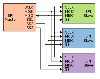
SPI has following four lines MISO, MOSI, SS, and CLK
MISO (Master in Slave Out) - The Slave line for sending data to the master.
MOSI (Master Out Slave In) - The Master line for sending data to the peripherals.
SCK (Serial Clock) - The clock pulses which synchronize data transmission generated by the master.
SS (Slave Select) –Master can use this pin to enable and disable specific devices. During working for this assignment I learned that we need to set the required device's Slave Select (SS) pin to LOW, so that it can communicate with the master. When it's high, it ignores the master.
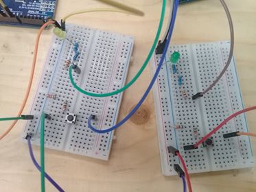
I use two arduino one as master and other as slave. Both Arduino are attached with a LED & a push button separately. Master LED can be controlled by using slave Arduino’s push button and slave Arduino’s LED can be controlled by master Arduino’s push button using SPI communication protocol present in arduino. So I use for this 2 Arduino UNO, 2 leds, 2 Push Buttons ,(2)Resistor 10k, (2)Resistor 2.2k , Breadboard and Connecting Wires. this figure shows how they must be connected.
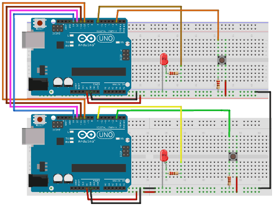
But since I didn't have 10k and 2.2 k resistors at home ,I put resistors in series in order to have the same requested resistance value.
Moving now to the code,this exemple has two programs one for master arduino and other for slave arduino. The code is commented but I will define here the important instructions of the code.
First of all we need to include the SPI library for using SPI communication functions.
Serial.begin(115200); : Start Serial Communication at the same Baud Rate 115200.
SPI.begin();: begin the SPI communication
SPI.setClockDivider(divider) : Set the SPI clock divider relative to the system clock. The available dividers are 2, 4, 8, 16, 32, 64 or 128.
SPI.attachInterrupt(handler) : This function is called when a slave device receives data from the master.
SPI.transfer(val) :This function is used to simultaneous send and receive the data between master and slave.
This is the Master code
#include SPI.h>                             //Library for SPI
#define LED 7
#define ipbutton 2
int buttonvalue;
int x;
void setup (void)

{
  Serial.begin(115200);                   //Starts Serial Communication at Baud Rate 115200

  pinMode(ipbutton,INPUT);                //Sets pin 2 as input
  pinMode(LED,OUTPUT);                    //Sets pin 7 as Output

  SPI.begin();                            //Begins the SPI commnuication
  SPI.setClockDivider(SPI_CLOCK_DIV8);    //Sets clock for SPI communication at 8 (16/8=2Mhz)
  digitalWrite(SS,HIGH);                  // Setting SlaveSelect as HIGH (So master doesnt connnect with slave)
}

void loop(void)
{
  byte Mastersend,Mastereceive;

  buttonvalue = digitalRead(ipbutton);   //Reads the status of the pin 2

  if(buttonvalue == HIGH)                //Logic for Setting x value (To be sent to slave) depending upon input from pin 2
  {
    x = 1;
  }
  else
  {
    x = 0;
  }

  digitalWrite(SS, LOW);                  //Starts communication with Slave connected to master

  Mastersend = x;
  Mastereceive=SPI.transfer(Mastersend); //Send the mastersend value to slave also receives value from slave

  if(Mastereceive == 1)                   //Logic for setting the LED output depending upon value received from slave
  {
    digitalWrite(LED,HIGH);              //Sets pin 7 HIGH
    Serial.println("Master LED ON");
  }
  else
  {
   digitalWrite(LED,LOW);               //Sets pin 7 LOW
   Serial.println("Master LED OFF");
  }
  delay(1000);
}
This is the Slave code
#include SPI.h>
#define LEDpin 7
#define buttonpin 2
volatile boolean received;
volatile byte Slavereceived,Slavesend;
int buttonvalue;
int x;
void setup()

{
  Serial.begin(115200);

  pinMode(buttonpin,INPUT);               // Setting pin 2 as INPUT
  pinMode(LEDpin,OUTPUT);                 // Setting pin 7 as OUTPUT
  pinMode(MISO,OUTPUT);                   //Sets MISO as OUTPUT (Have to Send data to Master IN

  SPCR |= _BV(SPE);                       //Turn on SPI in Slave Mode
  received = false;

  SPI.attachInterrupt();                  //Interuupt ON is set for SPI commnucation

}

ISR (SPI_STC_vect)                        //Inerrrput routine function
{
  Slavereceived = SPDR;         // Value received from master if store in variable slavereceived
  received = true;                        //Sets received as True
}

void loop()
{ if(received)                            //Logic to SET LED ON OR OFF depending upon the value recerived from master
   {
      if (Slavereceived==1)
      {
        digitalWrite(LEDpin,HIGH);         //Sets pin 7 as HIGH LED ON
        Serial.println("Slave LED ON");
      }else
      {
        digitalWrite(LEDpin,LOW);          //Sets pin 7 as LOW LED OFF
        Serial.println("Slave LED OFF");
      }

      buttonvalue = digitalRead(buttonpin);  // Reads the status of the pin 2

      if (buttonvalue == HIGH)               //Logic to set the value of x to send to master
      {
        x=1;

      }else
      {
        x=0;
      }

  Slavesend=x;
  SPDR = Slavesend;                           //Sends the x value to master via SPDR
  delay(1000);
}
}
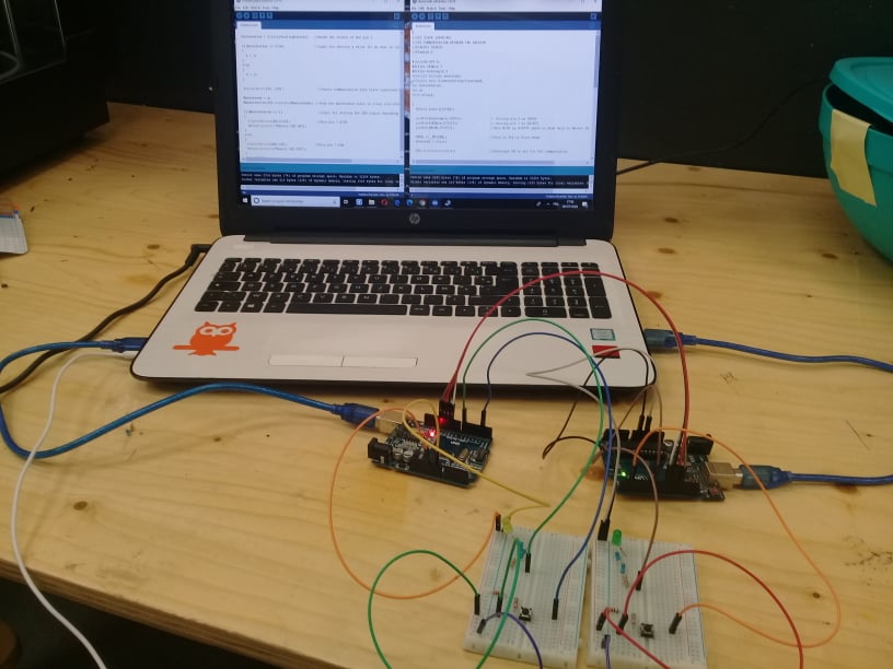
Here you can find the code for both boards ( Master code, Slave code) , noting that we are going to connect both boards to the same pc so we have to choose the exact port to connect with the exact board each time.
As I already said when I introduced the SPI protocol, you can put up to three Slavs. to do this you need :
Choose an SS pin for another slave since the arduino only defends one SS (which is D10), we can take D9 as an SS2 for the second slave.
Initialize it as an output with: pinMode(SS2, OUTPUT);
In the setup function (of the master code) add the instruction : digitalWrite(SS2,HIGH); (So master doesnt connect with slave)
Inthe loop function , when triing to connect with only one slave SS or SS2 use respectivly digitalWrite(SS, LOW); or digitalWrite(SS2, LOW); and also keeping the other SlaveSelect as HIGH.
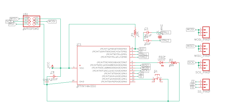
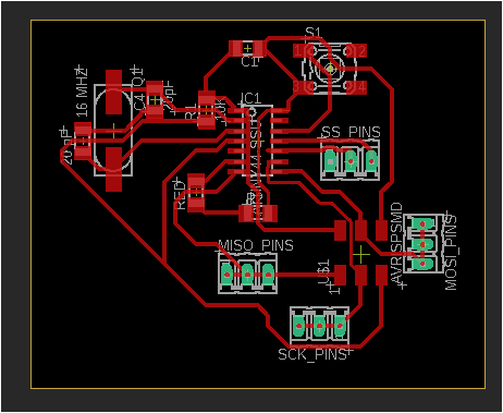
Board design
Moving now to the board,it will support up to 3 slaves since it contains three SS pins, I use avalable pins 5, 10 and 11 in my attiny44 since an INTn or PCINTn interrupt can signal that the Master requests the Slave.
it can play the role of a master or a slave.