Group assignment
Link for the group assignment
Individual assignment
Since we work at home and we don't have access to fablab and tools I will work with an arduino board for this assignment and I will design a dedicated board for him to build it later when we have access to fablab.
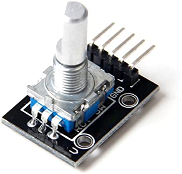
The incremental encoder
For this assignment I will use the Arduino 360 degree encoder (or incremental encoder) as an input device. It's an incremental electromechanical component with a shaft that converts the angular position or motion of a shaft or axle to digital code. The output of incremental encoders provides information about the motion of the shaft, which is typically further processed in processor / controllers into information such as speed, distance, and position.The shaft has unlimited 360 degree rotation.
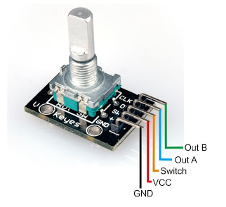
Rotary encoders don’t output an absolute, fixed position, but rather have a number of increments per 360 degrees, and each increment consists of digital pulses known as ‘grey code’. Well as it turns out, reading gray code is actually quite simple. There is a common pin which connects to ground, then an A and a B pin which carry your signal.
When the rotation to the next increment begins, you can see either the A (clockwise) or B (counter-clockwise) channels fall, then the other follows, then the leading pin rises again, followed by the other pin.
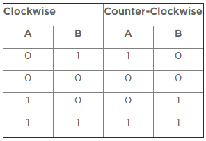
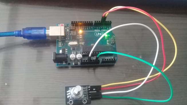
As I said at the beginning, both pins are held high when there is no rotation, then if we monitor the state of both pins, as soon as one falls low, we compare the other pin, and if it is still high, that means a rotation has begun, and we can determine the direction by which pin was pulled low first. To test that I connect the encoder to arduino with 4 wires :
CLK : Pin A to D3
DT : Pin B to D4
+ : Power to 5V
GND : Grounding to GND
I didn't use the push switch that why I didn't connect the SW pin to my arduino. and then I connectthe arduino tp the PC as mentioned here
This is the code that will let you count rotations when I rotate the shaft
int pinA = 3;
int pinB = 4;
int encoderPosCount = 0;
int pinALast;
int aValue;
boolean CW;

 void setup()
 {
  //here I put pinA and pinB as input
   pinMode (pinA,INPUT);
   pinMode (pinB,INPUT);
   pinALast = digitalRead(pinA);// thos instruction will read from pinA
   Serial.begin (9600);
   Serial.println("start");
   Serial.println();
 }

 void loop()
 {
   aValue = digitalRead(pinA);
   if (aValue != pinALast)
   {
     if (digitalRead(pinB) != aValue) //here if this condition is verified that means that we're Rotating Clockwise
     {
       encoderPosCount ++; // encoderPosCount= encoderPosCount +1 ( count the additional position )
       CW = true;
     }

     else

     {
       CW = false;
       encoderPosCount--;// encoderPosCount= encoderPosCount -1
     }

     if (CW)
     {
       Serial.println ("Rotate Clockwise");
     }

     else

     {
       Serial.println("Rotate Counterclockwise");
     }

     Serial.print("Encoder Count: ");
     Serial.println(encoderPosCount);
     Serial.println();
   }

   pinALast = aValue;
 }
Download code
This video shows the test
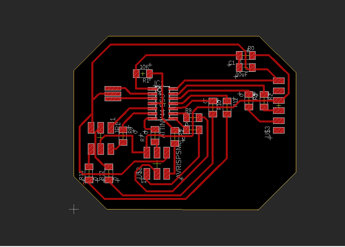
Board Design
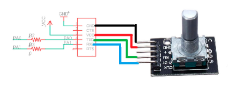
the circuit includes a Attiny44, the connections to an FTDI communication and the ports needed to program it, the connection with the encoder is as follows :
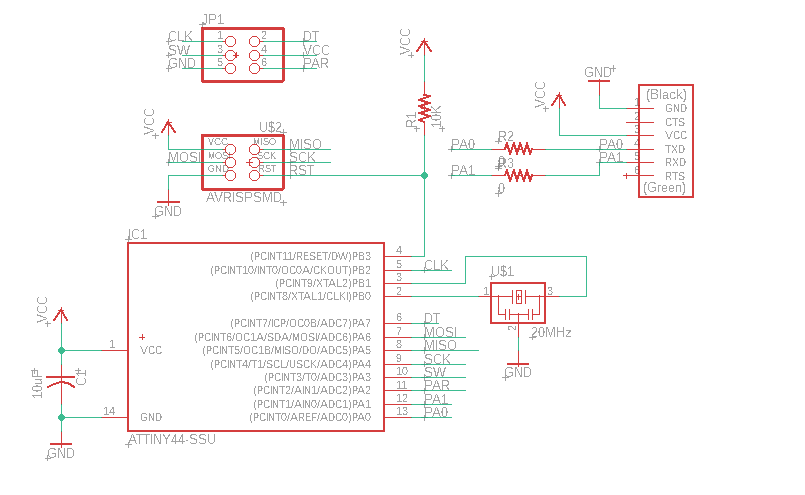
Here I need to add resistors of 0 Ohm, to create a lot of bridges, it helps a lot since it seemed impossible to me without bridges or other layers.