11. Output devices
What I’ve done this week
- chose an output device and design and make PCB for it.
Weekly Assignment Requirement
Individual assignments
- add an output device to a microcontroller board you’ve designed, and program it to do something
Group assignment
- measure the power consumption of an output device
Description of Assignment Work
The topic of this week was the output device. Though Neil introduced many kinds of devices in his lecture, I picked RGB LED which directly related to my final project.
Above all, I used NeoPixel which included IC chip for controlling the value of RGB by serial communication. The reason I used was that it needed only one pin for communication even if I used some of lights and of course easy to control them as well.
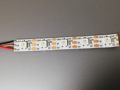
there are three terminals for input on the one side. Two of them are 5V and GND for power supplying. the rest of them in the middle is for signals to communicate. and the ones for the output are on the other side. it designed to use as a sequence easily so it is okay to solder only first input terminals for using.
Preparation to use NeoPixel on ESP32
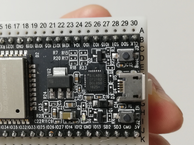
I had already decided to use the ESP32 based MCU board for my final project by this time. So I chose to rent a ESP32 dev board from FabLab Kamakura for this week’s assignment.
Firstly, I set up for a ESP32 dev board on Arduino IDE.
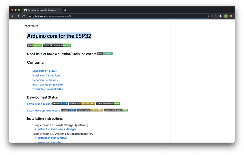
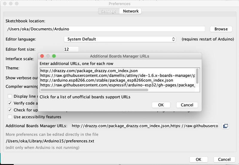
I downloaded the Arduino core for the ESP32 from the github
and added to the IDE using board manager.
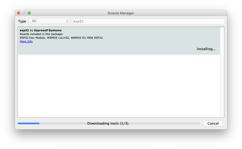
I could find the board on the list.
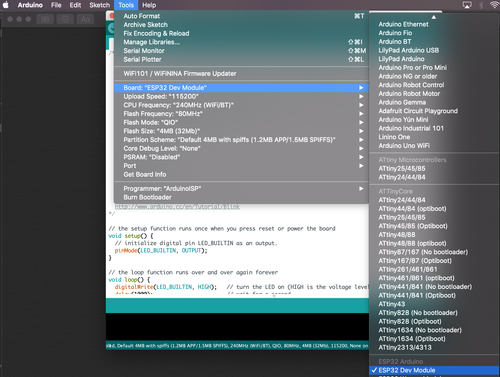
but I couldn’t find the port where it should have shown up.
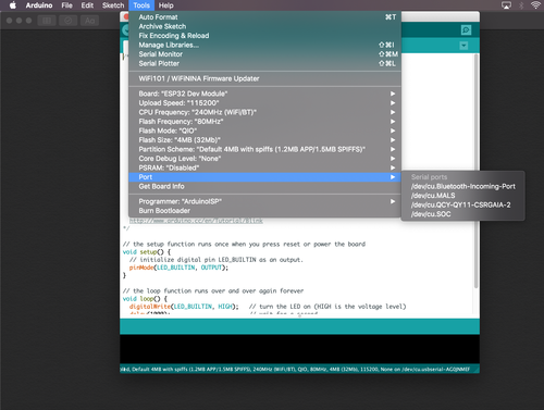
I researched online to solve this problem for a while. Then I found the answer which said that the ESP32 dev board needed driver for CP2102 which was used for serial communication on the dev board.
I downloaded CP201x VCP Driver immediately and set up.
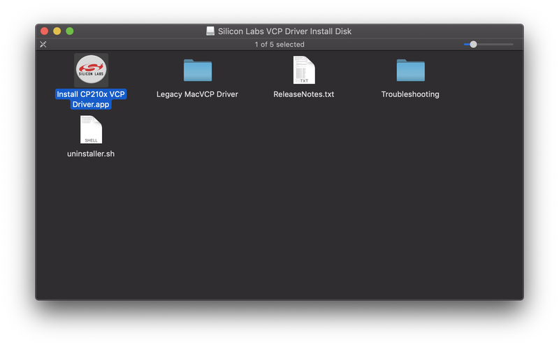
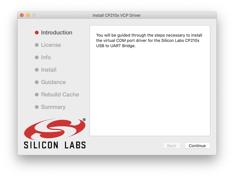
It worked as I expected so setting up had been done.
First try
I simply started to try the library for the Neopixel which was developed by adafruit. It also included lots of sample program so I picked the one called simple. This sample code only required to change the pin number assigned to Neopixel and the number of the Neopixels I used with this. the color of it would be changing seamlessly like a rainbow. but I just wanted to check to turn on LED so I set the green color on it. I put actual code below.
// NeoPixel Ring simple sketch (c) 2013 Shae Erisson
// Released under the GPLv3 license to match the rest of the
// Adafruit NeoPixel library

#include <Adafruit_NeoPixel.h>
#ifdef __AVR__
 #include <avr/power.h> // Required for 16 MHz Adafruit Trinket
#endif

// Which pin on the Arduino is connected to the NeoPixels?
#define PIN        32 // On Trinket or Gemma, suggest changing this to 1

// How many NeoPixels are attached to the Arduino?
#define NUMPIXELS 2 // Popular NeoPixel ring size

// When setting up the NeoPixel library, we tell it how many pixels,
// and which pin to use to send signals. Note that for older NeoPixel
// strips you might need to change the third parameter -- see the
// strandtest example for more information on possible values.
Adafruit_NeoPixel pixels(NUMPIXELS, PIN, NEO_GRB + NEO_KHZ800);

#define DELAYVAL 500 // Time (in milliseconds) to pause between pixels

void setup() {
  // These lines are specifically to support the Adafruit Trinket 5V 16 MHz.
  // Any other board, you can remove this part (but no harm leaving it):
#if defined(__AVR_ATtiny85__) && (F_CPU == 16000000)
  clock_prescale_set(clock_div_1);
#endif
  // END of Trinket-specific code.

  pixels.begin(); // INITIALIZE NeoPixel strip object (REQUIRED)
}

void loop() {
  pixels.clear(); // Set all pixel colors to 'off'

  // The first NeoPixel in a strand is #0, second is 1, all the way up
  // to the count of pixels minus one.
  for(int i=0; i<NUMPIXELS; i++) { // For each pixel...

    // pixels.Color() takes RGB values, from 0,0,0 up to 255,255,255
    // Here we're using a moderately bright green color:
    pixels.setPixelColor(i, pixels.Color(0, 150, 0));

    pixels.show();   // Send the updated pixel colors to the hardware.

    delay(DELAYVAL); // Pause before next pass through loop
  }
}
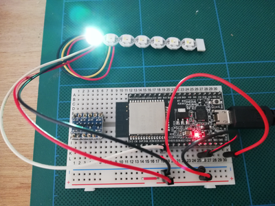
Only first LED was on and its color was not green which I had set in the code. If the program had run properly, two Neopixels should have been turned on greenly.
Second try
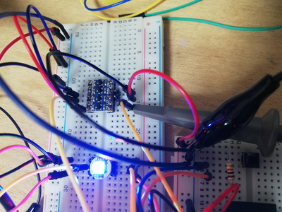
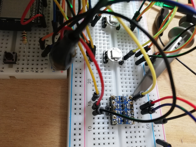
Then, I tried to solve the issue above. For making Neopixels convenient to debug, I remake them like dividing them into pieces and attaching pin-legs for each terminals to put them breadboard easily.
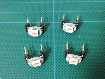
Another reoson I made them was that it could be useful for deciding the position of LEDs in my final project after debugging.
logic level converter
My mentor adviced me that ESP32 sent signals of 3.3V and Neopixels required more than that (VI:-0.5〜VDD+0.5). So I was given logic level converter from him for rising voltage of signals.
the converter had pins on its two edges. the one side used for input from 3.3V and the other side from 5V likewise. Not only signal lines but also 5V and GND had to be connected to it. signal could be passed bidirectionally so this time it would come from 3.3V to 5V.
I checked signals via oscilloscope.
picked the V from before through the converter
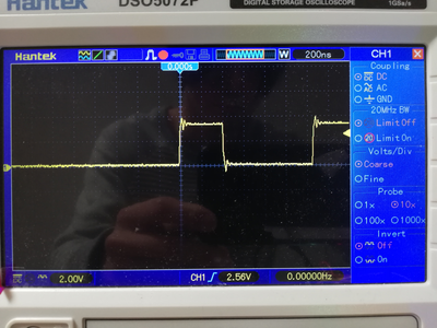
V was indicated around 3.5V
picked the V from after through the converter
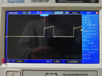
V was reached to 4V at the end of its signal. it seemed weak but worked somehow.
the signals seemed okay but still not working properly.
worked with RGBW setting
I still had problem at that time. but when I see the light pattern, I gradually recognized the color of light seemed slided from where it should be.
and then I found that it was the RGBW LED and I should add the value for White adding to RGB parameter.
There might be some of the way to write the code for RGBW neopixel. I changed the code like the following.
pixels.setPixelColor(i, pixels.Color(0, 150, 0));

↓

pixels.setPixelColor(0, 0, 0, 150, 0);
and whole code was like this
#include <Adafruit_NeoPixel.h>
#ifdef __AVR__
#include <avr/power.h> // Required for 16 MHz Adafruit Trinket
#endif

// Which pin on the Arduino is connected to the NeoPixels?
#define PIN        32 // On Trinket or Gemma, suggest changing this to 1

// How many NeoPixels are attached to the Arduino?
#define NUMPIXELS 2// Popular NeoPixel ring size

// When setting up the NeoPixel library, we tell it how many pixels,
// and which pin to use to send signals. Note that for older NeoPixel
// strips you might need to change the third parameter -- see the
// strandtest example for more information on possible values.
Adafruit_NeoPixel pixels(NUMPIXELS, PIN, NEO_GRBW + NEO_KHZ800);


#define DELAYVAL 500 // Time (in milliseconds) to pause between pixels

void setup() {
  // These lines are specifically to support the Adafruit Trinket 5V 16 MHz.
  // Any other board, you can remove this part (but no harm leaving it):
#if defined(__AVR_ATtiny85__) && (F_CPU == 16000000)
  clock_prescale_set(clock_div_1);
#endif
  // END of Trinket-specific code.
  Serial.begin(115200);
  pixels.begin(); // INITIALIZE NeoPixel strip object (REQUIRED)
  pixels.show();            // Turn OFF all pixels ASAP
  pixels.setBrightness(50); // Set BRIGHTNESS to about 1/5 (max = 255)
}

void loop() {
    pixels.clear(); // Set all pixel colors to 'off'
    pixels.setPixelColor(0, 255, 165, 0, 0);
    pixels.setPixelColor(1, 255, 165, 0, 0);
    pixels.setPixelColor(2, 255, 255, 50, 100);
    pixels.setPixelColor(3, 255, 255, 50, 100);
    pixels.show();   // Send the updated pixel colors to the hardware.
}
this time worked perfectly!
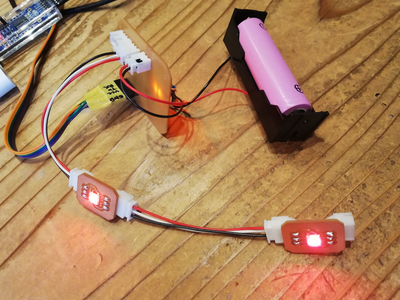
Design the Modular Board for final project
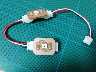
Under the influence of covid-19 I couldn’t cut PCB board for a while. I was just thinking that I would make the modular PCB board for my final project. As I mentioned on week09, I would make mainboard with MCU and also make peripheral boards including the output device for it to organize modular system. So for the assignment of this week, I designed and cut the small PCB of Neopixel.
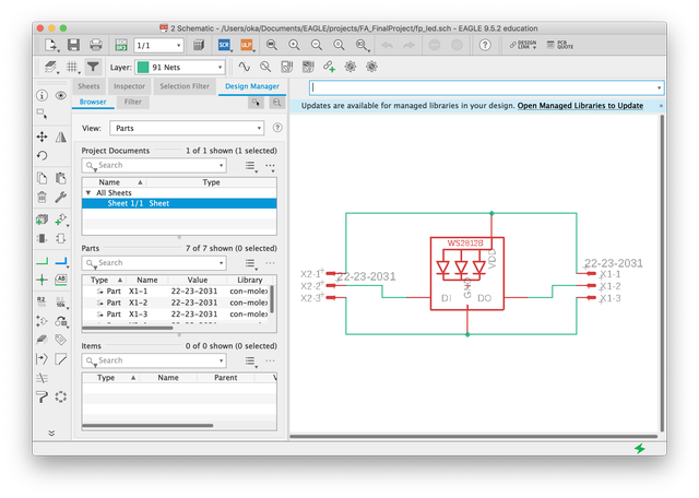
I changed the Neopixel from the one I tested with ESP32 DEV board. The old one needed a logic level converter to manipulate it accurately. But I found another new Neopixel WS2812B-V5 which even worked with signals of 3.3V according to its datasheet. So I chose it and tried make PCBs of Neopixel for my final project.
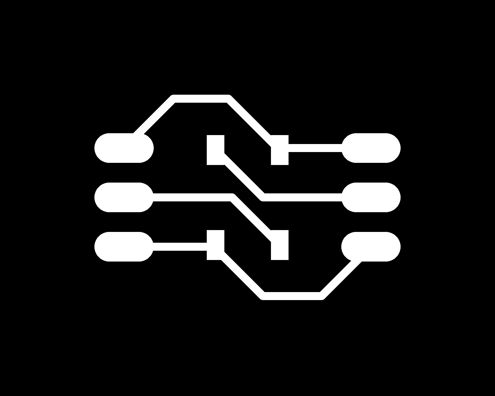
Here was a board design
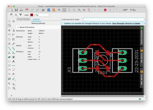
the actual board
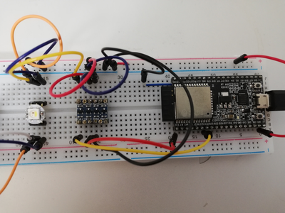
Failed at first test with the ESP32 DEV. Because I tried testing with the code for RGBW. I changed RGB LED so changed the code.
here is new code
#include <FastLED.h>

#define LED_PIN     32
#define NUM_LEDS    2

CRGB leds[NUM_LEDS];

void setup() {

  FastLED.addLeds<WS2812, LED_PIN, GRB>(leds, NUM_LEDS);

}

void loop() {

  leds[0] = CRGB(255, 0, 0);
  leds[1] = CRGB(255, 0, 0);
  leds[1] = CRGB(0, 120, 0);
  FastLED.show();
  delay(3000);
  leds[0] = CRGB(0, 0, 120);
  leds[1] = CRGB(0, 0, 120);
  FastLED.show();
  delay(3000);
}
succeeded! Previously I used Adafruit_NeoPixel.h library but changed to FastLED library and worked well. It seemed to be easier to use than the previous one in terms of simplicity of the code.
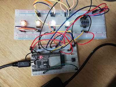
worked with my FP board as well!
Group Assignment
Checked the power consumption of my MCU board and Neopixel board by multimeter.
Please see the link below.
Kamakura Group assignment week11
Description of Important Weekly Learning Outcome
I played around with RGB LED this week. It had seemed very simple and expected super easy to use. But there were some really tricky points like voltage of signal and the type of color controlling so it took time a lot actually. I thought it gave me the oppotunities to do debug the stuff I made. to look for broblem in my own work was a kind of interesting in a way and also absolutely fun when I solved it. For me, this LED things was a realy nice for the gate to experience the whole process from development to debugging in comparison to the other complicated devices.
Links to Files and Code
Eagle sch (.sch)
Eagle brd (.brd)
Traces(.png)
Outline(.png)
Holes(.png)
Traces cutting data (.rml)
Outline cutting data (.rml)
Holes cutting data (.rml)
Appendix
About NeoPixel(Japanese source)