Final Project
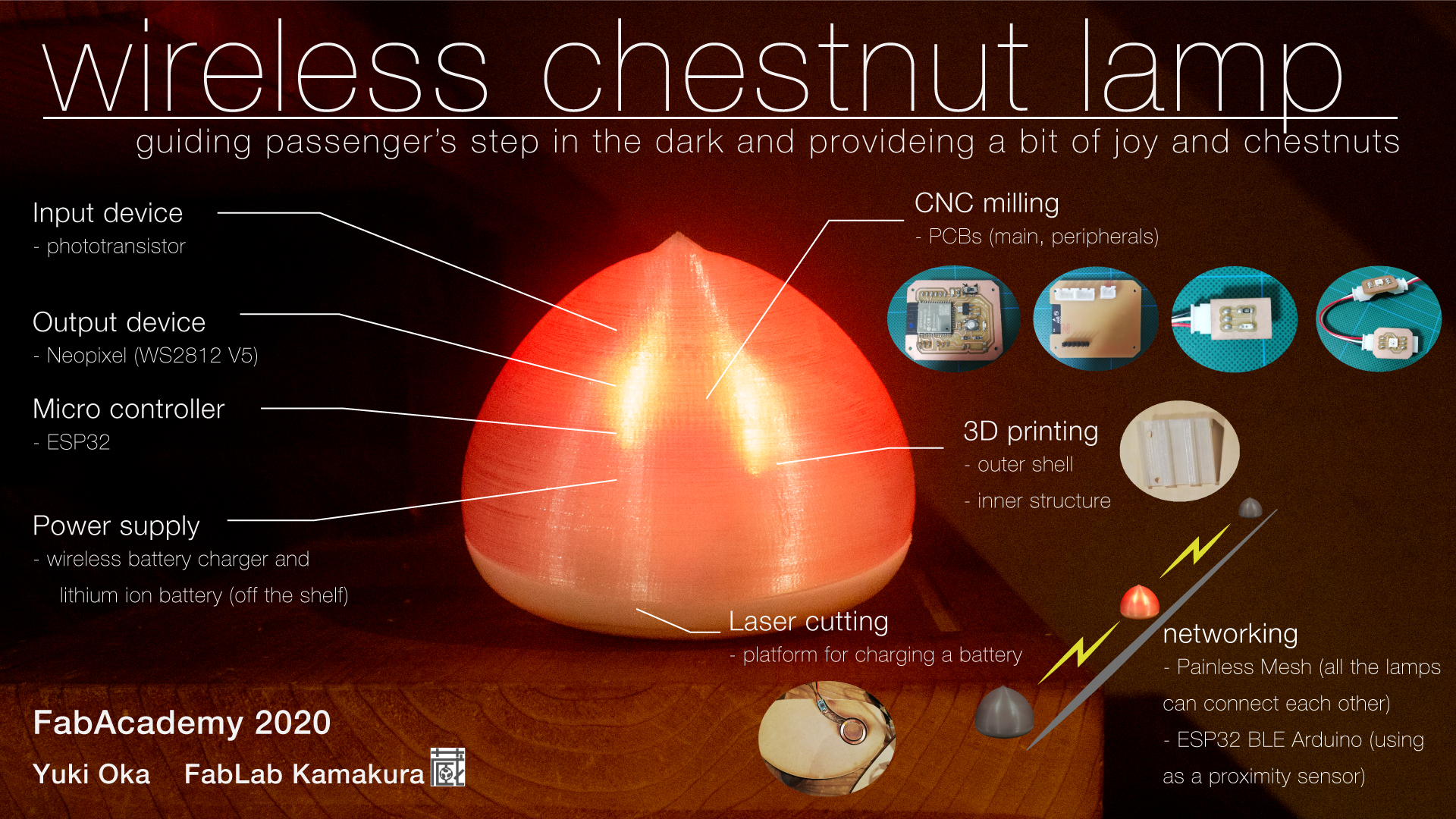
wireless chestnut lamp
created by Yuki Oka
Visual of the outcome
Video for the presentation
Concept
My hometown has lots of farm roads along fields. It is useful cause it could be shortcut rather than taking a wide national route. But in the evening, the road seems really dangerous to go through especially you are not accustomed to it because there are no light. So I planned to create portable lamp to put them along the farm roads. It must be great help that people walk through safely in the nighttime. The shape of it symbolizes a chestnut because the name of my hometown is named after it.
And I add networking system to the lamps to control the combination of them. By this system, I can use them to create illumination show. It changes the depressed darkness to the enjoyable space. So I set the catch phrase “guiding passenger’s step in the dark and providing a bit of joy and chestnut”.
I want anyone to use my product freely because it help to increase the publicity of my project and my hometown and also not to dominate the right for commercial right. So I set Attribution-ShareAlike CC BY-SA for this project.

What does it do?
The lamp includes the input device and the output one and micro controller to manipulate them. This time, I use ESP32 for micro controller of the device to create the network among several devices. For the input one, I use a phototransistor which detects darkness and the device is controlled to be activated only in the dark. And also ESP32 works like sensor as using the strength of BLE connection like proximity sensor. It detect the length between the lamp and the person who has the BLE tag (I prepare another ESP32 for this.) For the output device, I use Neopixel to control light color and volume easily with using less number of pin of ESP32.
Who’s done what beforehand?
-
JEWL by Casper Koomen
It was a wearable accessory that can change its color to match his/her outfit.
The shape of it was quite similar to my idea. It might be helpful for considering the balance of structure between the shell of the body and the electronics (especially LED) inside. -
IoT Lighting system by Perttu Piirainen
It was a smartphone controllable WiFi based on an RGB lighting system(using LED strip, ESP32, and Blynk app).
The controlling LED system of it could be used for mine. So it seemed useful.
Techniques I used for the project
here, I wrote down the fabrication skills, machines, and application I used.
Designing
I used Fusion360 for making 3D model of the project mainly. almost all the thing was designed by Fusion360 this time. but sometimes I also used 2D design software to help creating actual model like the time using laser cutter. And I felt hand drawing skill was important while planning my final project.
▼related keywords
Fusion360, illustrator, photoshop
3D printing
I used 3D printing for making body and even small parts like button and clip for the small parts inside the body.
Before I experience the FP term, I only used Affinia 400 with ABS filament.but this time I used Anycubic with PLA and ultimaker cura as a slicer. it was surprisingly easy to use for me. especially PLA is not so much shrink compared to ABS. I really liked it.
▼related keywords
ultimaker cura, Anycubic, PLA
Laser cutting
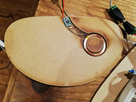
I used laser cutting for the partition of inside the body and platform for the devise. I had to set the wireless charger hiding from user so I engraved MDF by laser cutter and sanded it for the parts fitting inside.
the software controlling laser cutter in FabLab Kamakura was Corel Draw so I used it slightly.
▼related keywords
trotec 100, illustrator, Corel Draw
CNC milling
I used SRM20 for cutting PCBs. I cut 3 types of board this time. every time I prepared data by mods and then using it on Modera Player4 to control SRM20.
▼related keywords
mods, SRM20, MODELA Player4
Electronics
I always designed the PCB by Eagle. I did 3 kinds of board design. And I used the function converting data from Eagle to Fusion360. for accurate modeling. and when I design the board loaded ESP32, its foot print was too narrow to cut it directly on SRM20 so I edited exported png data on Photoshop.
I used phototransistor as an input device and Neopixel as an output device.
▼related keywords
Eagle, Fusion360, Photoshop, ESP32, phototransistor, Neopixel
Programming
I used Arduino IDE to load the program onto ESP32. And I used the library called ESP32-BLE-Arduino to make an proximity sensor using BLE function. And used PainlesMesh library to construct mesh network between the devices.
When I tried to use ESP32-BLE-Arduino, the extra volume of ESP32 was not enough so I changed setting via spreadsheet to get the room from another function(which is used for auto update of Arduino program)
▼related keywords
Eagle, Fusion360, Photoshop, ESP32, phototransistor, Neopixel
BOM
| unit | part | description | quantity | where | cost |
|---|---|---|---|---|---|
| Main Board | micro controller | ESP32 | 1 | FabLab Kamakura | |
| 3.3V1A regulator | ADP3338AKCZ-3.3 | 1 | Akiduki denshi | ¥300 | |
| pins | 1×6 | 1 | FabLab Kamakura | ||
| capacitor | 10μF | 2 | FabLab Kamakura | ||
| capacitor | 0.1μF | 1 | FabLab Kamakura | ||
| resistor | 100Ω | 2 | FabLab Kamakura | ||
| resistor | 10KΩ | 1 | FabLab Kamakura | ||
| LED | any color | 2 | FabLab Kamakura | ||
| slide switch | 1 | FabLab Kamakura | |||
| tacktile switch | 1 | FabLab Kamakura | |||
| XH connector | 3pin | 2 | FabLab Kamakura | ||
| XH connector | 2pin | 1 | FabLab Kamakura | ||
| Input Board | phototransistor | PT15-21C-TR8 | 1 | FabLab Kamakura | |
| resistor | 10kΩ | 1 | FabLab Kamakura | ||
| XH connector | 3pin | 1 | FabLab Kamakura | ||
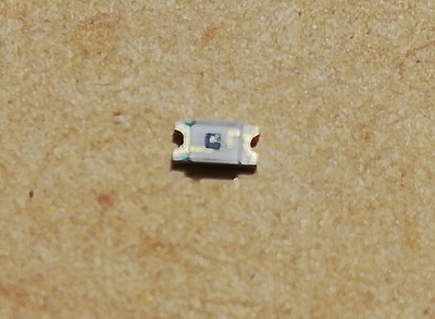
| Output Board | NeoPixel RGB | WS2812B-V5 | 2 | Peace Corporation | ¥60 |
| XH connector | 3pin | 4 | FabLab Kamakura | ||
| Cable | wire | black | 1 | FabLab Kamakura | |
| wire | red | 1 | FabLab Kamakura | ||
| wire | white | 1 | FabLab Kamakura | ||
| Battery | lithium rechargeable battery | 3.7v 1100mAh 1.5A | 1 | Vivan-Star | ¥441.25 |
| wireless chager module | 12V to 5V 1A | 1 | Waves | ¥1380 | |
| Switching power adopter | 12V2A AD-D120P200 | 1 | Akiduki denshi | ¥900 | |
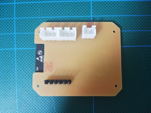
| Base | MDF | 3mm | 1 | FabLab Kamakura | |
| MDF | 5mm | 1 | FabLab Kamakura | ||
| Body | PLA filament | white 1.75mm | 1 | Pxmalion | ¥1999 |
| PLA filament | transparent 1.75mm | 1 | Pxmalion | ¥3080 | |
| MDF | 2.5mm | 1 | FabLab Kamakura | ||
| alternate switch | 1 | FabLab Kamakura | |||
| MDF | 5mm | 1 | FabLab Kamakura | ||
| Total cost | ¥8160.25 |
Design and Fabrication
3D design
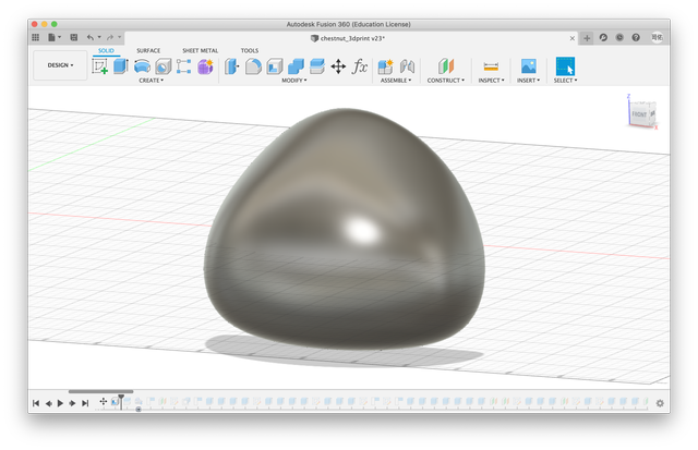
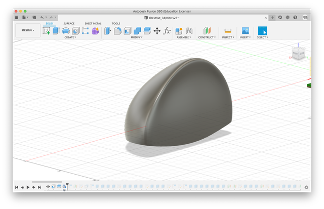
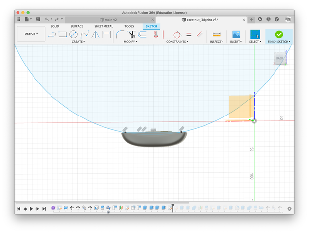
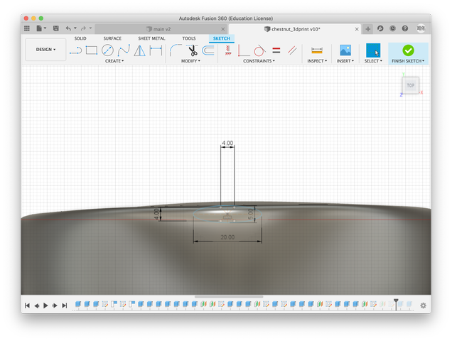
Using fusion360, I tried to create the 3D model resembling chestnut. I used sculpt mode to make. It allowed me to control the shape instinctively. I decided its shape roughly at first.
After finishing rough shape, it had to be divided into two parts. To do so, I created s dish like shape to make curve line on the edge of each part.
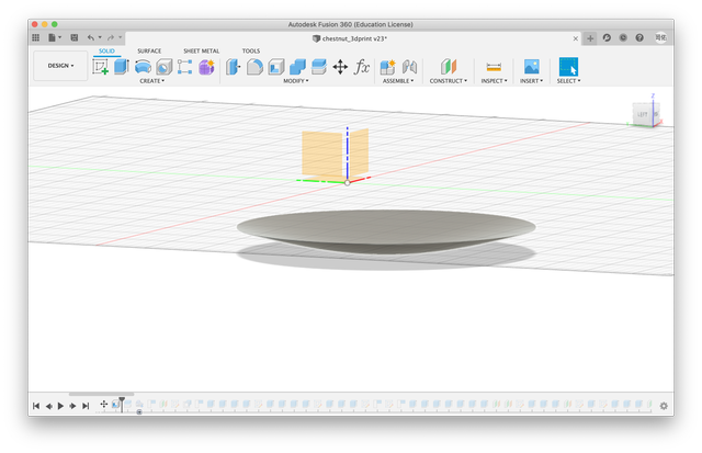
And I took split command to cut the body. It enable to split it by the line made of the dish shape.
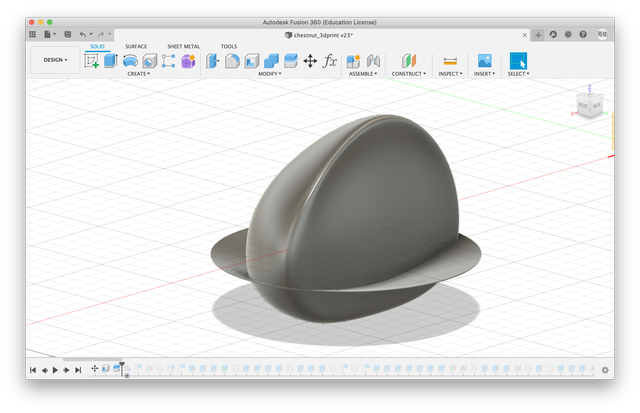
The body was divided into two parts by the command successfully.
Top part
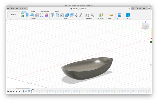
Bottom part
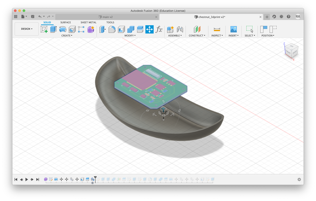
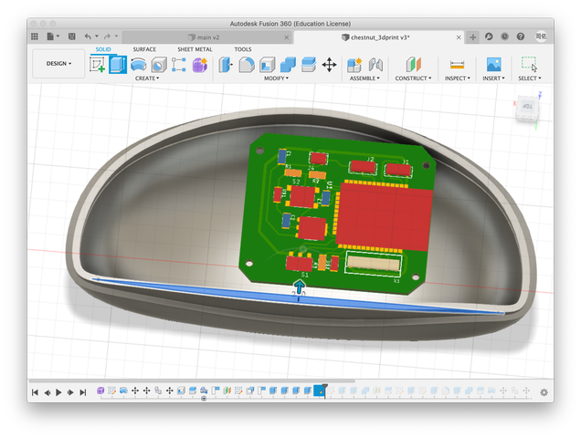
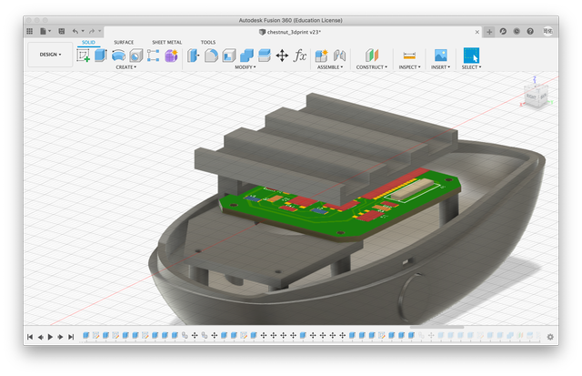
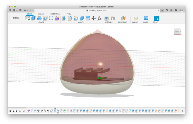
To know the size of the inside structure, I tried to road the main PCB (I would describe it later.) on my 3D model from EAGLE. EAGLE had a function to export the 3D model of the PCB to Fusion360 directly.
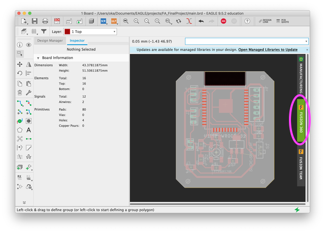
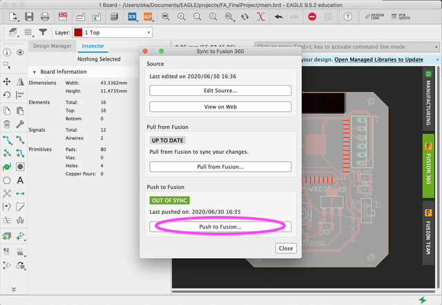
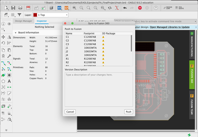
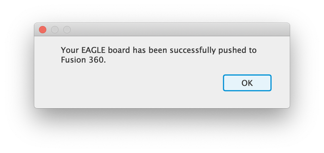
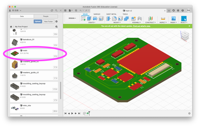
The 3D model of the main board was listed on Fusion360.
Right click and selected “Insert into Current Design”
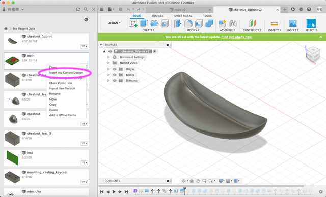
The main board was successfully loaded.
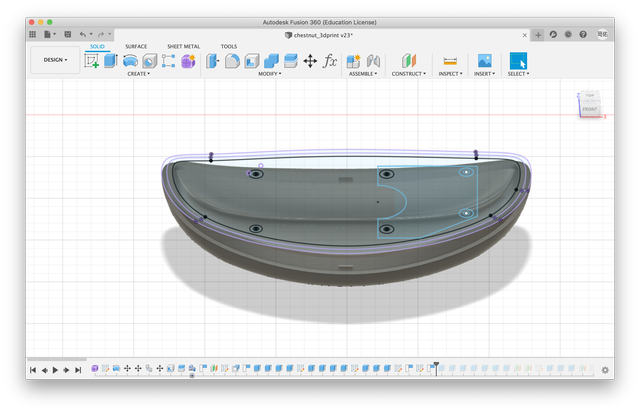
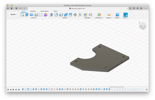
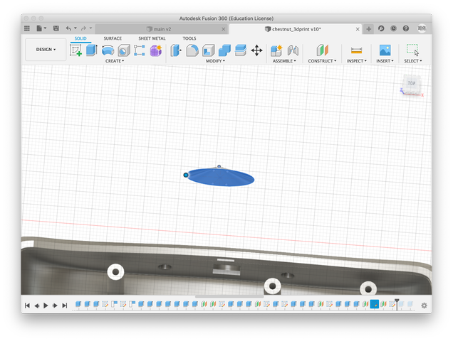
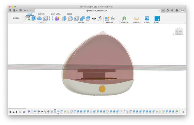
Then, I tried to make the joint between top and bottom part. Firstly, I made the inside wall on the bottom body.
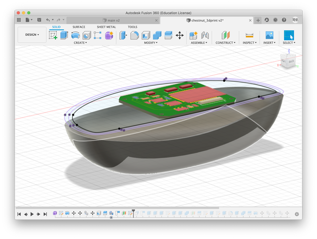
The inner wall seemed to take too much space. So I cut some from it like the edge of it drawing gentle curve.
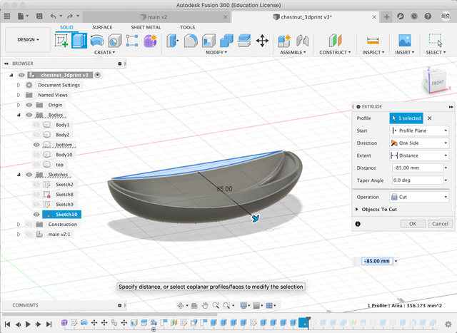
After making inner wall, I made the holes for the joint. And I also made overhang on top part to hitch the whole on the bottom.
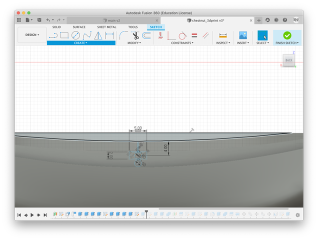
And also I created the parts to help packaging.
Firstly, I made pillars to attach the main board.
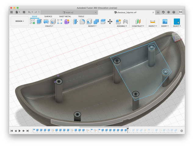
And, I added the board for arranging parts inside.
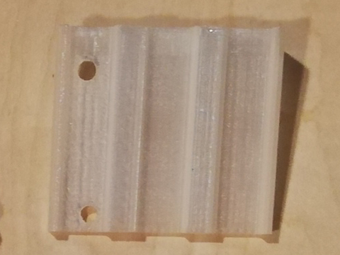
I designed a clip to hold the input board and the output one. It used attaching to the main board.
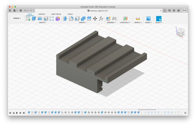
I created the space for the power button. I used an alternate switch for it.
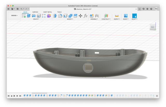
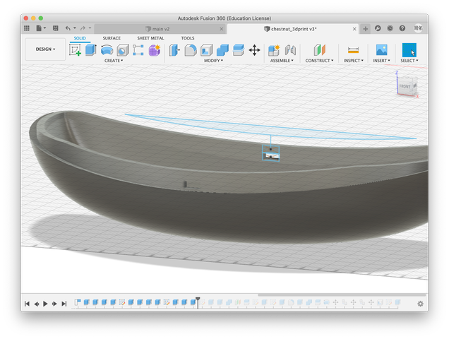
assembled image of the bottom part.
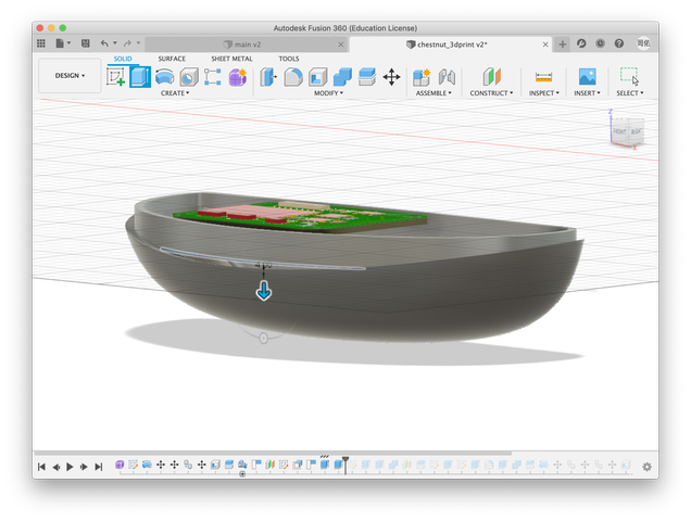
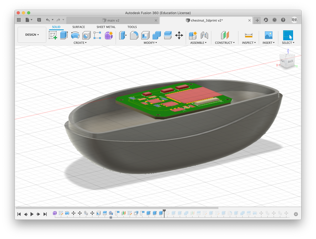
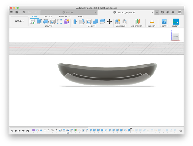
Lastly I add a little decoration on the top part. I created sharp point part on top by using loft command.
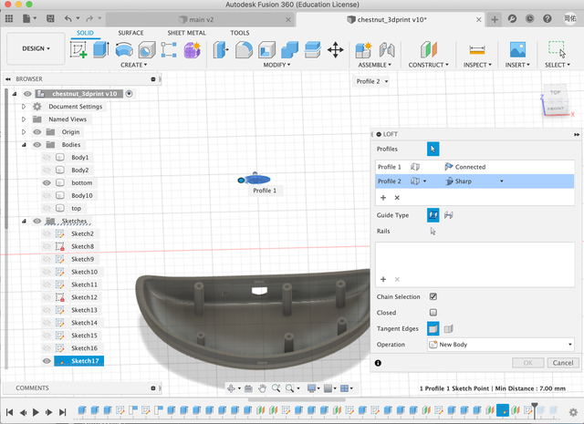
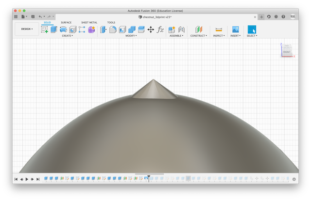
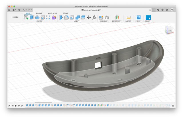
3D modeling have done. Here was the simulated image.
Main board
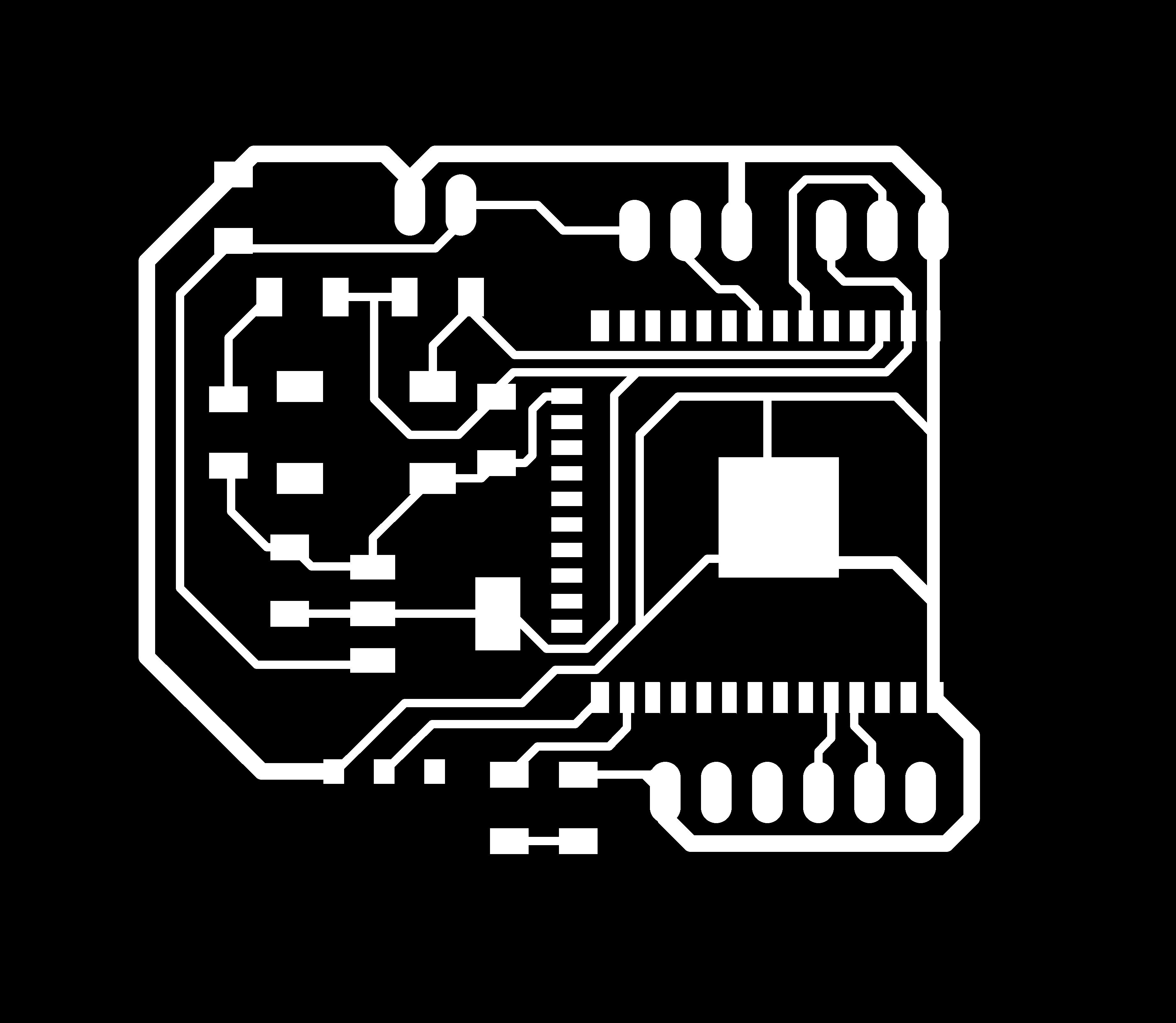
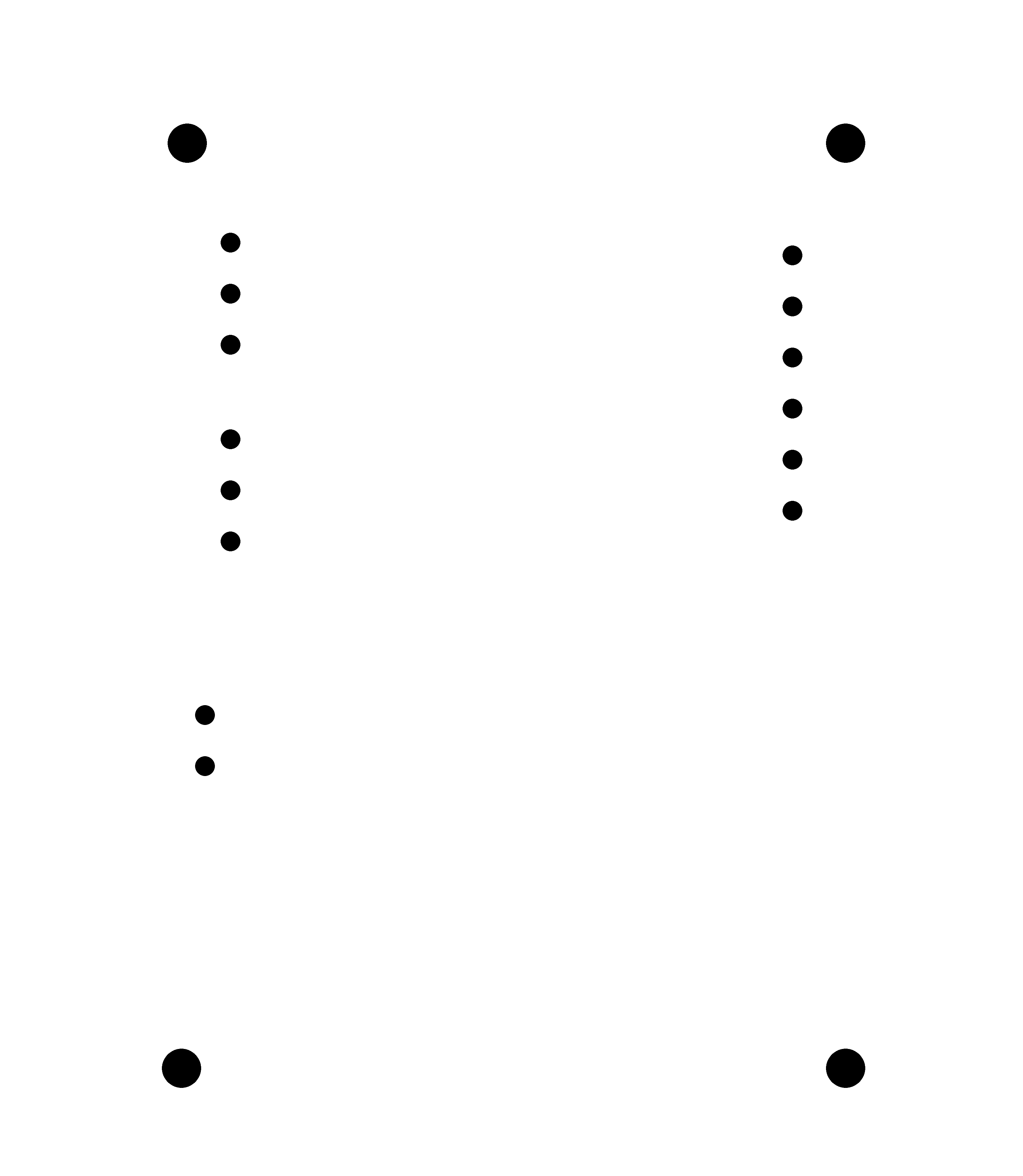
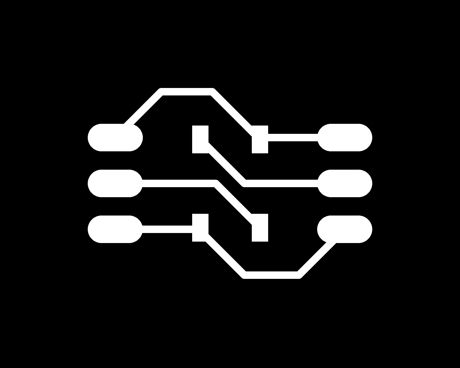
I designed the main board for final project which included a MCU, ESP32. I was planning to create the PCBs for the input device and the output one separately and connect them to the main via connector and cable.
Here was the board design for the main board.
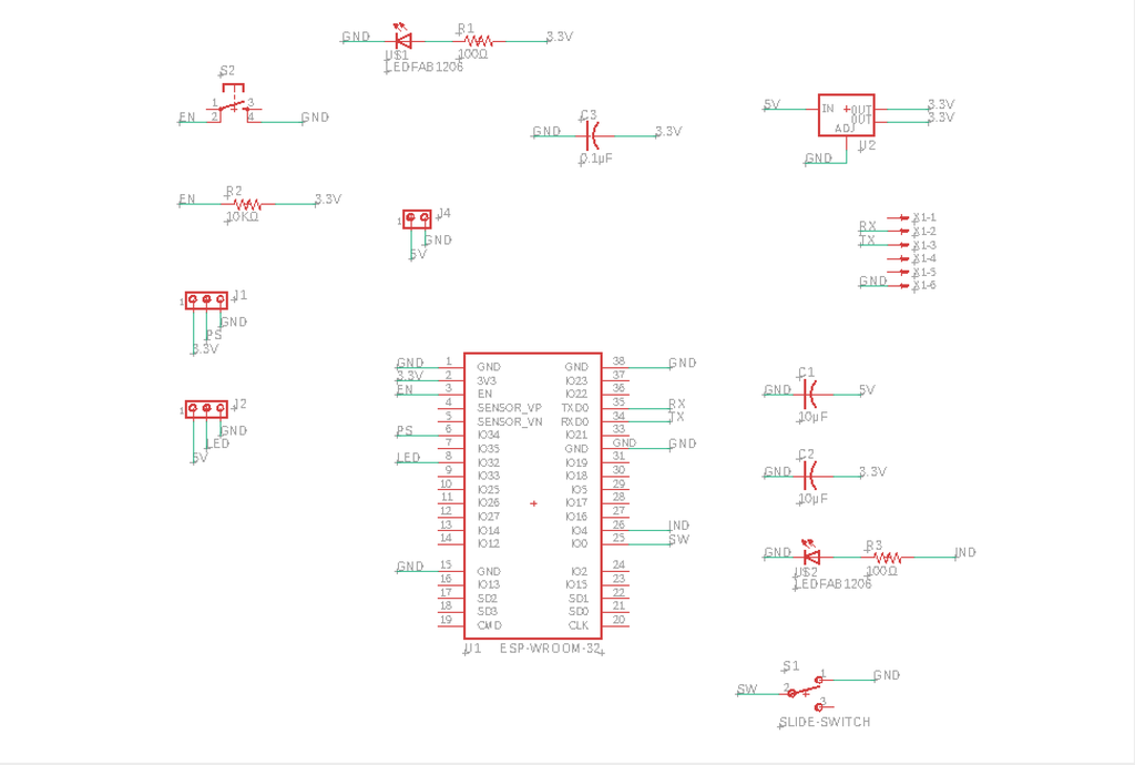
the pin 32 was used for the output device and the pin 34 was used for the input one.
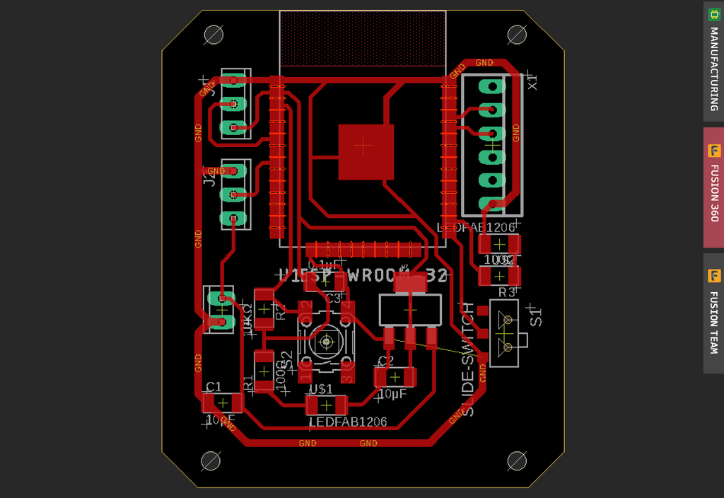
The footprints of ESP32 were too narrow to cut by CNC machine of our Lab. So I made their gaps slightly bigger by Photoshop after exporting as a png file.

the actual board
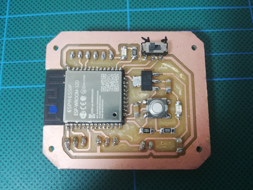
tested the board with the simple blink program
worked properly.
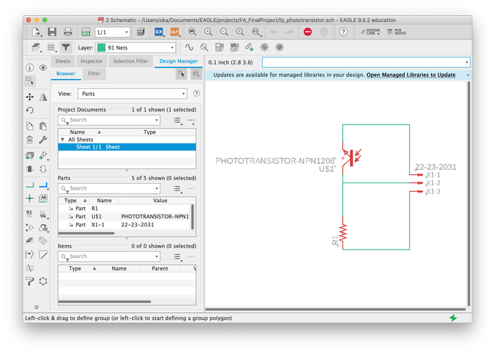
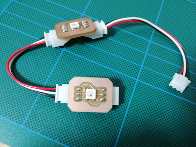
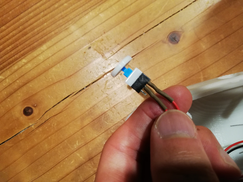
Input board
I made a small circuit board which included only the sensor and the connector to connect to the main board. I used the phototransistor called PT15-21C-TR8 as the sensor for the board.
the green mark on the left side of it meant the collector. It should be headed to the plus direction. the other side was the emitter.
There was no base even it was a transistor. if it detected the light, it works as the base function of the ordinary transistor.
Here was the board design
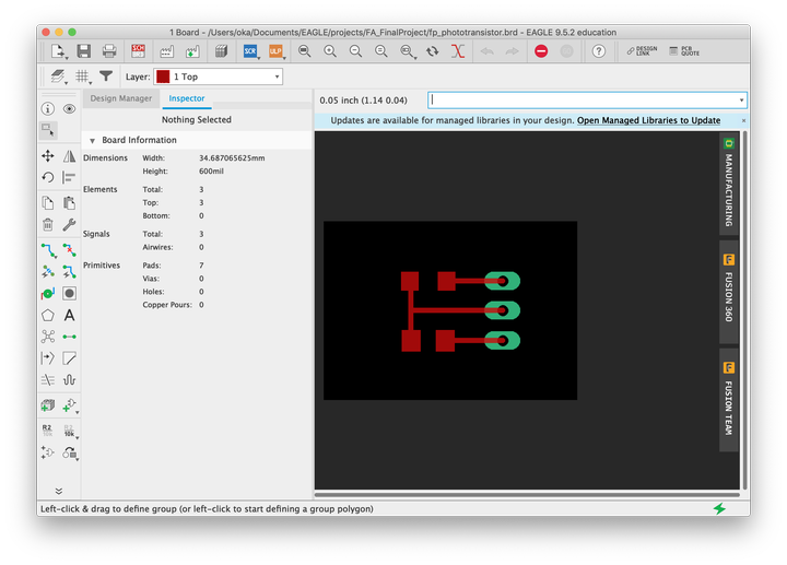
the actual board
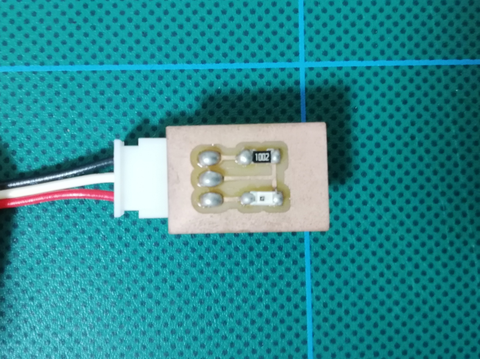
I tested the board to connect to the main.
The test programs was able to be downloaded from the link below.
test phototransistor(.ino)
It detected the light and the value were shown on serial monitor. when the light is detected, the value of the the quantity of light would be increasing. if there is no light the value would be 0.
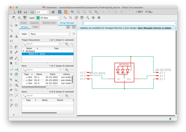
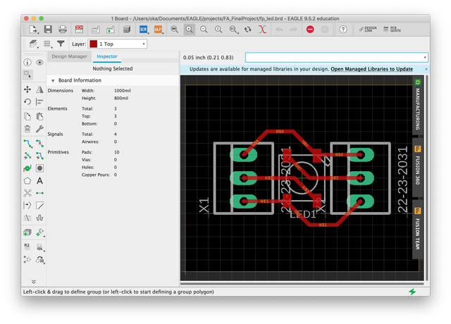
Output board
I created the board for the output device as well as the input one. I had decided to use Neopixel from an early stage because it was easy to control lighting condition. But, there was a problem to use it with ESP32 because the signal came from it has not enough voltage to be recognized by Neopixel properly. The voltage was needed around 4V but the signal only had 3.3V. Then, I found Neopixel named WS2812B-V5 which was newly released and it worked with signals of 3.3V according to its datasheet. So I chose it and tried make PCBs of Neopixel for my final project.
Here was a board design
the actual board
The test programs was able to be downloaded from the link below.
test neopixel(.ino)
The test succeeded. I used FastLED library and worked well.
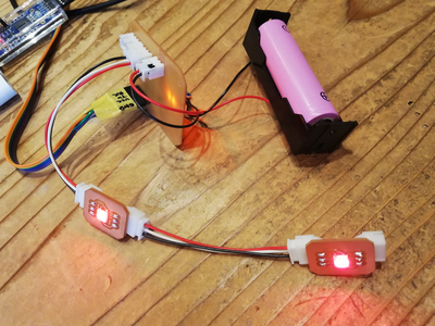
worked with the main board as well.
Painlessmesh
As I tried which was the library of Arduino on week 14, I made a program to control several LEDs in the mesh networking system. Mesh networking was the system which enable each node (ESP32, this time) to communicate each other without router. Each MCU could send a message to all the nodes. The rest of them could receive it and we could program to execute a something following the message.
I created a test program firstly. If the phototransistor on the main board had detected the darkness, the LEDs on it turned off and at the same time it sent a message to the ESP32 dev board next to it. Then the dev board got the message and turned its LEDs color from purple to red.
I revised the sample program of the library.
Here are important parts which I wrote by myself basically to achieve the function I needed.
The “void loop()” part
the normal program which was executed while MCU was working. I set the message(value) from this part using the function “sendMessage()”


The “void sendMessage()” part
Got the message(value) from the outcome of the loop part and set it for transmitting on mesh network to send it to another node.


The “void receivedCallback()” part
Received the message(value) from another node and then run the program based on it.
And the actual two program (one for transmitting and the other for receiving) are able to download here.
Program for transmitter (main board)(.ino)
Program for receiver (ESP32 dev board)(.ino)
worked as I expected.
So I tried to combine all the program which I needed for the final project.
BLE beacon
The lamp needed the function to detect human. At first, I thought that I would simply use PIR sensor which could detect human by infrared ray to achieve it. But I found that it only worked for the moving object in my research. I wanted the lamp to keep turning on while human staying around. I also tested doppler radar sensor but it wouldn’t work as I expected either.
Then I gave up the idea to detect all the human who approached the lamp. Instead of it, I decided to use the tag thing and the lamp detected the human who had it. For making it, I used the system of the beacon which was possible to recognize the position of the tag based on BLE. There was the library called “ESP32 BLE for Arduino” which enabled to load that system on ESP32.
Basically, there are two kinds of programs, one for detecting and the other for transmitting. The one detecting could scan the strength of the BLE transmitting. So I programed as if it was more the specific value, LED would turn on. And the one transmitting was programed as it kept on transmitting whatever BLE signal.
The detecting program could find plural devices and it can get their RSSI stood for Received Signal Strength Indication and it meant the strength of the BLE signal. It usually used for the indicator of the strength of the WiFi signal for smartphone. So I used the value and compared to the maximum value which was from the area I didn’t want the lamp to turn on. If the RSSI was more than the value, it meant the human who had BLE tag got into the area where the lamp should be lit up.
The test programs were as follows.
BLE beacon detecting(.ino)
BLE beacon tag(.ino)
It worked well. Actually, ESP32 reacted to all the beacon transmitter by my program but it wouldn’t be the problem for my project so I decided to use it directly to my final project.
Combined Program
Lastly, I tried to combine the programs which I had tested on an individual basis.
But there was the problem caused by the data amount of the program exceeded the capacity of ESP32’s storage. Fortunately, someone who confronted the same problem had already documented the solution to it. It based on freeing the part of memory used for OTA(Over the Air) function. The OTA was unique to Arduino and it worked for updating its program automatically via the internet. If I reduced the part for OTA, I could use secure the area for my program.
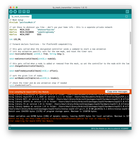
I tried the same procedure following the article(Japanese source).
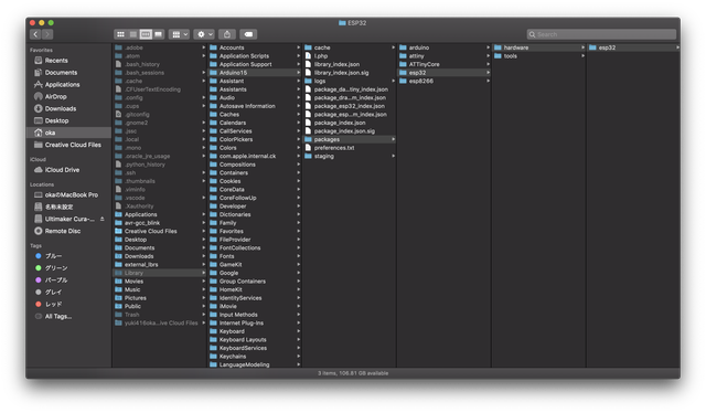
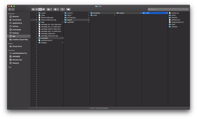
According to the instruction, I needed to rewrite the file called “default.csv.”. The file existed in the place below.
/HOME/Library/Arduino15/packages/esp32/hardware/esp32/1.0.0-rc4/tools/partitions/default.csv
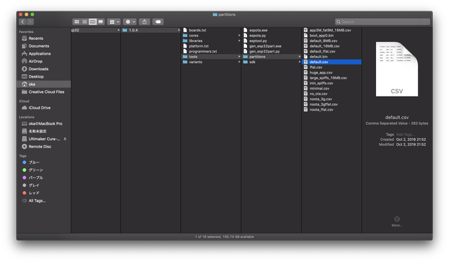
If you couldn’t find the Library folder, use short cut to show hidden folder ( command + shift + . ).
In the original file, there were two sections named “app0” and “app1” for securing the area for programing as the image below.
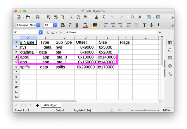
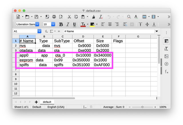
I needed to combine them and make the one which secured bigger area. So I edited it as below.
And, I needed to edit boards.txt as well. The file was in
/HOME/Library/Arduino15/packages/esp32/hardware/esp32/1.0.0-rc4/boards.txt
I edited the file as I show below.
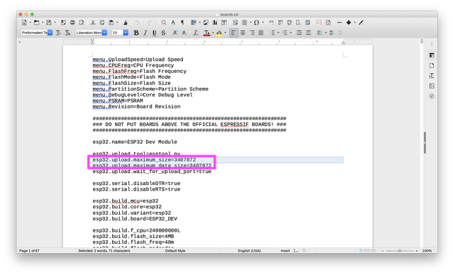
esp32.upload.maximum_size=1310720<br>
esp32.upload.maximum_data_size=1310720<br>
↓
esp32.upload.maximum_size=3407872<br>
esp32.upload.maximum_data_size=3407872<br>
The capacity for program was expanded about threefold. Then I could load the final program. I unified all the tested programs into one. I put it below.
3D print
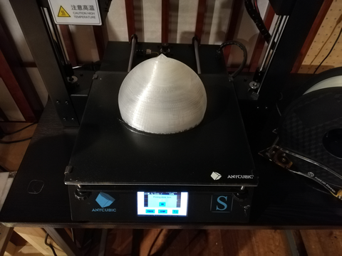
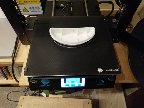
I printed the 3D model I designed on Fusion360 previously. I used the printer called “anycubic i3 MEGA“ and the PLA filament sold by Pxmalion. I used two colors of filament. The one was transparent for the top part because the light was needed to pass through the body. The other was white for the bottom part.
Timelapse while printing top part
Top part
Bottom part
Button
Button was designed to be able to attach to a alternate switch.
Clip part for fixing input and output board.
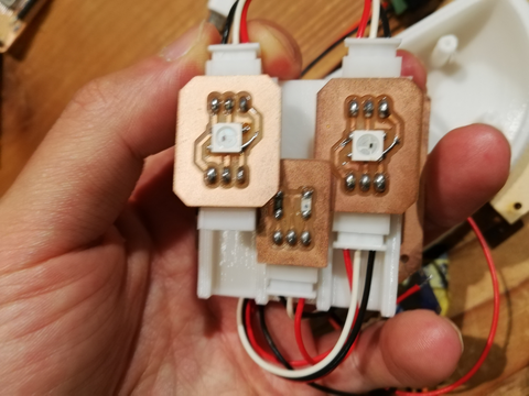
First try was failure. the boards interfered each other.
Modified version. Had two holes to tighten the screws on the mainboard under the clip.
Second version worked perfectly. The clip was really effective to organize the contents in the lamp.
Laser cut
I designed the charging place for the lamp. Using the laser cutter, I carve the ditch to embed the coil and PCB for the wireless charging system. I used the off-the-shelf kit for that this time because I felt hard to create it by myself when I tried it for the weekly assignment on week16. The charging system didn’t need program to run so I just connect it to 12V 2.0A AC adapter. it with The charging was conducted properly even the coil was covered by the MDF 3mm thick.
Outcome
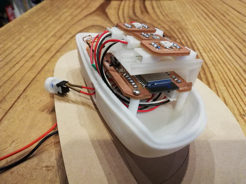
I could prepare all the parts so assembled them.
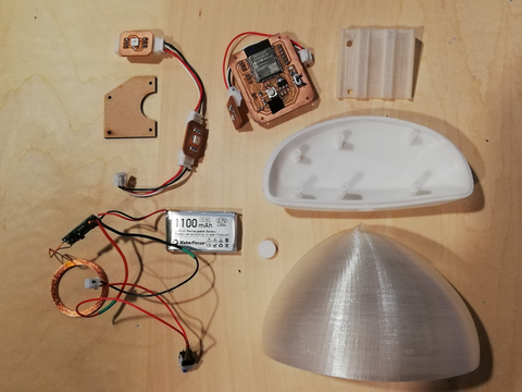
All the parts I prepared.
video of assembling.
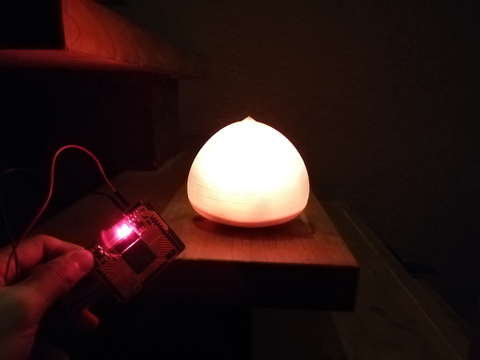
It reacted to beacon tag
A lamp worked individually well. But unfortunately, networking didn’t worked. So I changed program as a lamp worked without networking.
It couldn’t be controlled precisely by networking as the initial idea. But it worked as the integrated product of input device (phototransistor and BLE beacon) and output device (neopixel) which met the requirement.
I have finished the project with the following points
Worked / achievement
- 3D printed body was output better than I expected
- phototransistor(input) and Neopixel(output) working properly with ESP32
- using wireless power supplying system(off-the-shelf kit) and lasercutting for its packaging
- using BLE beacon as a proximity sensor
These points seemed to meet the requirement for the final project.
On the other hand, I couldn’t complete the plan I made firstly and +α as follows.
Didn’t work / unreached goals
- each devices should communicate each other by mesh networking (painlessMesh) but it couldn’t.
- didn’t prepare BLE tag as a proper product version.
- tried to control the color of LED by BLE beacon tag but couldn’t read the data properly
- making mold by 3D printer but the material liquid leaked from the gap between each layers and body and mold made adhesion
- attaching a chestnut-burr like decoration to the base board
I gave up with these points because of time constrains. It could be the goals for second cycle if I continue to create the product.
And I am thinking that the networking system I used this time could be the outdoor sensing system to collect data from anywhere in my hometown. So I want to test it as a next project in the future.
Links to Files and Code
The main board for final project
Eagle sch (.sch)
Eagle brd (.brd)
Traces(.png)
Outline(.png)
Holes(.png)
Traces cutting data (.rml)
Outline cutting data (.rml)
Holes cutting data (.rml)
The board for phototransistor(the sub board for the input device)
Eagle sch (.sch)
Eagle brd (.brd)
Traces(.png)
Outline(.png)
Holes(.png)
Traces cutting data (.rml)
Outline cutting data (.rml)
Holes cutting data (.rml)
The board for Neopixel(the sub board for the output device)
Eagle sch (.sch)
Eagle brd (.brd)
Traces(.png)
Outline(.png)
Holes(.png)
Traces cutting data (.rml)
Outline cutting data (.rml)
Holes cutting data (.rml)
The data related to 3D model
3d model (.f3d file)
body top data (.stl file)
body bottom data (.stl file)
clip part data (.stl file)
button part data (.stl file)
base board top data (.pdf file)
base board bottom data (.pdf file)
Final program
fp_fin(.ino)