Group Assignment
For this week’s assignment we need to review the safety sheets for the molding and casting materials we’ll be using. I’ll work with standard RTV (Room temperature vulcanizing) silicone as mold material and gypsum, and polyurethane resin as casting materials.
Molding material: Silicone
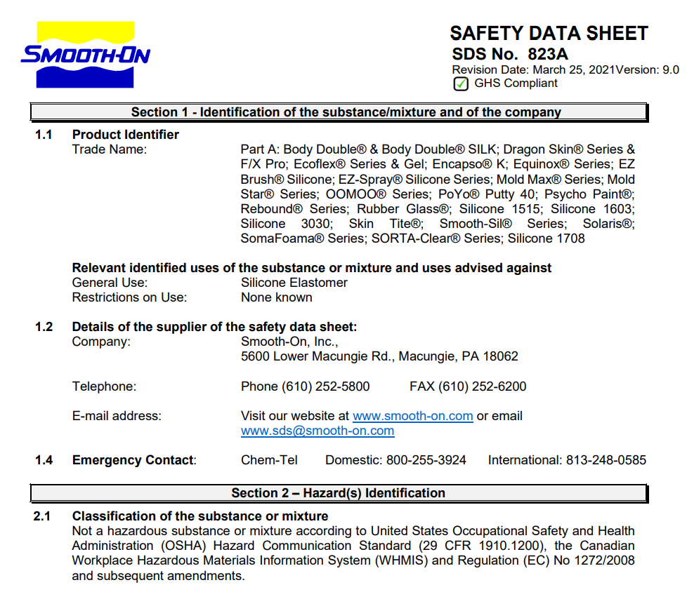
The silicone used is very similar to OOMMOO from Smooth-on ****. This is a very easy-to-use silicone, and according to its Safety Sheet very safe to use too. The safety measures are to use eye protection and gloves, as it is not considered a hazardous substance.
Casting material: Polyurethane Resin
As casting material I’ll be using Polyurethane resin similar to Smooth-Cast 305 also from Smooth-on, this is a two component resin called liquid plastics are ultra-low viscosity casting resins that yield castings that are bright white and virtually bubble free.
Because this is a two part material its safety sheet is also divided into part A and Part B, Curiously enough part A is considered hazardous and part B is not.
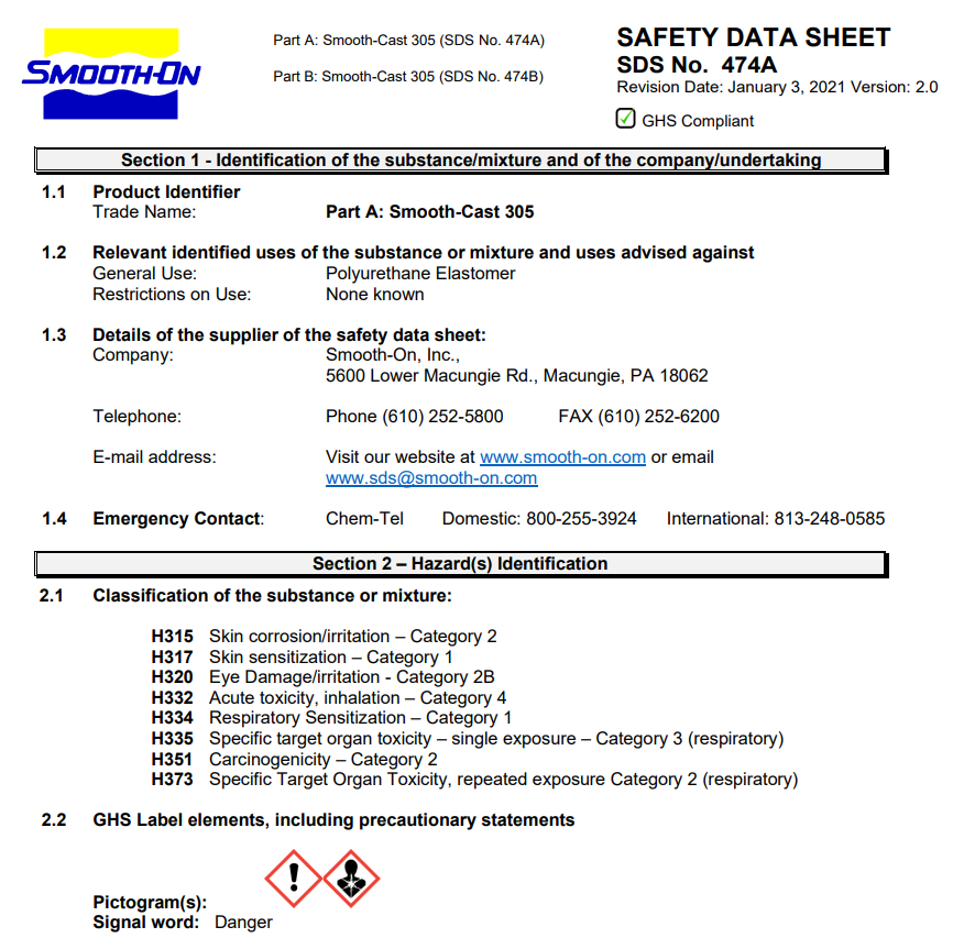
Some of the dangers associated with Part A include Skin irritation, Eye irritation, and respiratory sensitization so I’ll be handling this material with protective gear and in a well-ventilated area.
Casting material: Gypsum
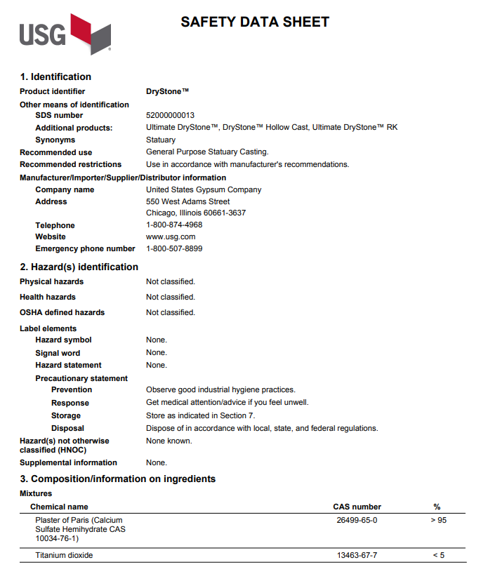
As another casting material I’ll be using gypsum, this is similar to USG Ultimate Drystone, that according to the website is a unique product that requires no oven drying that offers excellent duplication of fine detail, high compressive strength, and a high density that provides a quality feel. Ideal for solid cast pieces formulated to increase chip resistance and is an excellent alternative to polyester resin.
According to the Safety sheet, this is also not considered a hazardous substance, so the same precautions as using eye protection and gloves are needed.
Molding and casting test
For the silicone test, I poured a 50g amount into a plastic cup, after 4 hours the silicone was already dry. This kind of silicone is not very stretchy, some bubbles rose to the surface may be because of poor mixing but this does not appear to affect the mold.
For the polyurethane resin, I used a silicone mold that I had around I mixed carefully the two parts that made a golden liquid, after pouring the mix into the mold the reaction started almost immediately, it took around 15 minutes for the part to be solid but still a little soft. around half an hour later the part was hard. it also formed some bubbles on the surface, maybe because it was moisture on the mold, this type of resin is very sensitive to moisture.
for the gypsum test I also used a silicone mold, this is kind of a small tray, and the plaster I'm using has a subtle blue color. The mixing ratio is 10% to 15% water to plaster. I used a drill with a mixer attachment. The mix dried in about 20 minutes but was still warm to the touch when demolding.
A final shot in the tests
Individual Assignment
The goal for this week is to design, 3d mill, mold, and cast an object. I wanted to challenge my mold-making abilities to make a slightly complex geometry.
The inspiration
I’ve always been fascinated by the shape of the coastal barrier blocks, and how these giant concrete shapes come together in a chaotic yet pleasant structure.
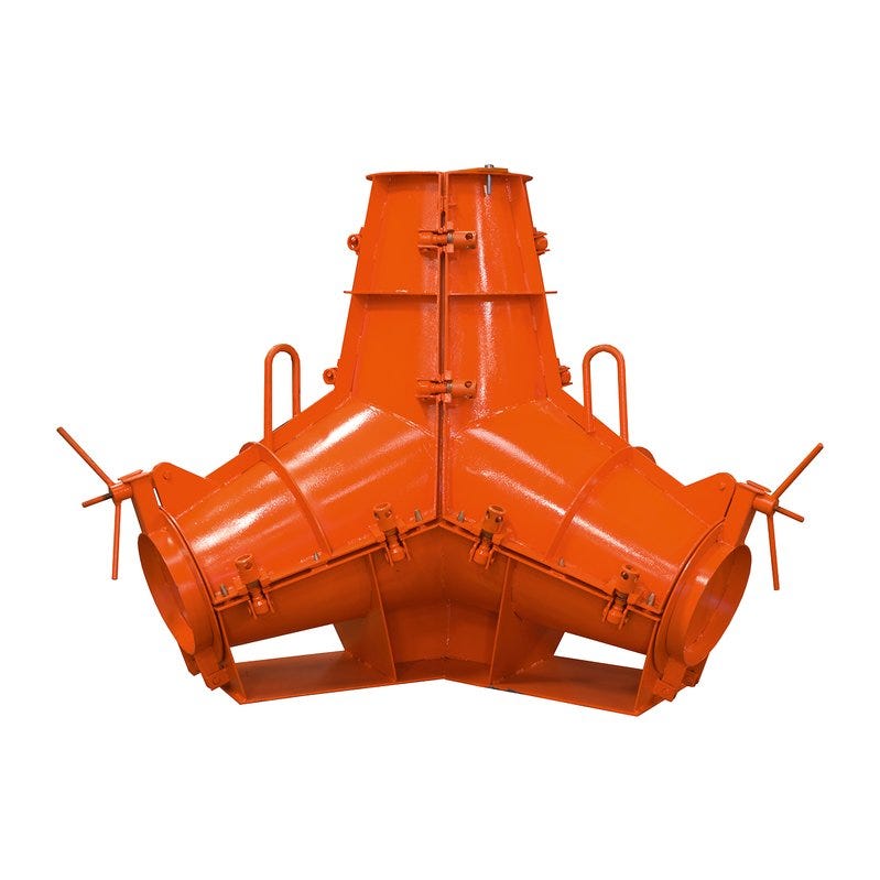
The shape I choose is called a Tetrapod (4 legs), designed in 1950 by French engineers Pierre Danel and Paul Anglès d’Auriac. I choose this design for its rounded shape that looks pleasing to hold and will look very cool as a paperweight.

These are normally cast in steel molds of several parts. This particular tetrapod mold is from Betonblock, and its prices are up to 9000 euros depending on the size.
Here’s a cool video if you want to know more about the tetrapod life
The Design
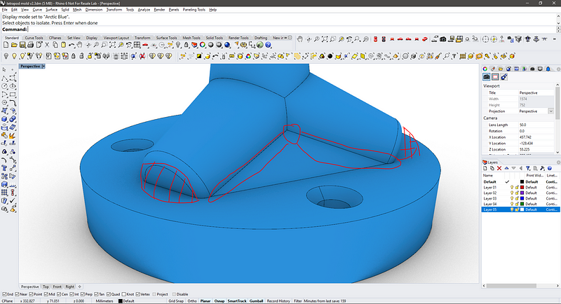
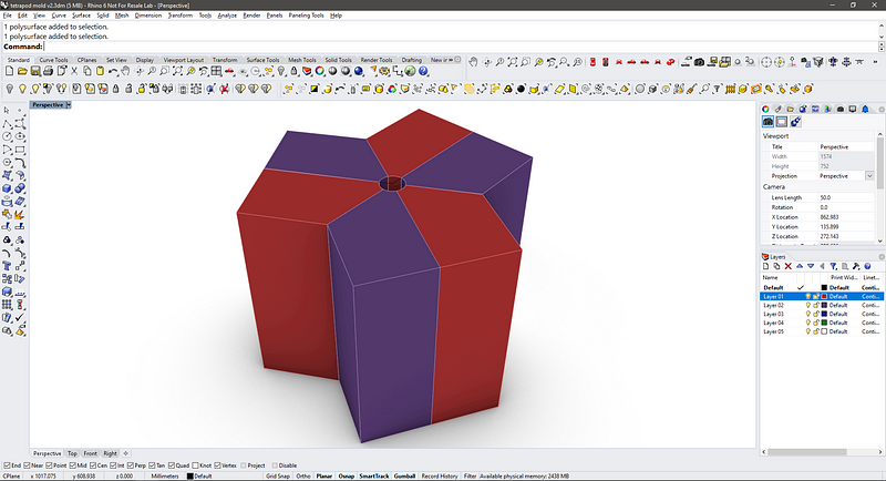
I begin working on the model on Rhino 6, the modeling’s quite straightforward, I started with a truncated cone, (vertical) made it a block, and copy this shape 3 times to make the legs, each separated by 120° degrees. Notice that the tetrapod does not lay flat.
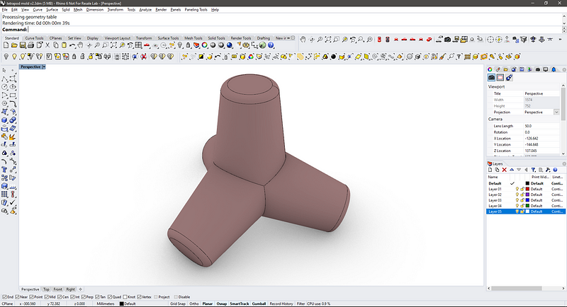
I wanted to make the molds as simple as possible, keeping the number of molds to a minimum, this would not be easy as the tetrapod does not have a single edge of symmetry.
I tried to cut the shape in two, following the edge of symmetry of the legs to avoid undercuts in the milling. This will divide the shape between the top and the base, so two molds!
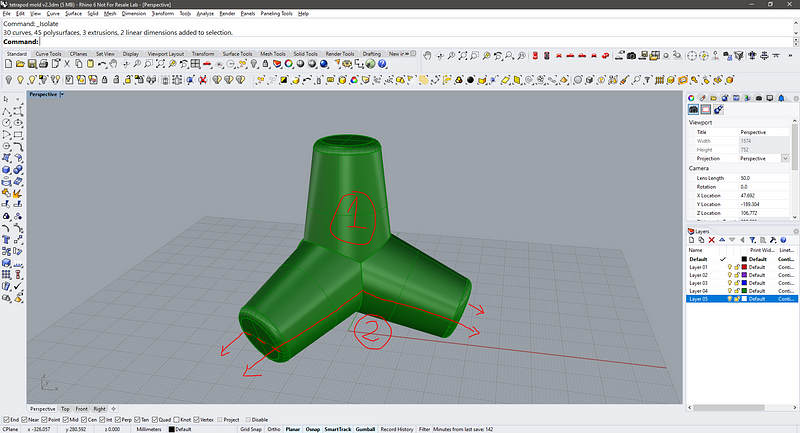
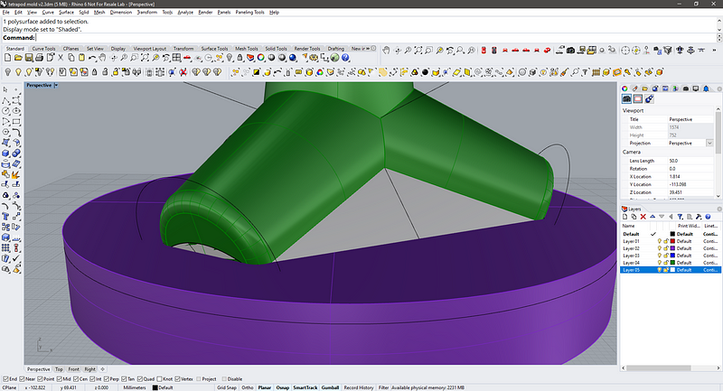
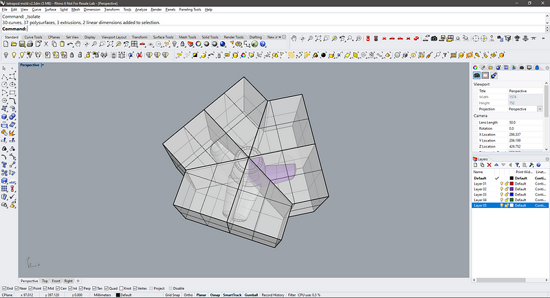
To make this complex cut I modeled a 3 sided pyramid and cut the base corners according to the normal face of the legs. Here’s the grey pyramid partially inserted in the tetrapod, and a purple base that matches the height of the center of the legs.
These 3 solids would combine to form the milling positive for the top.
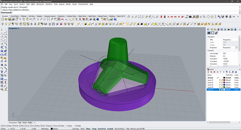
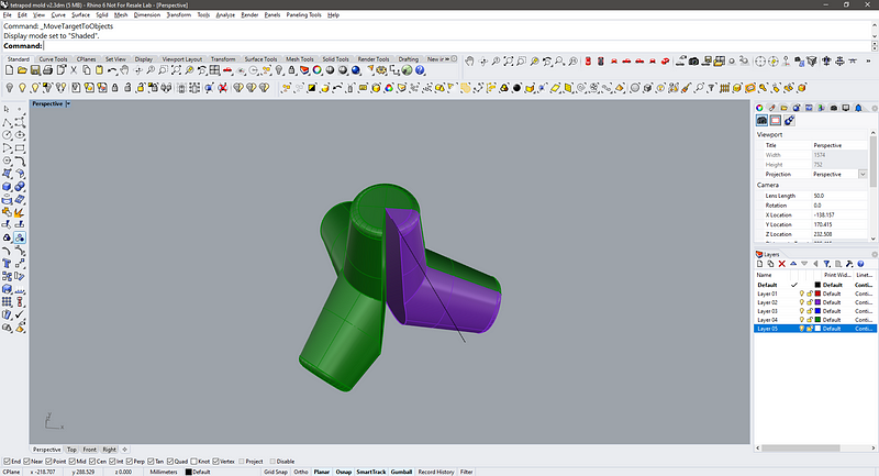
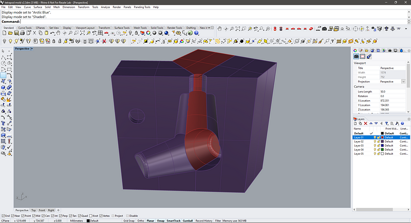
Using the pyramid and the base as a reference I cut another solid to form the bottom part of the tetrapod. This is simply made by modeling a cylinder for the base of the purple base to the top of the tetrapod (and a little more).
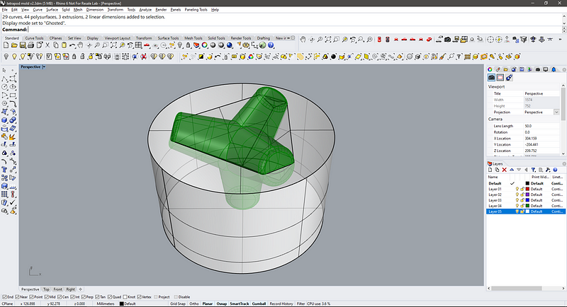
This new cylinder it’s cut with the pyramid and turned upside down, here you can see the tetrapod inside the freshly cut cylinder. These two will fuse to make the milling positive for the bottom.
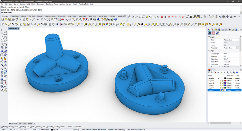
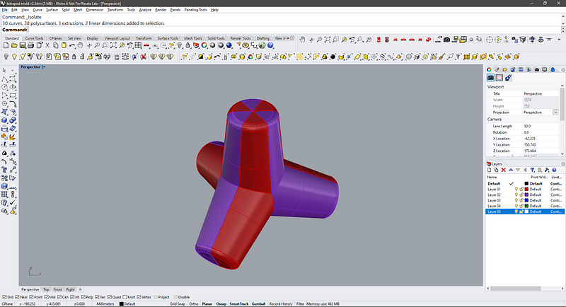
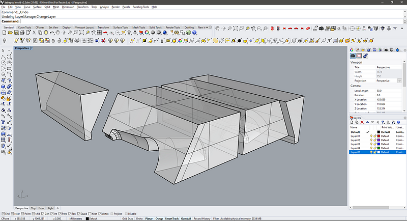
These are the two final milling shapes for the top and bottom.
I know, they look really good, but something’s not right… As I was modeling it I noticed that it was especially tricky to make the cut aligned to the normal of the truncated cones, because getting it too high or low, will generate undercut geometry that could not be milled. Let’s look closer:
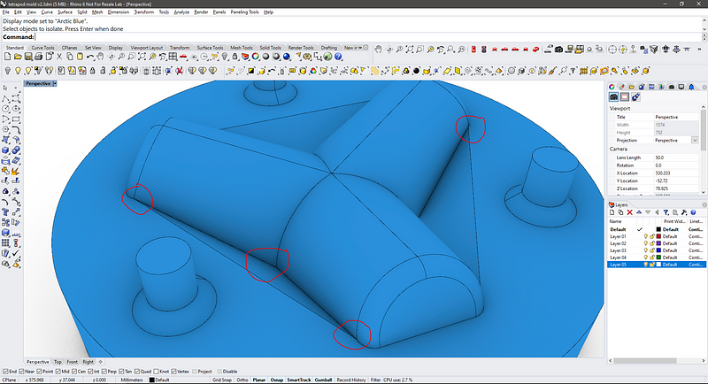
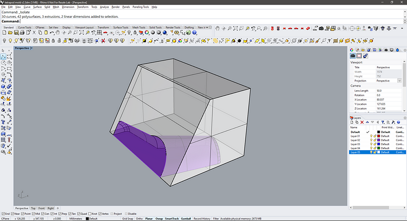
These are hard to reach spots on the model, the tight intersections in the geometry would make it almost impossible to mill it because of the diameter of the milling bit, this would surely work fine on a 5 axis CNC, but not on the Modela or Shopbot.
The other half face the same issues and some sections of undercutting geometry on the legs that I figured I could cut out with a hot knife through the wax after the milling, but maybe it’s cheating.
Another issue is that the top part it’s higher, and it might be higher than the wax block itself.
The shape could be milled, and it will make a tetrapod (sort of), but the two sides will not match perfectly. Looks like this was not a good approach after all… back to the drawing board!
The Design (again)
It looks like the only way of making the tetrapod right, (this means working with a 3 axis CNC milling on a positive shape) is to follow the symmetry axes. This is clear on how these are cast with mirroring steel panels.
This approach begins with cutting the tetrapod into 6 parts, copied around the rotation center.
In purple its the extracted piece for the mold (1/6 of the tetrapod, 60°) this needs to be mirrored to make the other side (red piece), these two pieces joined form 1/3 of the tetrapod and repeated, so two mirror molds!
The crucial part of the design is to not have undercut geometry, so this new piece needs to be correctly oriented on its wider flat side. This is the simulation of the casting rubber around the piece, notice that the angled flat side of the purple piece needs to stay clear to join the other molds, but as it is angled, it is forming an undercut!
The six molds combined should look somehow like this:
I figured to avoid this undercut that I could mill a straight wall, add a piece of plexiglass to form the angle, and then pour the casting rubber. So I need some kind of edges to hold this new piece in place.
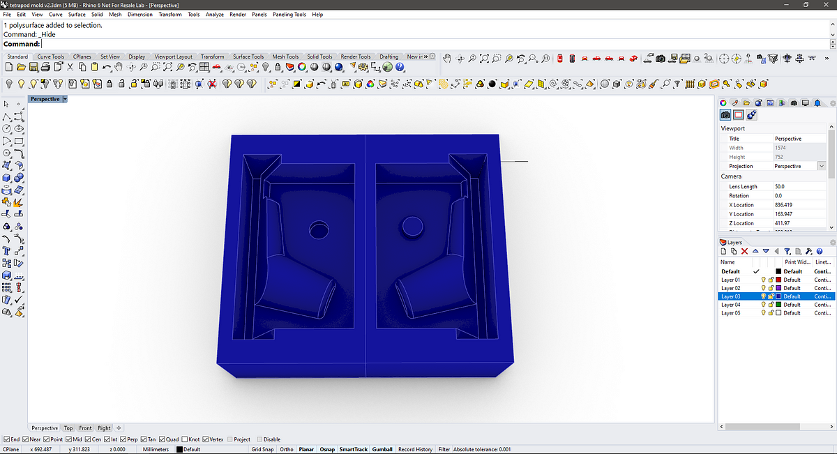
These are the two sets of molds (negatives, so this would be the casting rubber) to be subtracted to the wax block. The second solid that is wedge-shaped will form the edges for the acrylic, so it protrudes 5mm of each side. I also added a cylinder to the top to make a hole to pour the final cast.
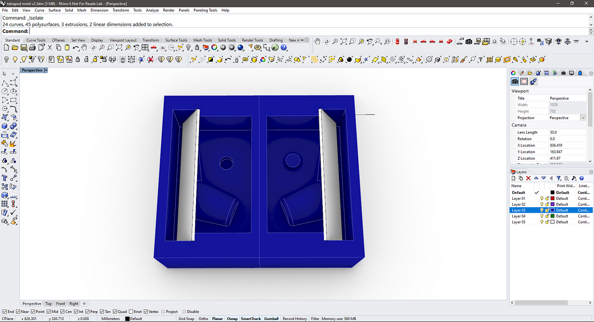
After making a boolean difference to the wax block (blue) with the above geometry this is the result. I added a register pin to help get the molds in place when casting.
And this with the acrylic plates in place and ready to pour the rubber to form the negatives, three for each side!
The combination of negatives or rubber molds should look like this:
Inside of the mold (half):
Notes:
The molds only fit together in pairs due to the registration point added, but it would need a rubber band (or maybe a custom-made laser-cut boundary) to hold the six pieces firmly.
As the acrylic plates need to be removed between casts this could damage the wax mold.
Simulating Machining: Generating toolpaths with Fusion 360
With the .stl file exported, I began to work on Fusion 360. This is the first time I’ll be trying the CAM environment of Fusion, and also the first time I’ll be working on milling paths since the computer-controlled machining week assignment was postponed due to the outbreak. 😥
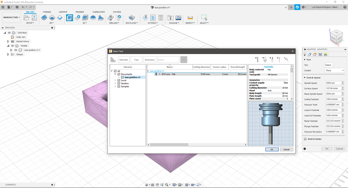
The first step is to change the work environment to manufacture, then select the kind of work we’ll be doing, in this case, adaptive clearing. Next, we create a tool for the milling, as I didn’t have this information I selected the default options. The tool is a 10mm diameter flat end mill.
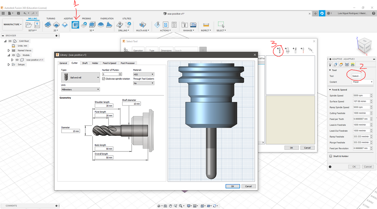
The tool is a 10mm diameter flat end mill.
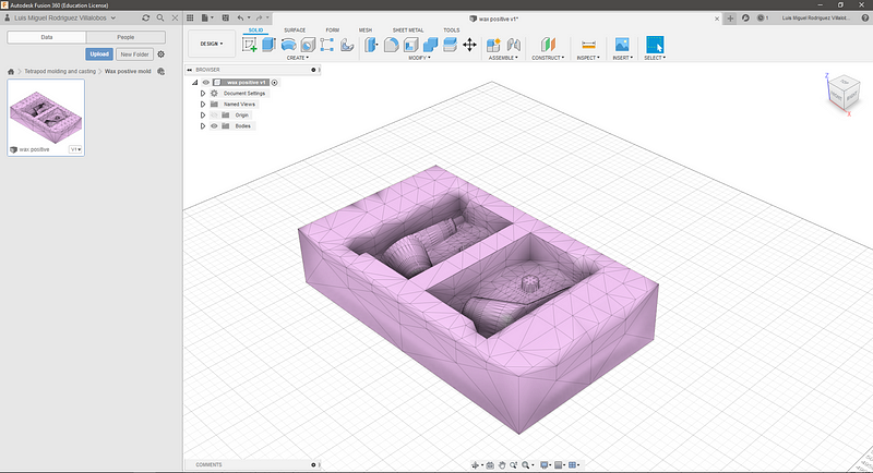
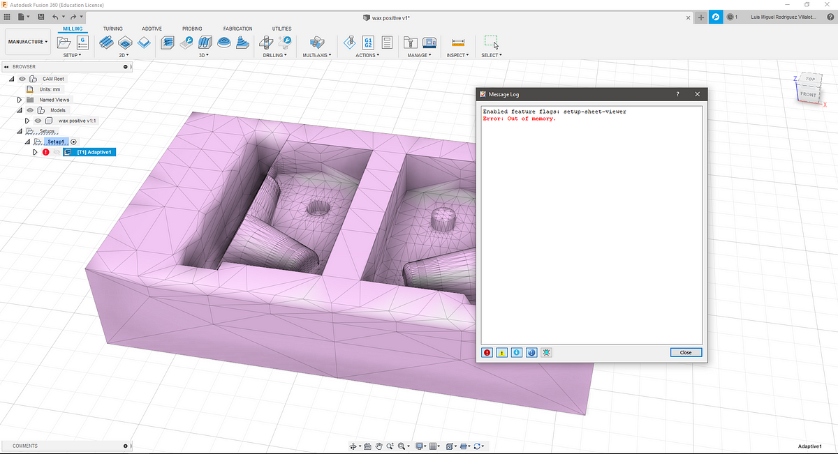
Unfortunately, the path generation was taking too much time, and finally, it ran out of memory, I guess this is because I was working with the .stl file I exported from Rhino, and somehow I needed to convert it to a Fusion 360 solid.
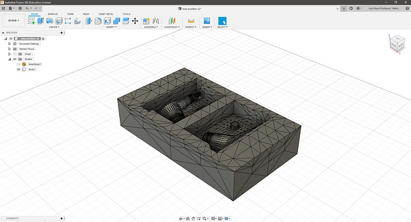
I used this tutorial as guide to convert the mesh to a solid:
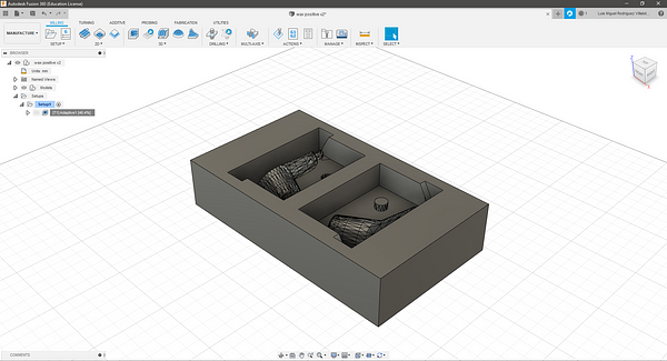
After a bit of geometry cleaning (the video also shows how) the solid looks like this, it’s was not possible to clean the curved surfaces.
Simulating Machining: Generating toolpaths with MODS CE
Sadly the Modela at Fablab it's not working as it should so I’ll be working with MODS to see the milling pattern. In the new MODS, there's no program for 2.5D milling with the old Modela MDX-20.
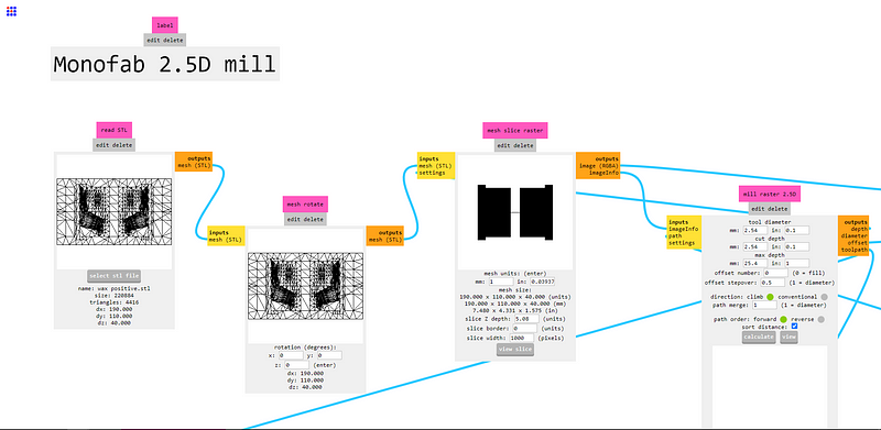
After loading the .stl file and hit calculate, the program starts calculating but does nothing, looks like MODS might be broken too! Upon closer inspection, looks like there is a lot of nodes that weren't there before… maybe ill check on MODS later.
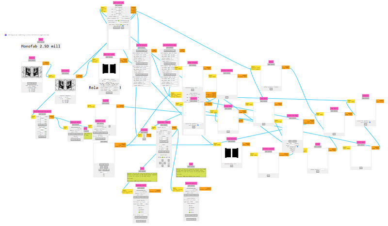
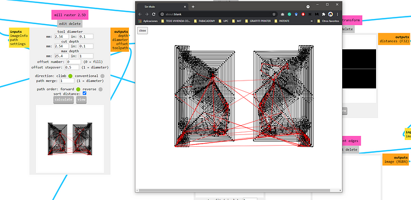
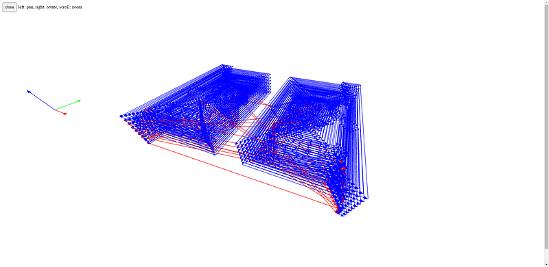
After a couple of minutes, MODS is working like it used to, so I reloaded the .stl file and hit calculate, this time it took like a minute to show the complete milling paths.
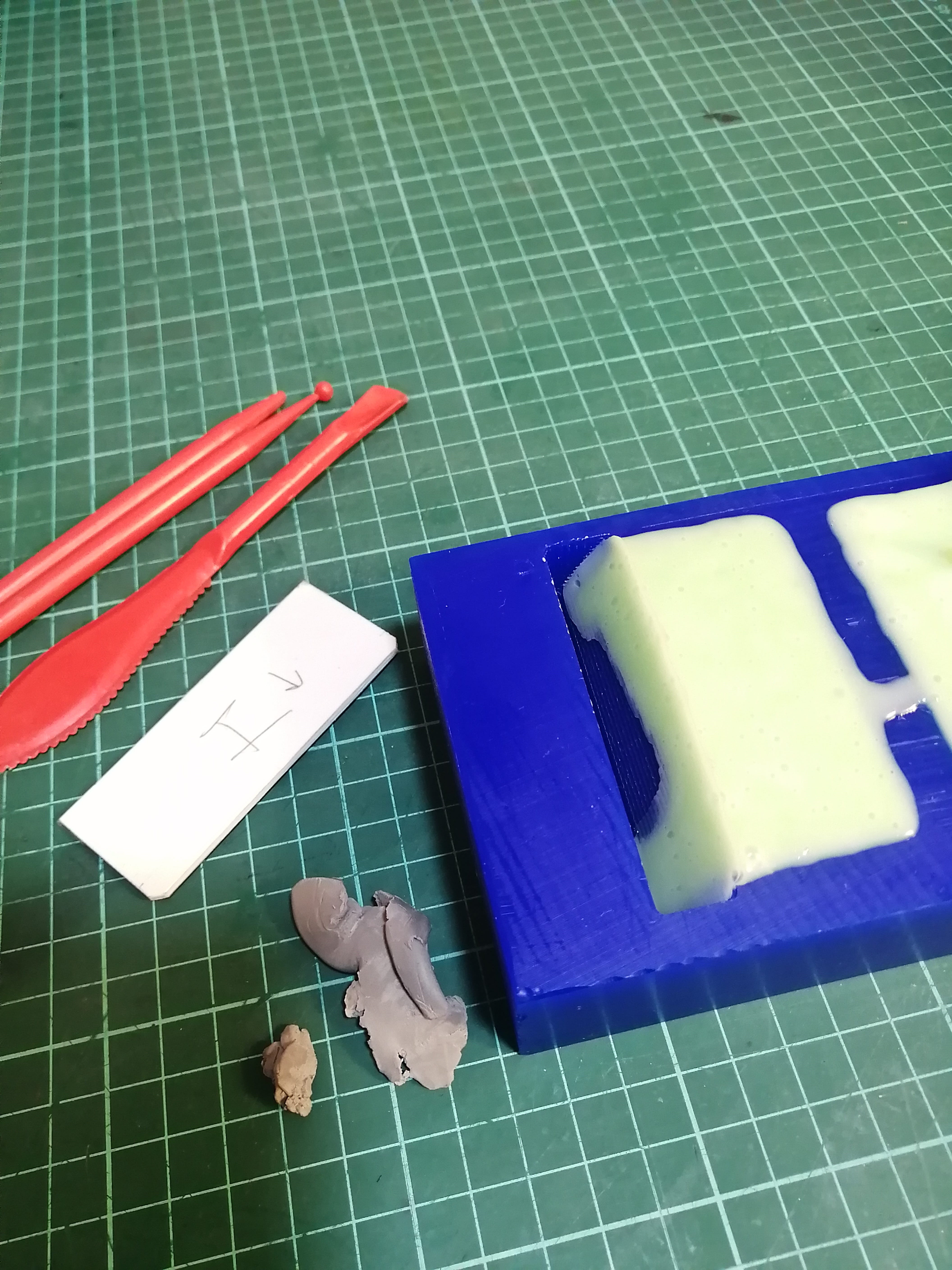
Molding and Casting!
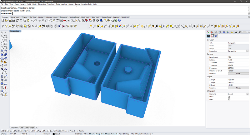
I could not wait for the Modela to work so I took a different approach to molding and casting (I'm sorry Neil!), I'll be 3D printing the molds to see if my idea works in practice. The first step is to simplify the 3D wax positive into a quicker .stl for 3D printing but with the same logic as I would use the CNC. So basically now the molds are in two parts, with thinner walls.
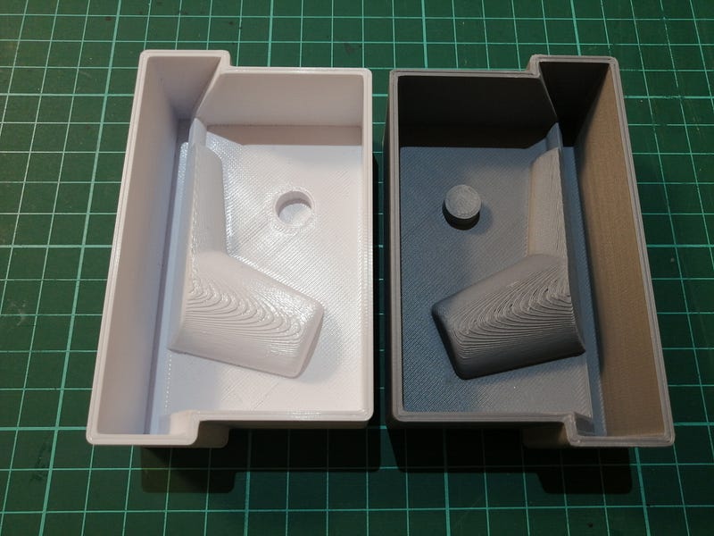
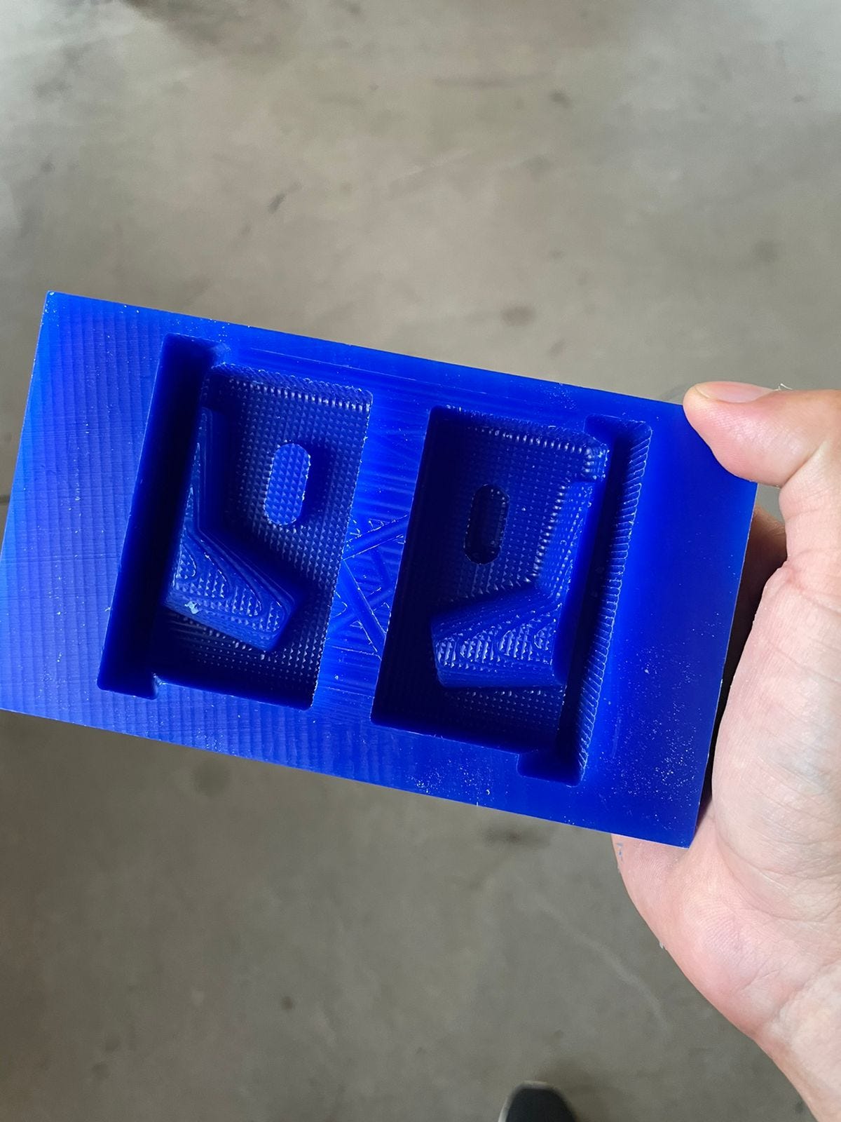
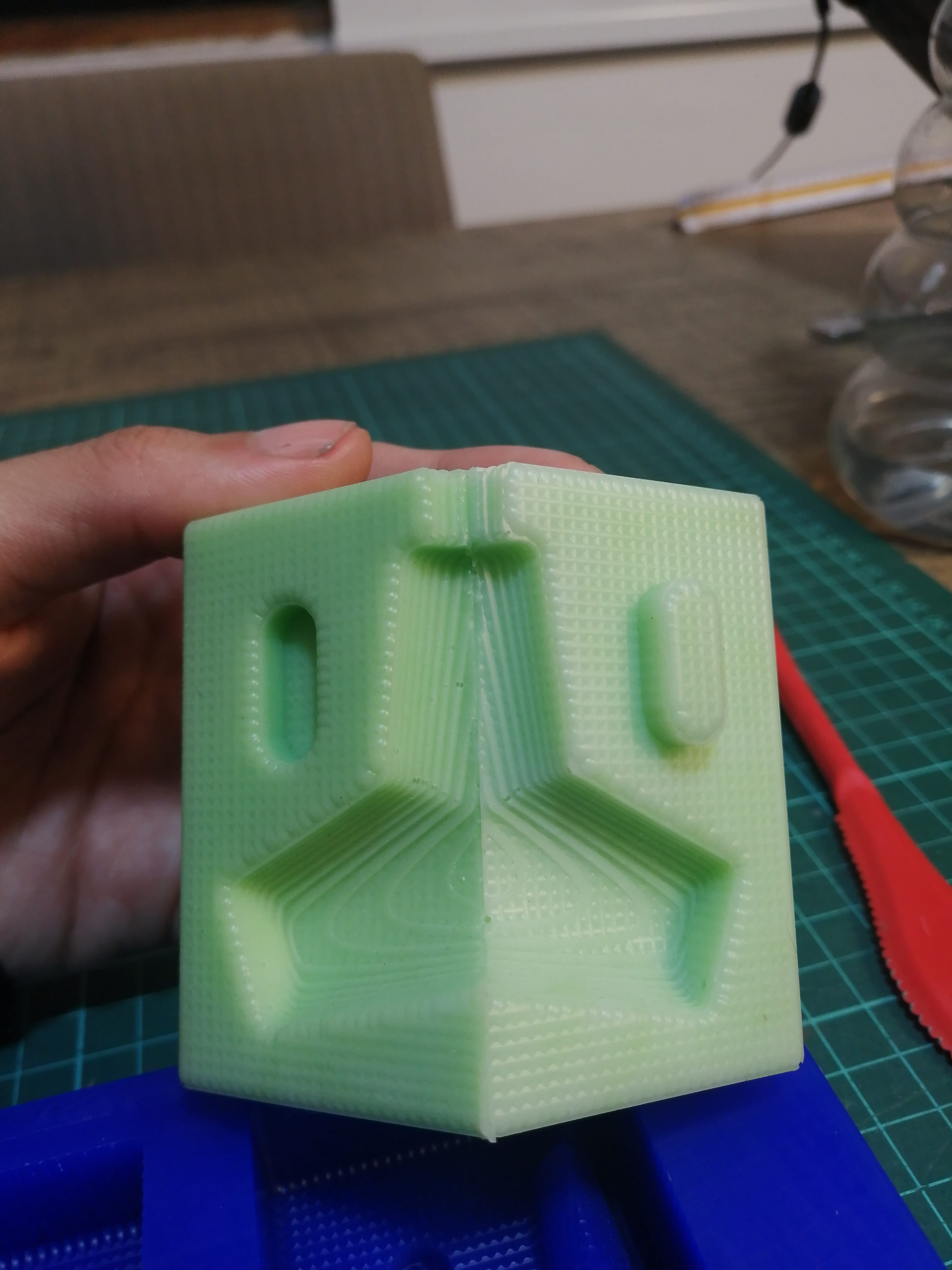
It took around two hours each to get it printed, I've used 0.28 layer height to make them faster and I thought this will add a nice texture to the casted part. These are the finished 3D printed molds, one with white PLA and one with a new filament called Polyterra from Polymaker, an eco-friendly filament.
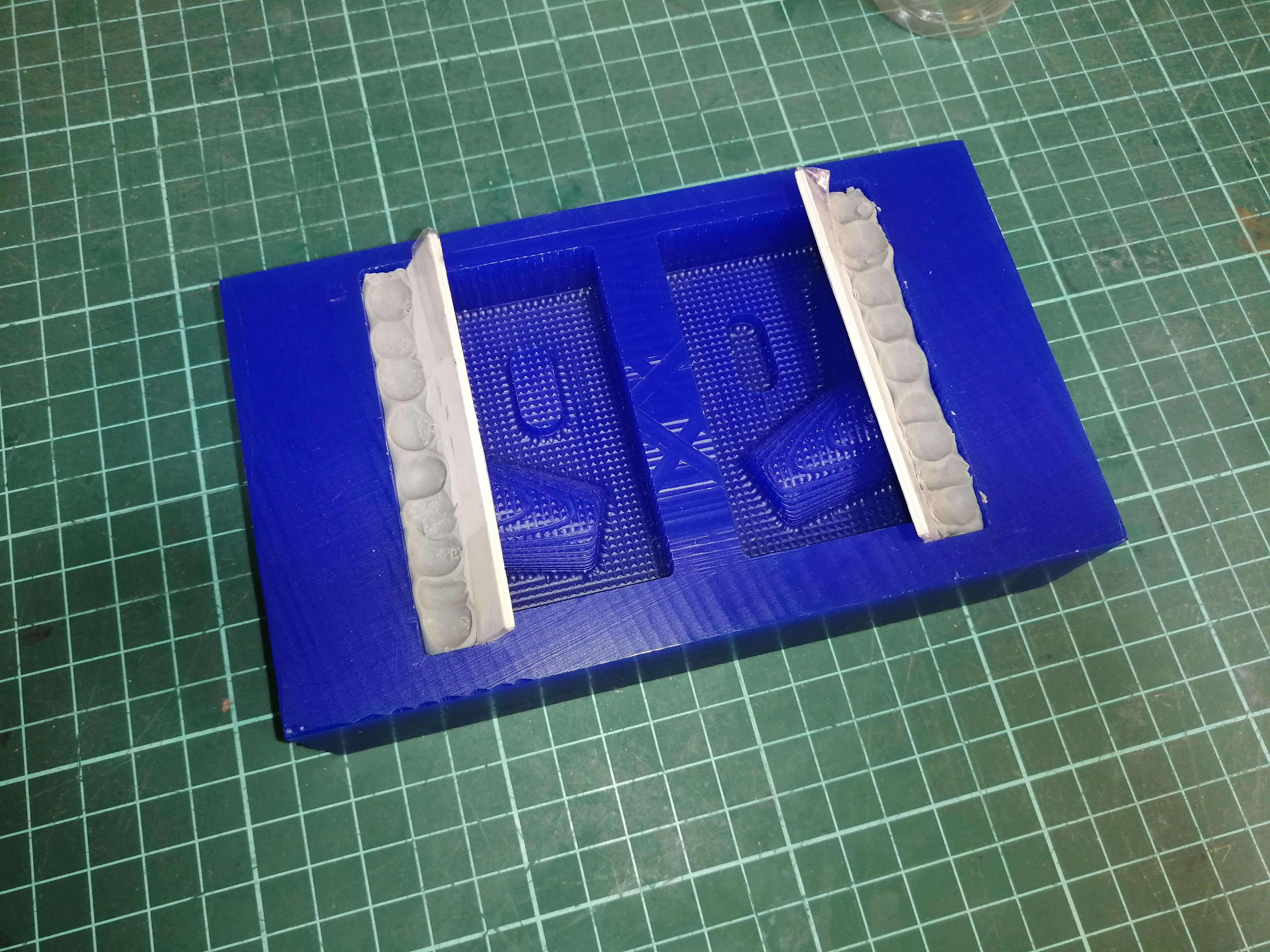
The molds will be complete with a cardboard piece to get that angled face that it's impossible to CNC mill. The cardboard is wrapped on plastic tape not to stick to the silicone.
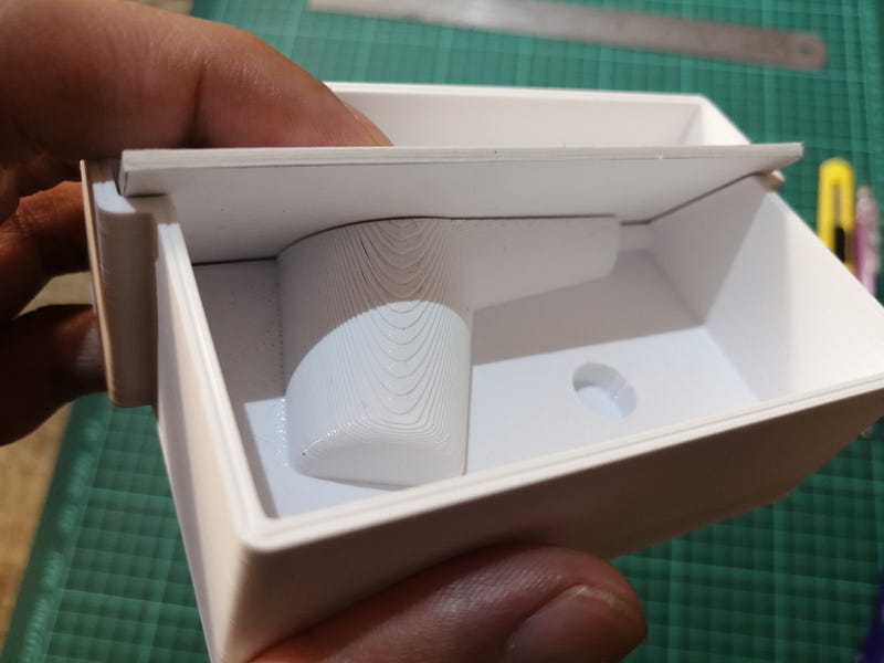
To keep the cardboard in place I added some plasticine between the cardboard and the mold and press it to make a tight fit.
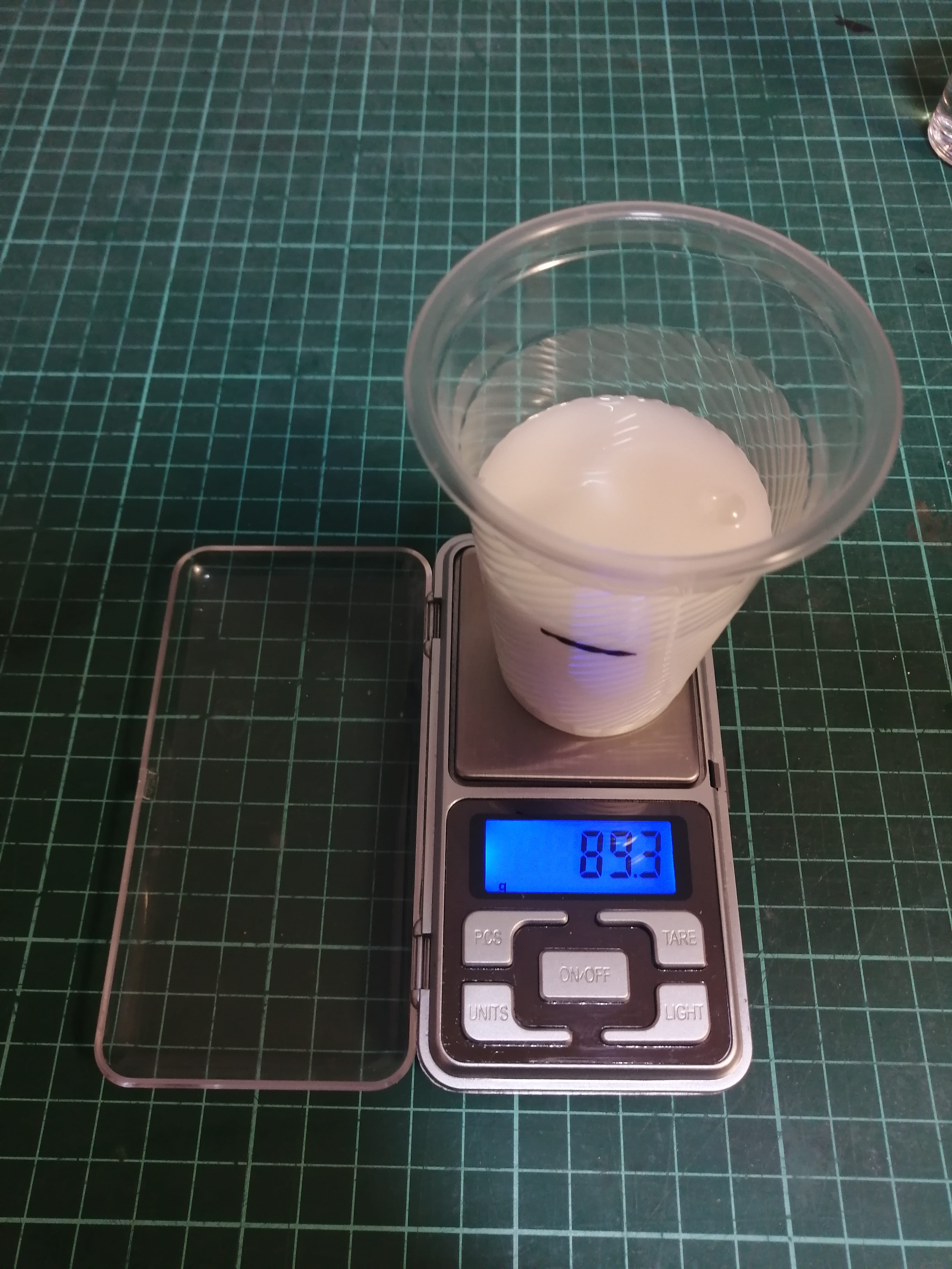
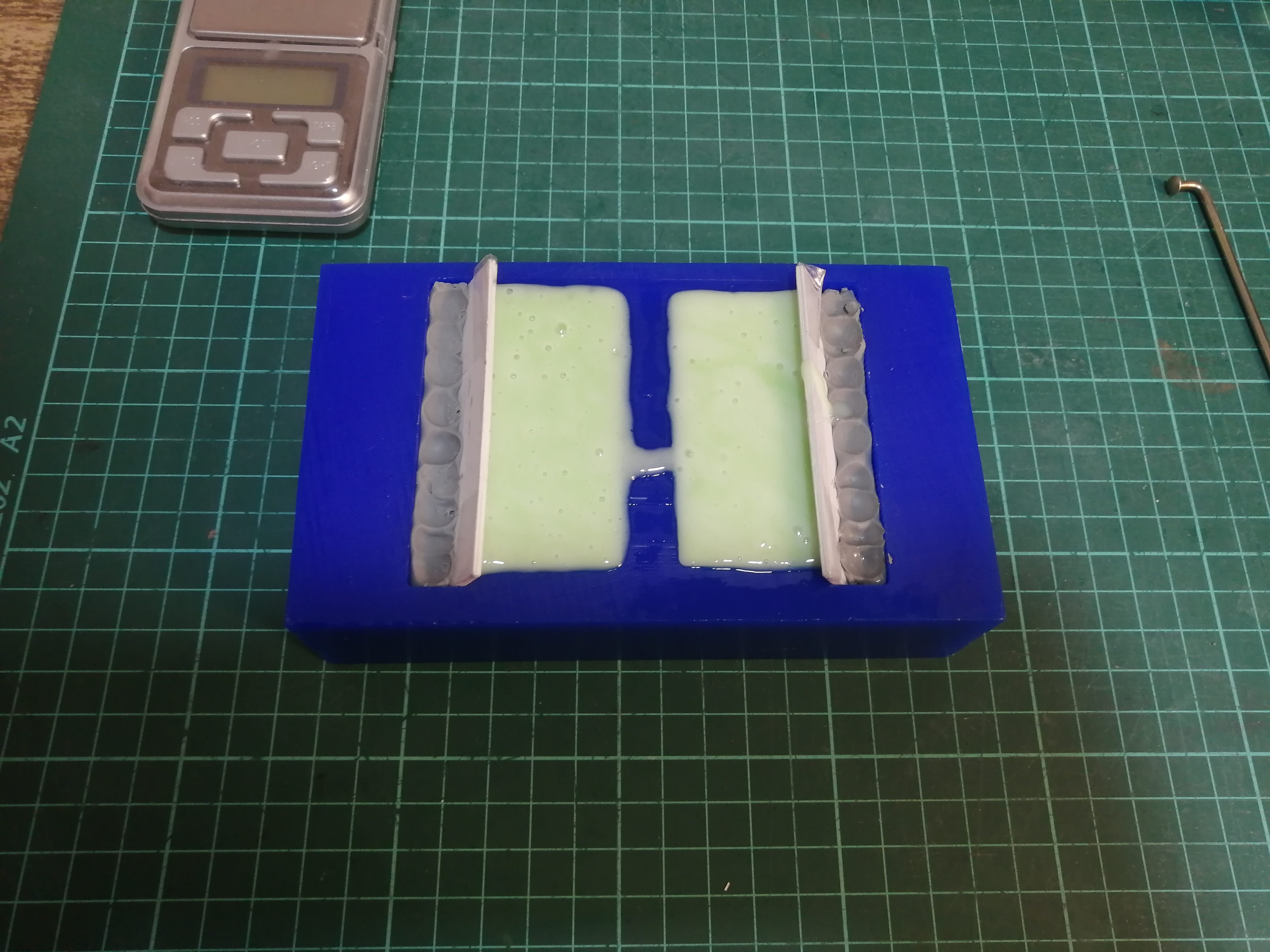
After the two molds are set I mixed around 85gr of RVT silicone with some food coloring dye and 3% of the hardener agent.
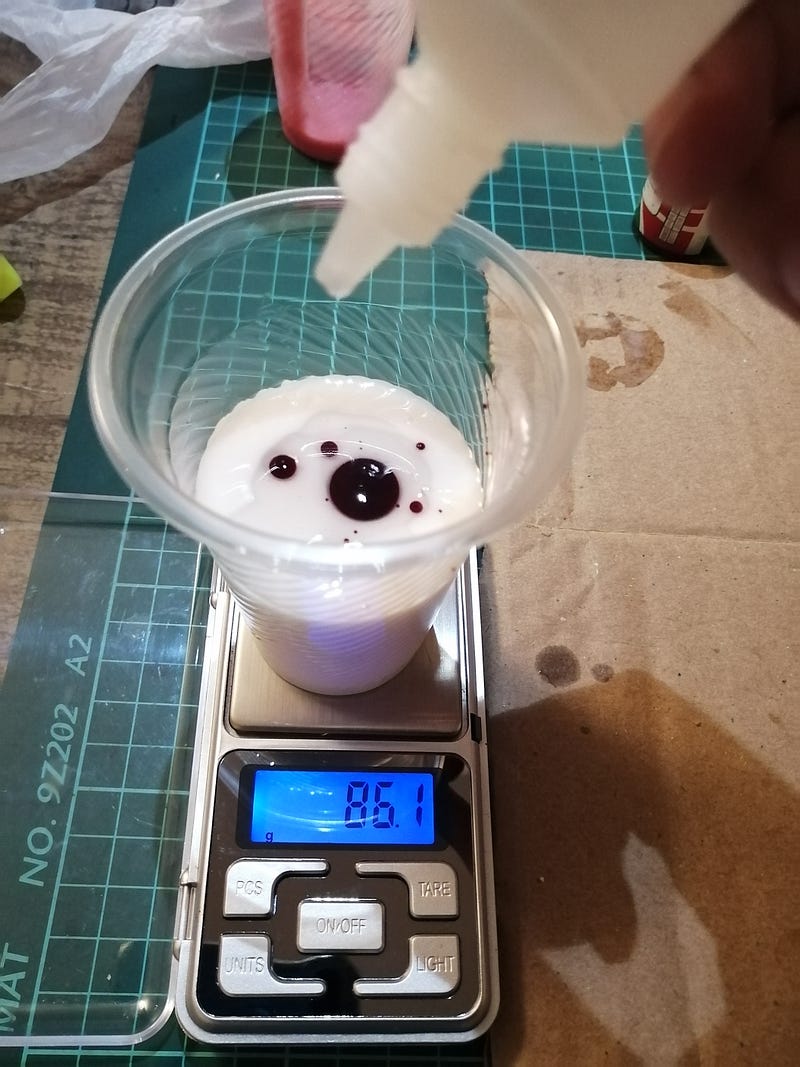
Yup, there's a lot of bubbles on that silicone! My mixing technique is not quite good yet. For the second mold, I got distracted and wait too long before pouring the silicone and had to force the silicone to fill the mold as it was getting almost solid.
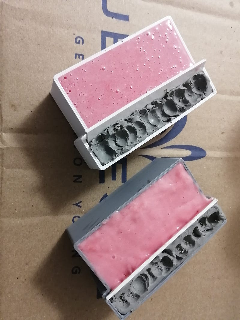
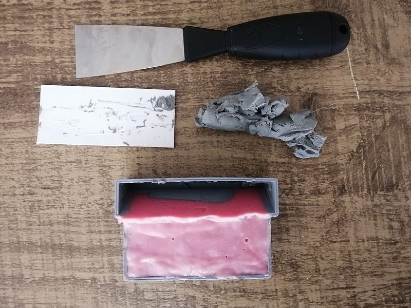
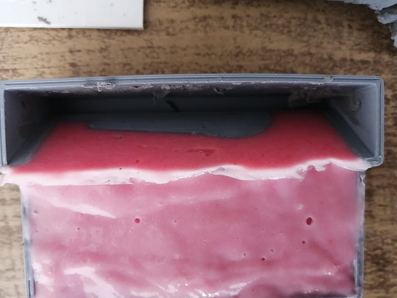
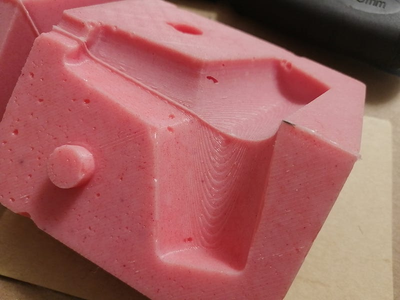
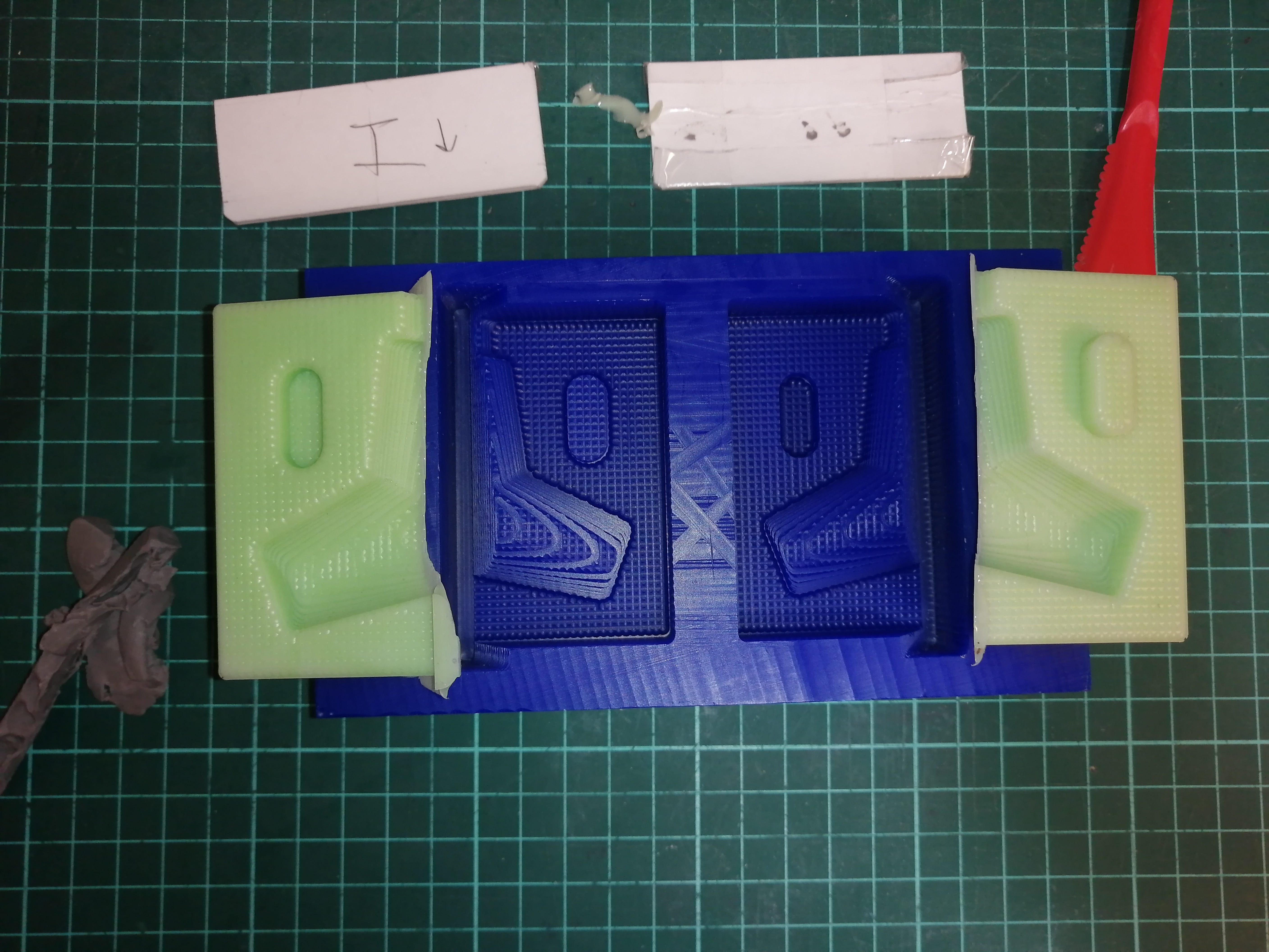
After 6 hours I scraped the plasticine out of the mold and took out the cardboard, this was a bit tricky, maybe I'll go easy on the plasticine for the next attempts. The side that is next to the cardboard went really smooth and the gap makes it easy to demolding.
This is a close-up of the cardboard edge:
These are the final casted molds, these will go together to make 1/3 of the final silicone mold, so there's more silicone pouring to go!
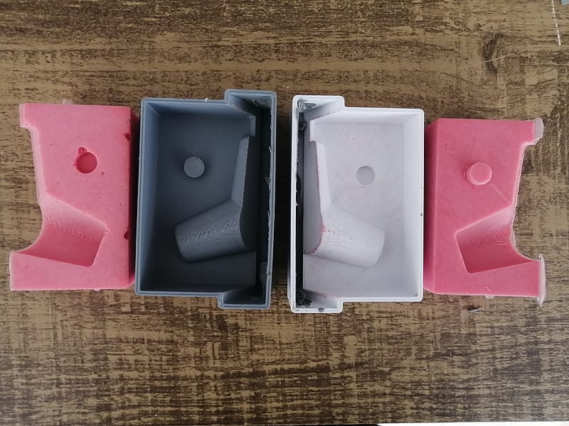
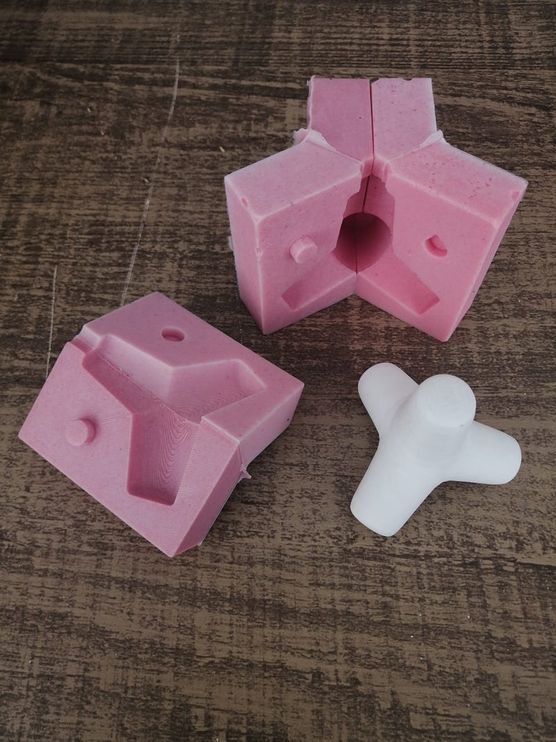
I got an unexpected solution to joining the two parts, at first I thought to join them by the registry key, but as an accident, I joined the two by the smooth face (the one that was cast on the cardboard) as this side was sooo smooth, it almost glued the silicone together making the two parts a solid one!
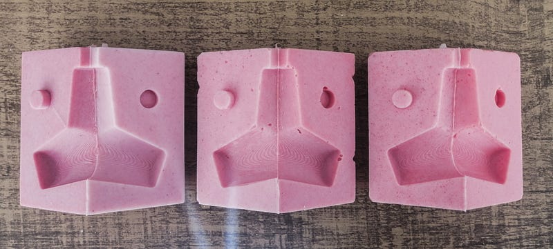
These 3 identical parts make the final casting mold and a little example of how these should go together.
An issue with this type of mold joint is that is very difficult to correctly align the seams because they form sharp corners. I also used a very soft silicone (around 20A, but I cannot be sure because it had no label) that makes this worse. The registry keys don't help that much (or at all) maybe I'll need to make them bigger for the CNC milling, or use the smooth silicone on silicone technique that I discovered by accident!
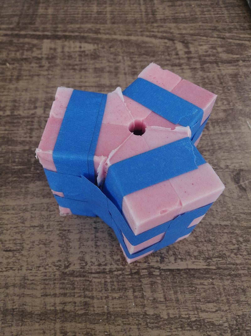
Securing the mold for the casting with blue tape is not the best option because the tape doesn't adhere to silicone at all, so I had to tape several sides to hold it together, even then I noticed that at the base, where the three corners meet still has a tiny hole. A better option is to make a custom laser-cut box to contain the silicone mold.
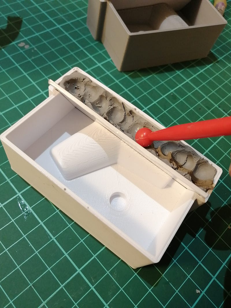
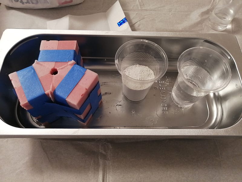
I only got plaster as casting material, this is not the best option, but it's more than enough to see if the molding works. The mix is a 2:1 plaster to water ratio. I sprayed a little alcohol inside the mold to help bubbles break if formed.
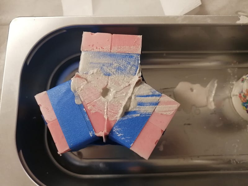
Plaster is very quick to cure, taking around 30 minutes, but I made the mix with a little too much water so I've waited a couple of hours for demolding just to be sure.
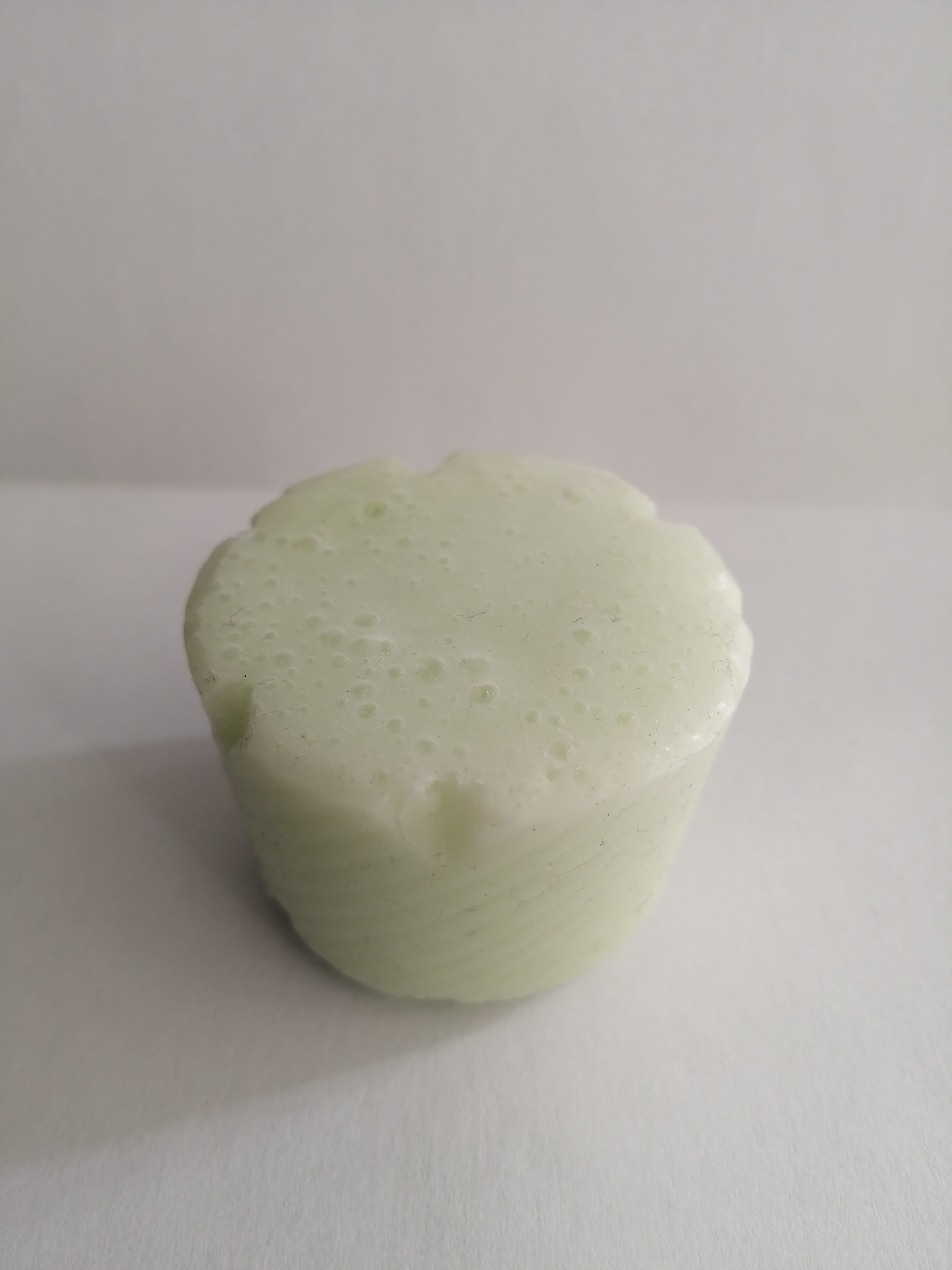
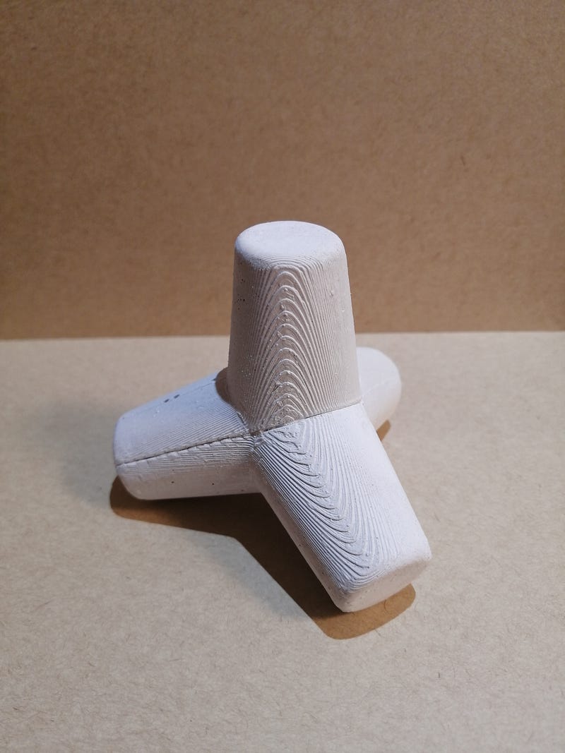
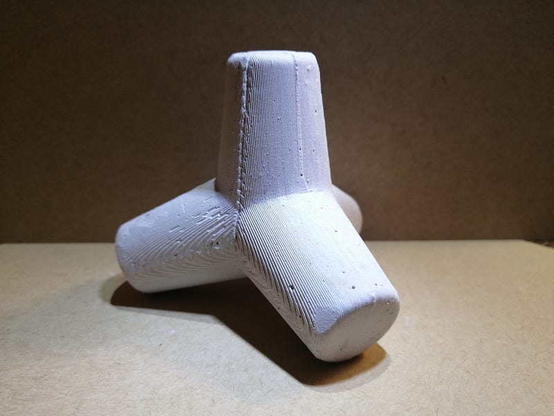
This piece makes a nice paperweight so next time I’ll be casting it in concrete! The 3D-printed molds gave it a nice texture. Hero shots for the FabGram:
Molding and Casting! (now with wax block)
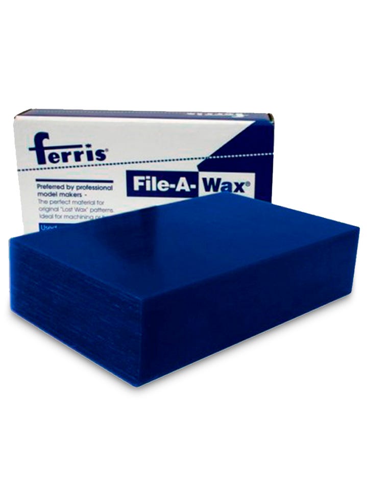
Now the Fablab is partially open (I can not go, but the instructors can) I can finally make the mold as intended, I bought a 1Lb Ferris machining wax but somehow this ended up being smaller that the one considered for the design, so I’ve adjusted some measurements.
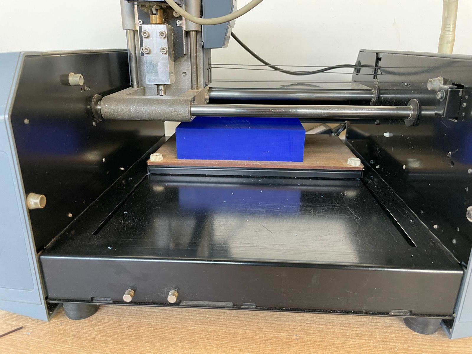
The setting up is pretty straightforward, the wax block is secured by double-sided tape to the machine bed, and the Z-axis setup process is the same as the electronics production.
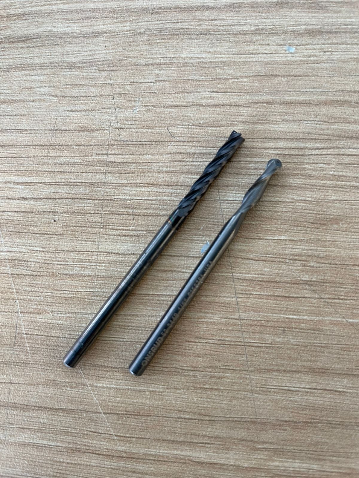
The bit I’ll be using are 1/8" flat for the roughing pass and a 1/8" ball end for the smooth pass.
A little test for the Z setup and the work is ready to be sent! The first pass is for roughing, which creates these little rectangular steps and it took nearly an hour.
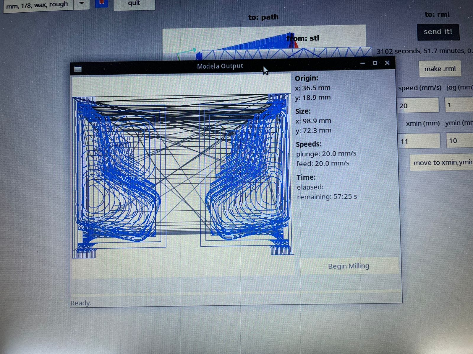
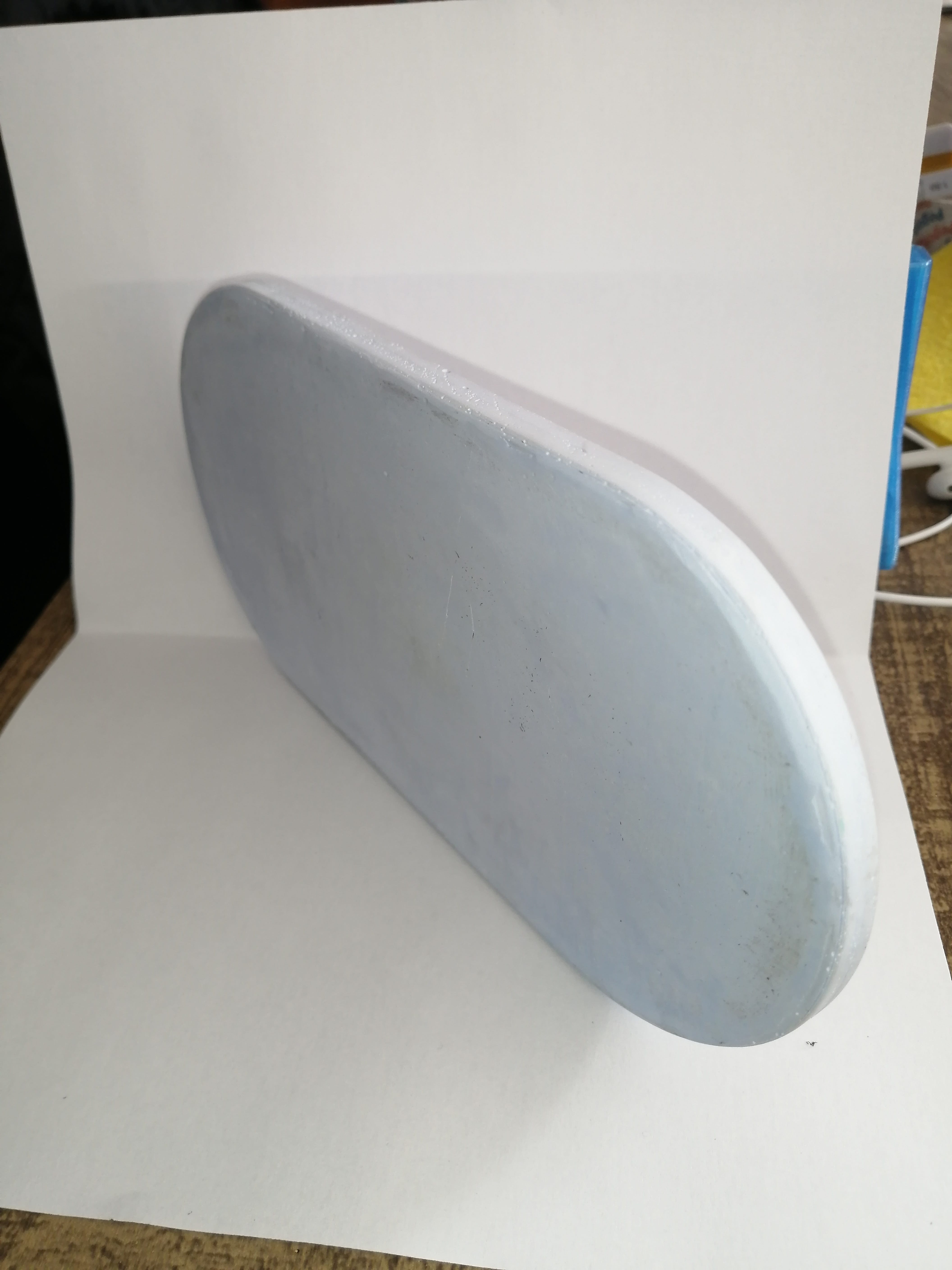
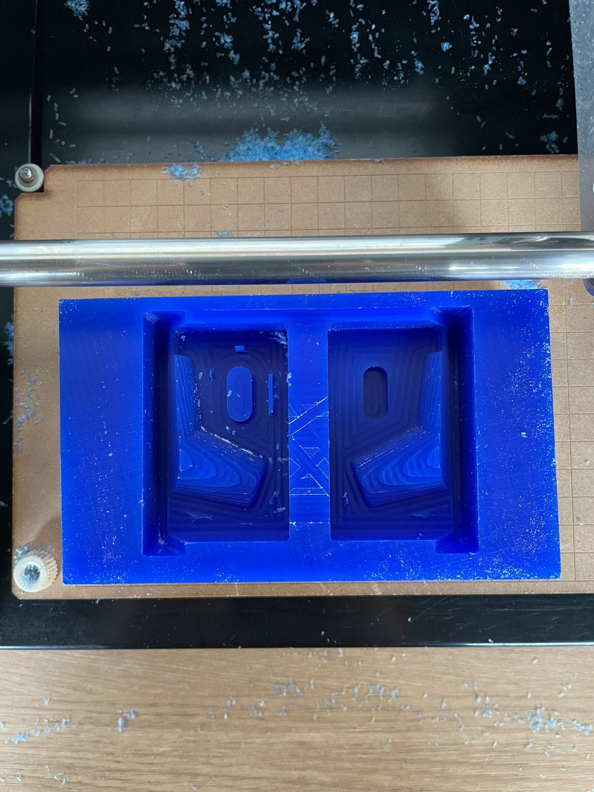
This is the result after the job was done. It showed quite clearly the final shape.
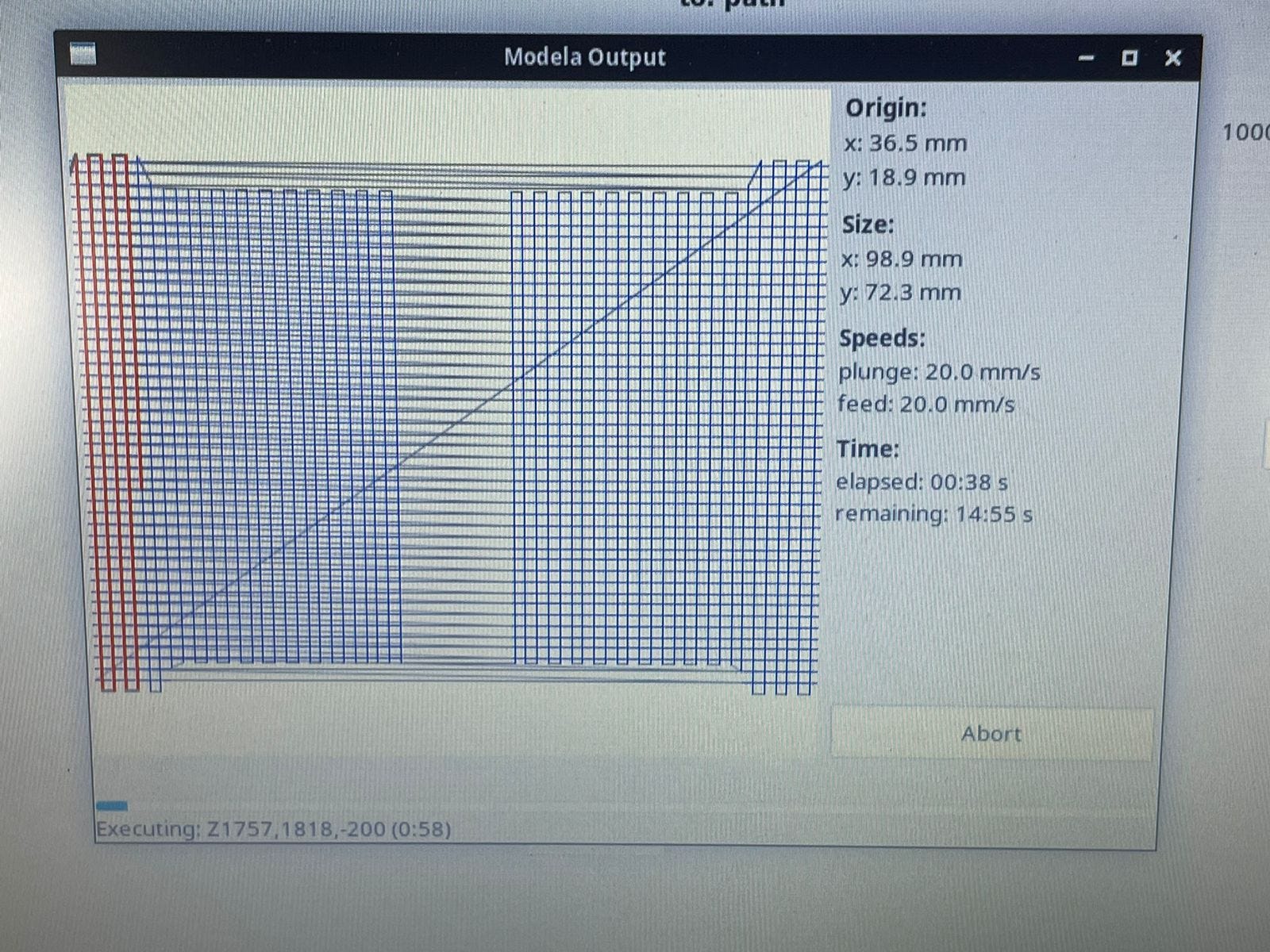
Next, we repeat the process for the smooth pass using the ball end mill. The pattern looks different this time, looks like it will only do vertical passes? Im not sure.
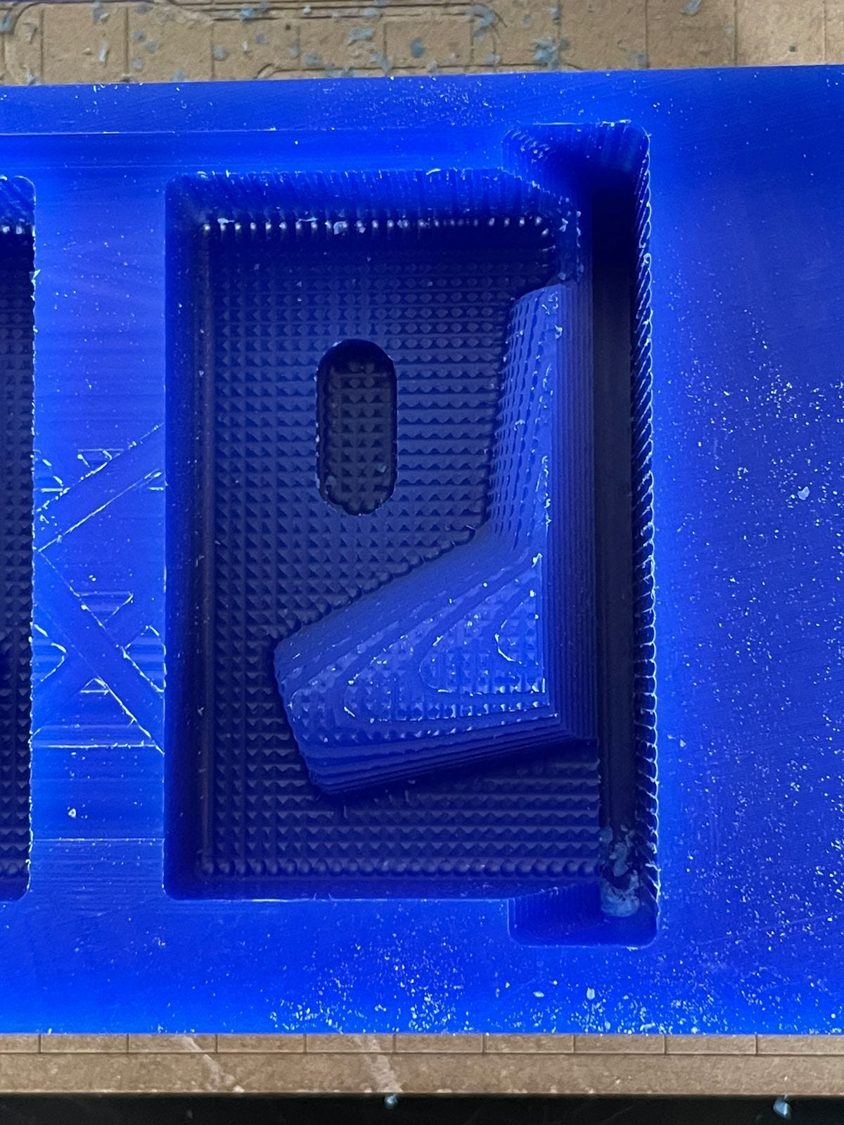
This time the result came not as expected, the surface is not smooth as it has some small pyramid-like protuberances, This might be because the steps are not close enough or it's missing the horizontal part of the passes? As I was not conducting this milling work I am not sure how the machine was behaving, I asked the instructor but he wasn't sure what was wrong either.
I’ll try to make the molds with silicone but as the final form is quite complex I am not sure the mold parts would be fitting tight enough due to the protuberances. Also, the casting would reflect this bumpy pattern.
The process for the mold is the same as explained before, The molds are complete with a cardboard piece to get that undercut covered. The cardboard is wrapped on plastic tape not to stick to the silicone. To keep the cardboard in place I added some plasticine between the cardboard and the mold and pressed it to make a tight fit.
After this, I measured the volume with rice and marked a plastic cup, this ended up being around 90gr of silicone for the two parts.
I added a little green pigment to the silicone to see the mixing clearly. After mixing the silicone I poured it into the wax block.
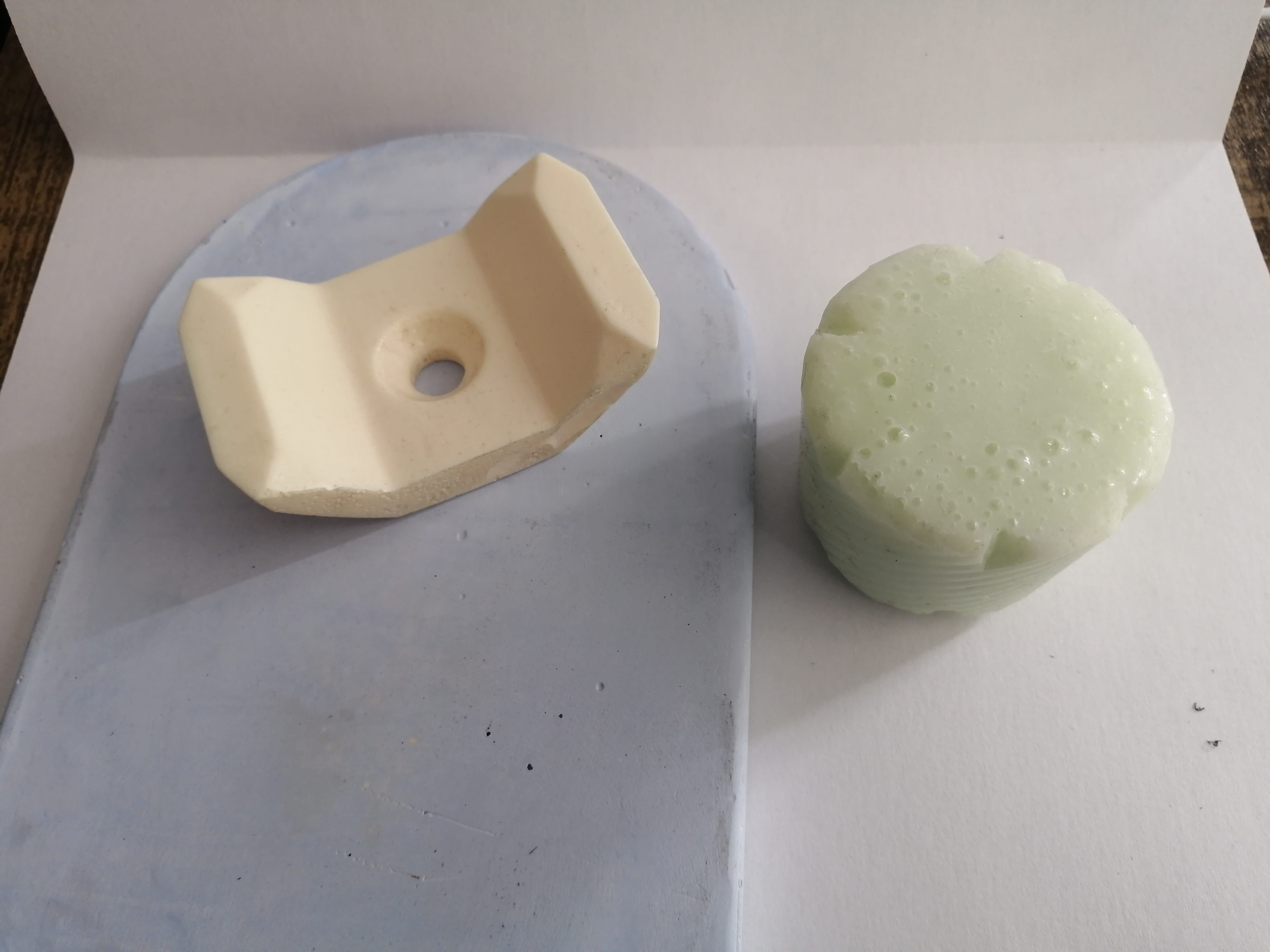
After 4 hours it was ready for demolding, I checked the mixing cup to make sure it was ready! The cardboard is kind of hard to take out, but I am careful not to damage it to use it for the next mold. I can already see some flashing that went under the cardboard as the surface is not flat, but this residue is minimum and easy to clean.
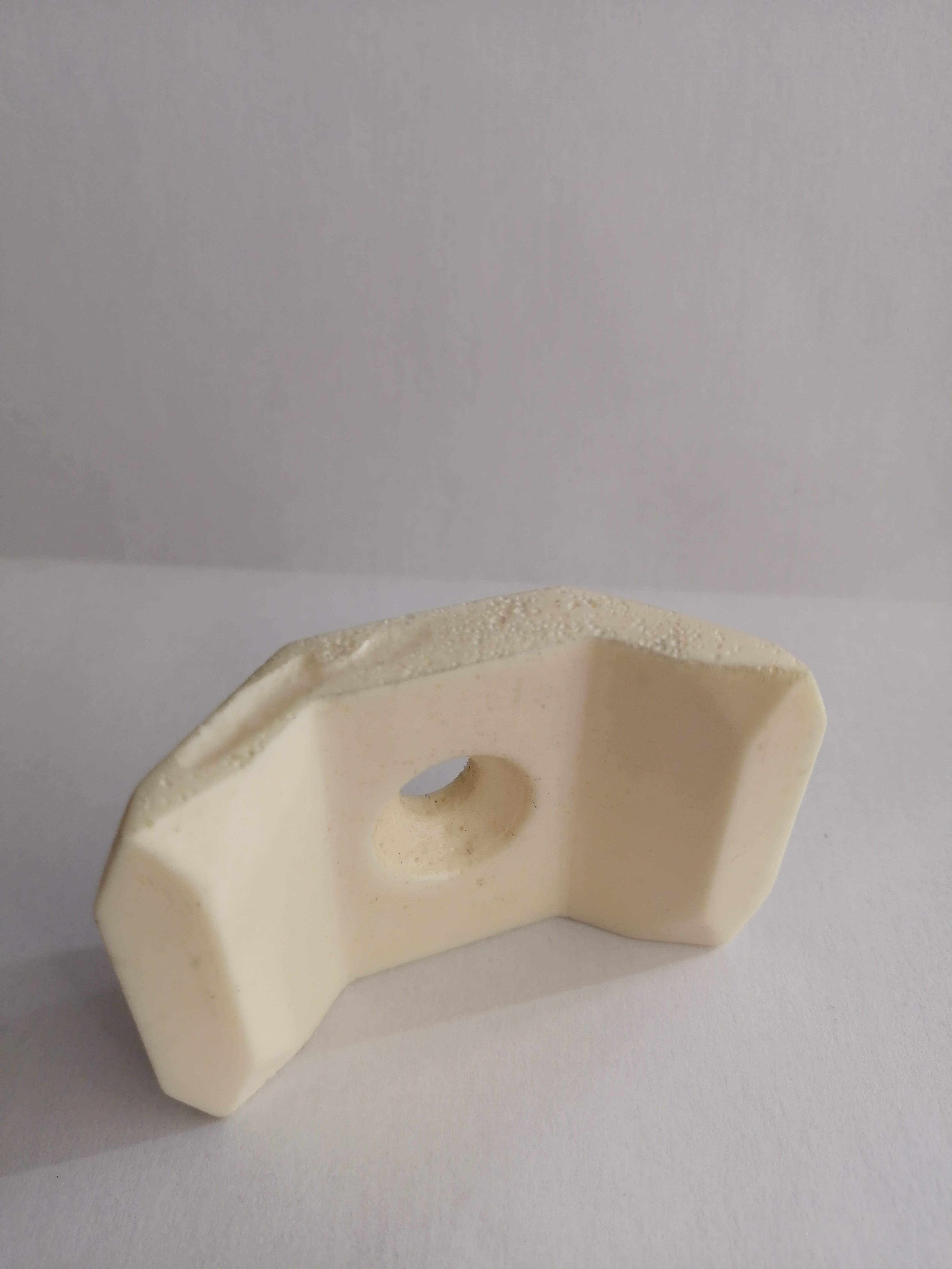
I relieve both of the molds and these look very good
The inside surface is clean and with no bubbles, here you can see the flashing better, both parts came out looking good. The bumpy pattern did translate to the silicone.
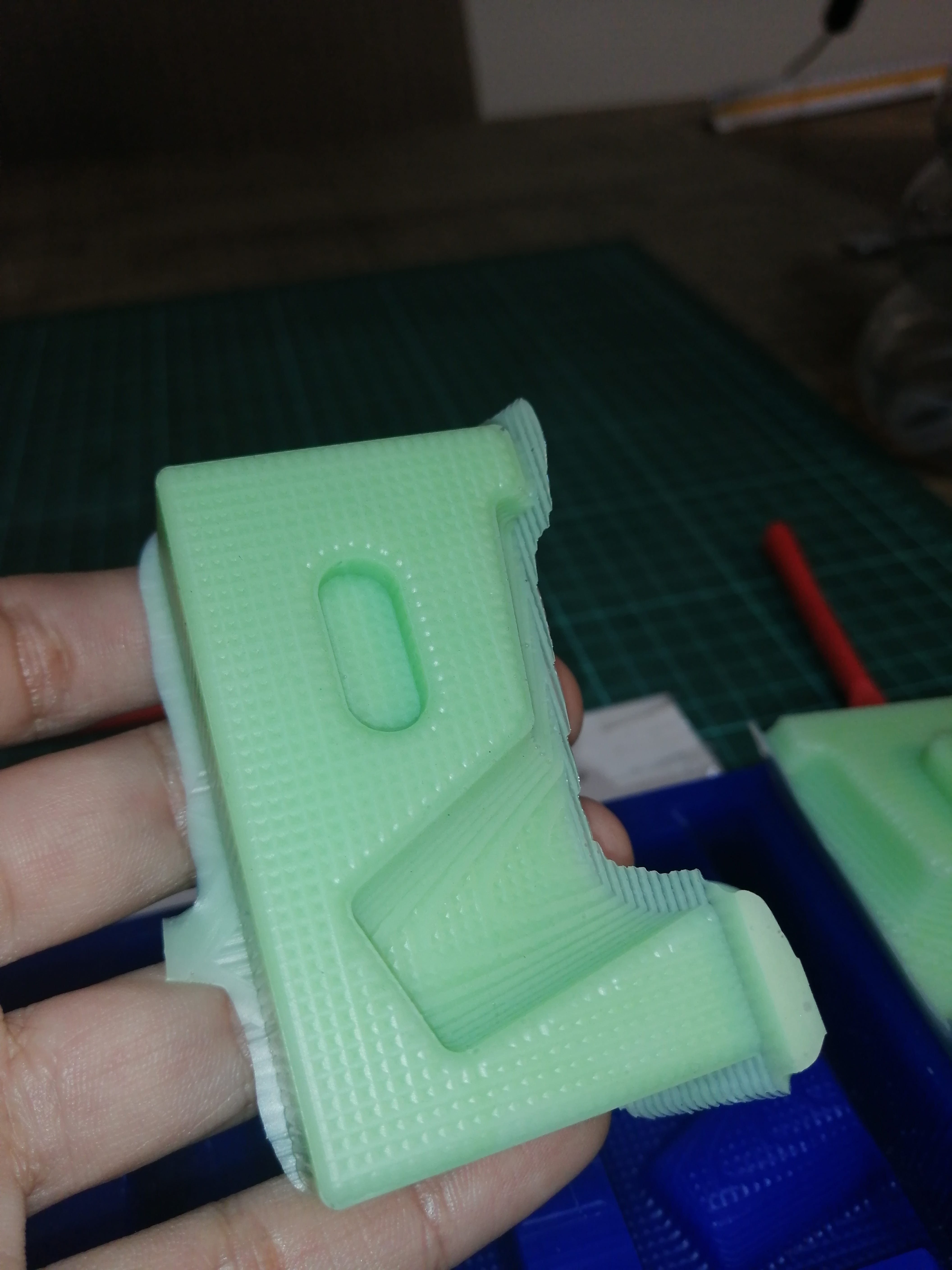
After cleaning the flashing, these parts are ready to be assembled, both parts make 1/3 of the complete mold.
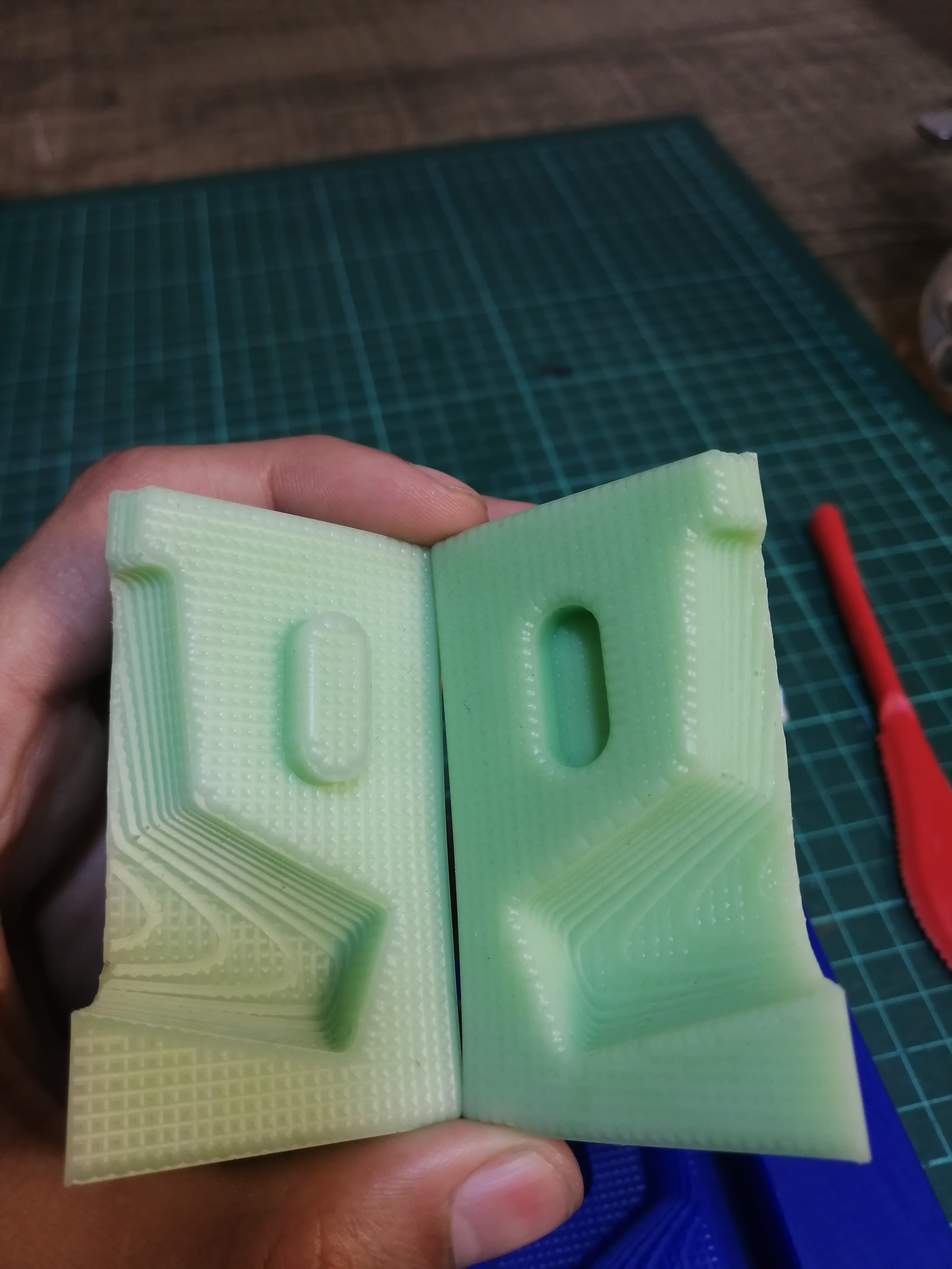
I am using the trick explained before, joining both parts by the smooth side (the one that was cast against the cardboard) these two stick together as one piece.
Molding at home
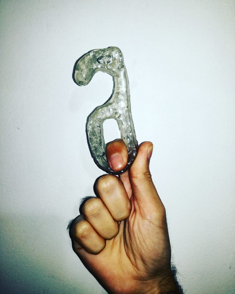
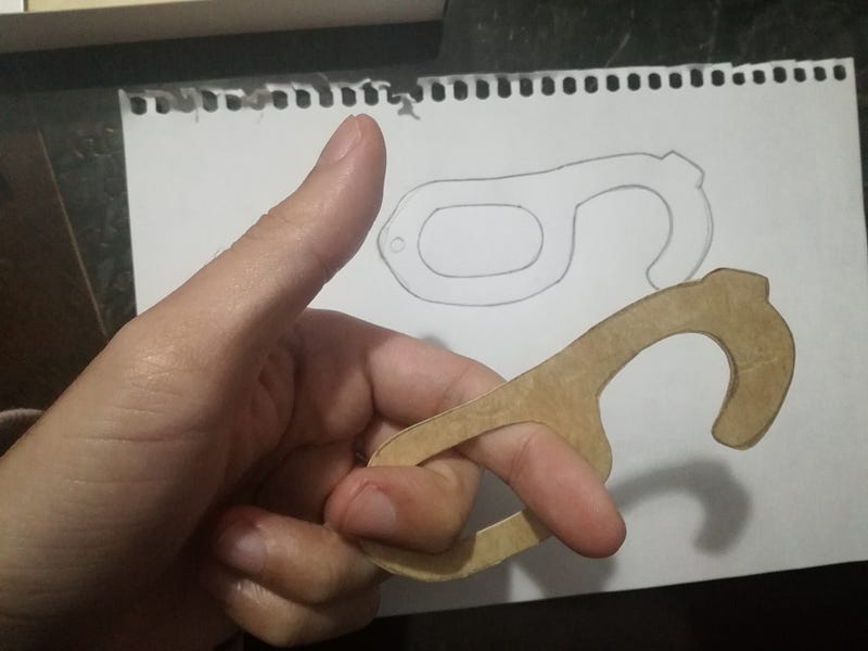
As the lockdown is still enforced in Peru I decided I’ll be trying to make a non-touch door opener with some photocuring resin I’ve got from the Fablab before it was closed and some household items to make the mold.
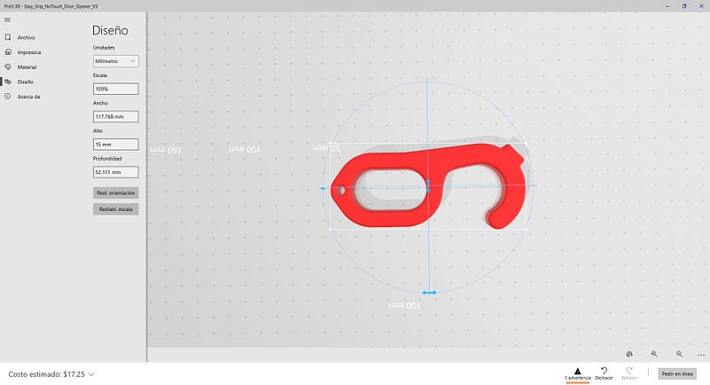
The model I selected is available on Thingiverse as an Easy Grip No Touch Door Opener.
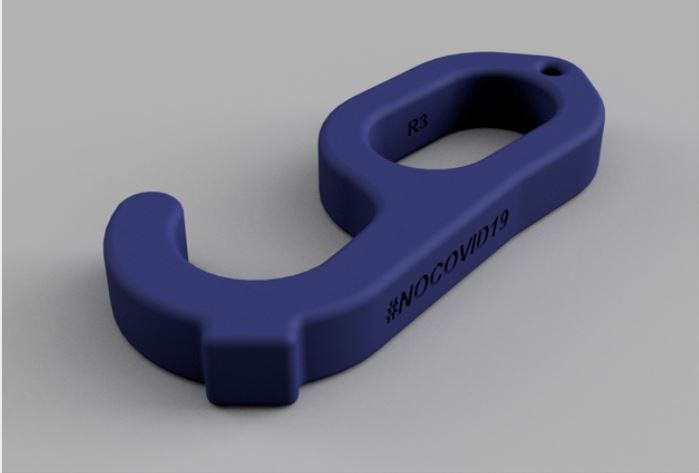
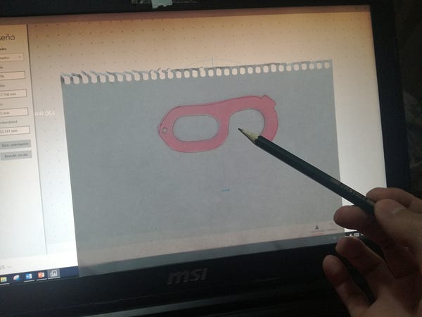
Download the .stl file and open it with windows 3D viewer. I copied the silhouette from the screen with a pencil and paper because I do not have a printer.
I’ll be using a cardboard template to form the mold
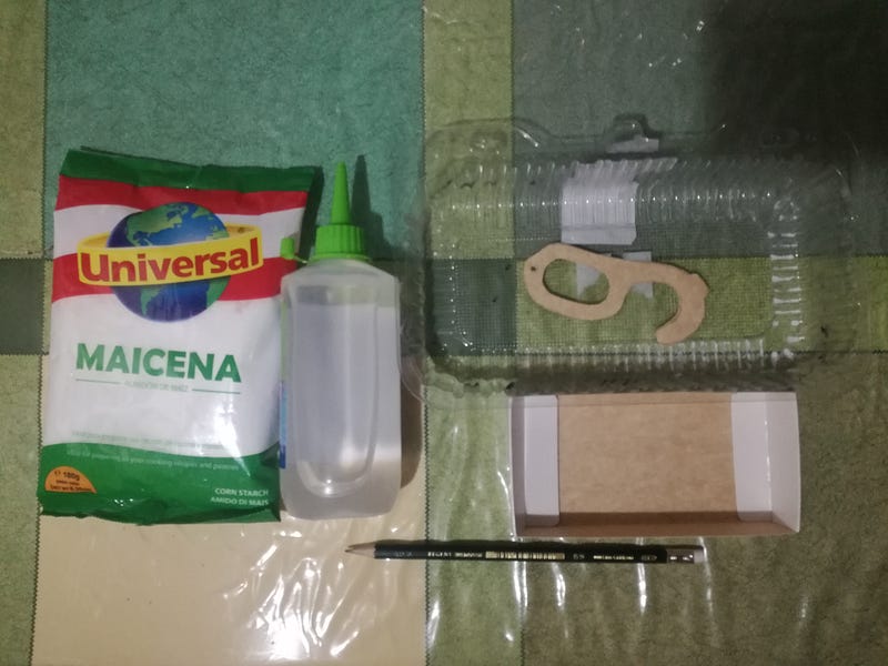
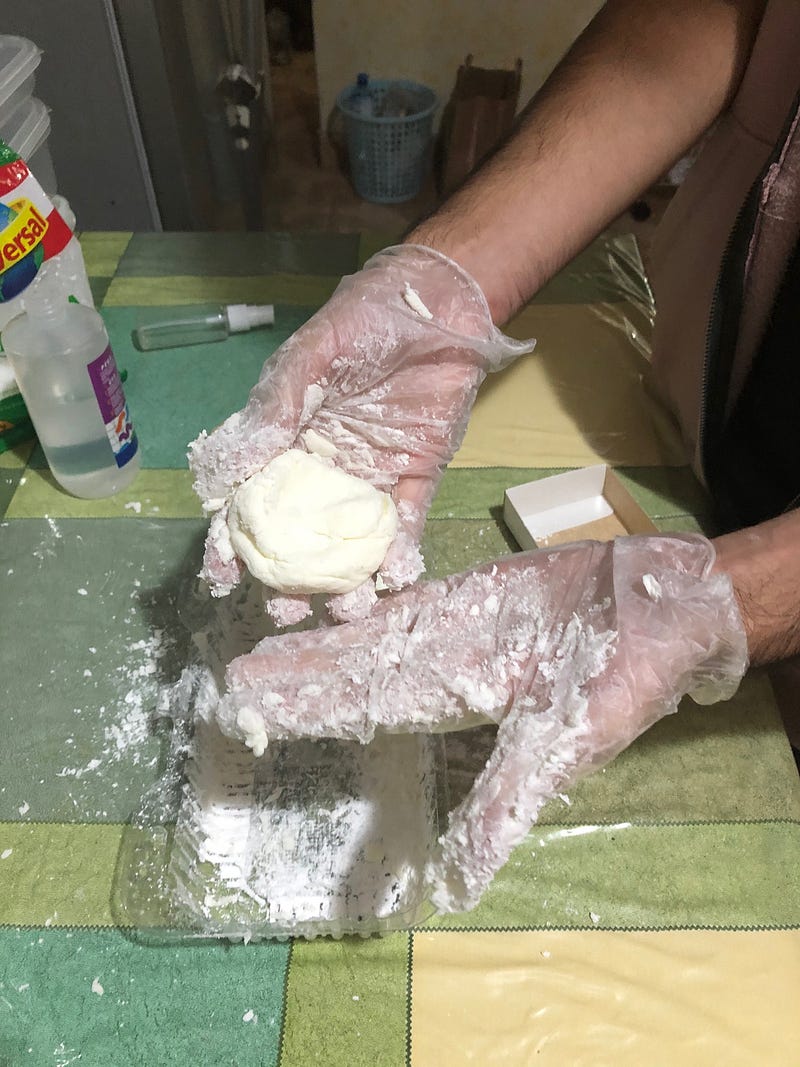
For the mold, I’ll be mixing some cornstarch and glue (known as liquid silicone here in Peru). The mixing begins by pouring cornstarch in a recipient and adding a generous amount of glue, try to cover all of the glue with cornstarch and keep adding it and knead it until the mix is not sticky.
It should have a plasticine-like consistency. As this is the first time I tried this combination, I was not sure of the proportion of glue and cornstarch (or if it would work at all) but this was around 125ml of glue with nearly 150gr of cornstarch.
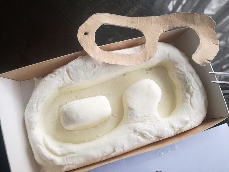
I placed this dough in a small cardboard box and proceed to press the cardboard template with the pencil to make the shape, I was trying to get all the edges flat.
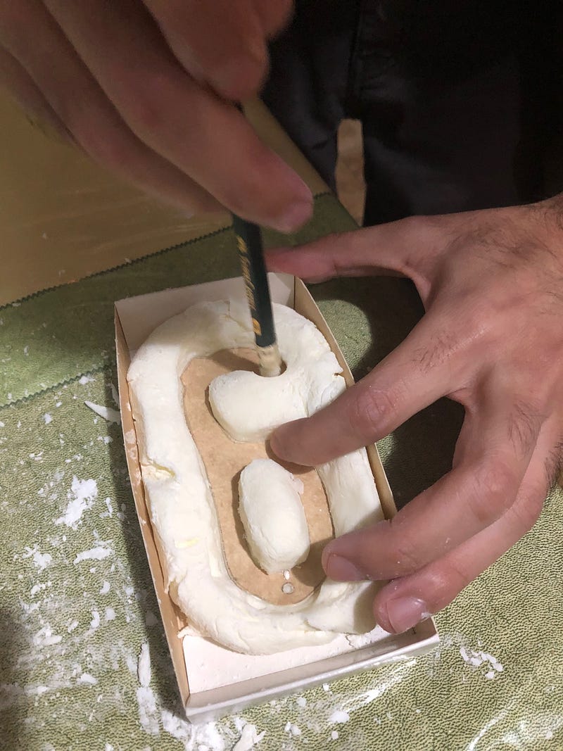
The dough was moldable enough to make this an easy process and maintained the desired shape with little contraction of the mold. I let it dry for the night.
By the next day, it was quite solid, and I supposed this combination was not very good after all because it would break as the casting is released. I took out the cardboard template from the mold with the help of tweezers and it teared up bits of the mold on the edges, so we’ll be not having a smooth surface finish after all.
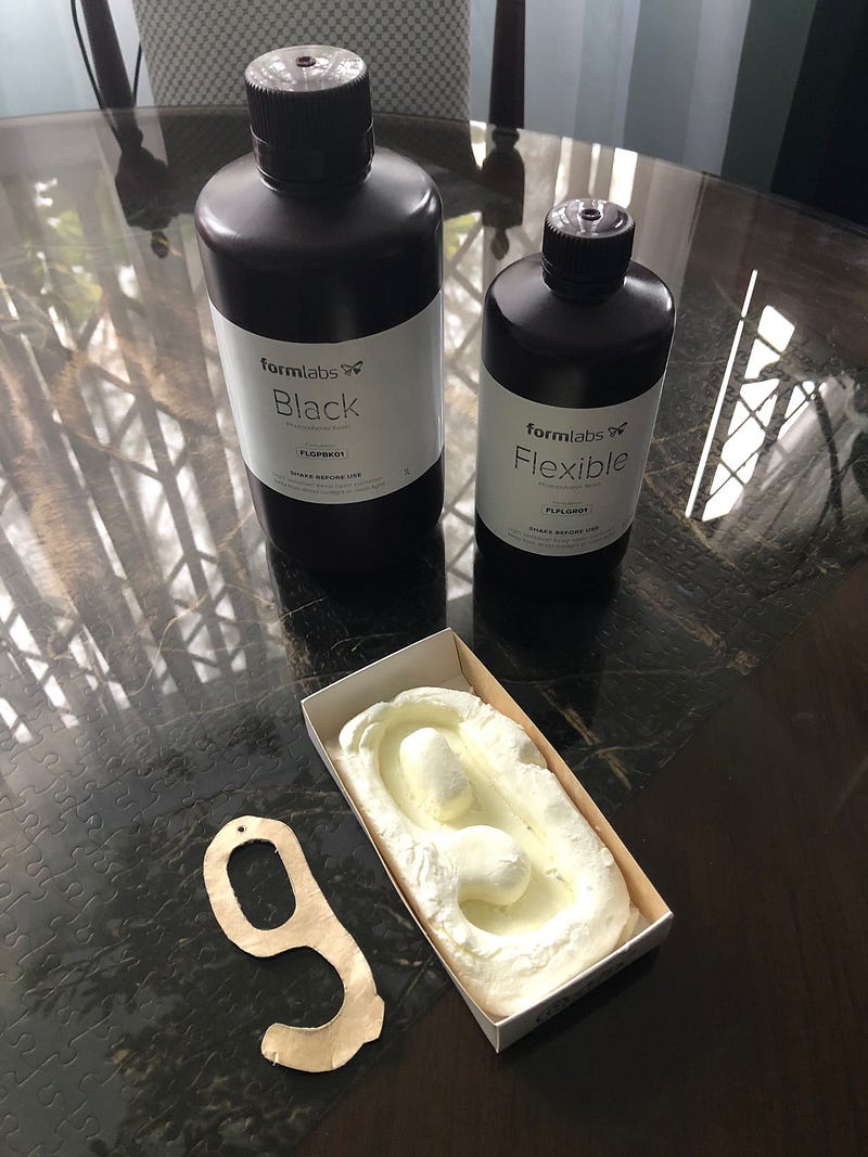
For the casting material, I’ll be using some photocatalytic resin from Formlabs (yes, the one that is used with 3D printers) and try to cast them with the help of the sun.
So here are the safety sheets for each product (.pdf):
- Black Resin FLGPBK01
- Flexible Clear Resin FLFLGR01
Both have the same warnings related to irritation to the eyes and skin.
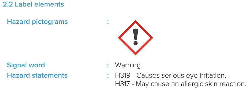
The recommendations include wearing protective gloves, eye or face protection, and avoid breathing vapor.

Warning: These resins were already past their expiry date by almost 2 years, but I did not want to let them go to the trash without some experimenting first. I already made some tests with a small amount and making it cure exposed to sunlight, this worked surprisingly well taking into account this is expired material.
I’ll be using the flexible clear resin because this could be cast in a bigger volume than the black. Black resin needs to be cast layer by layer, allowing it to cure between layers. While the flexible resin lets the sunlight go through the whole cast.
So wearing our protective equipment, and being safely outside the pouring begins!
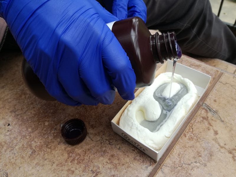
Unfortunately, It’s been cloudy the last few days, so we’ll see how it’ll cure without direct sunlight, fingers crossed!
After 3 cloudy days, the resin has finally cured!