The assignment goals
Group assignment:
Design a machine that includes mechanism + actuation + automation
Build the mechanical parts and operate them manually.
Document the group project
Individual assignment:
- Document your individual contribution.
Group Assignment
I was in charge of the overall design of the machine, so you can see the detailed development of the idea as follows in the individual assignment section of this page.
Sadly, the other group members choose not to participate in the development of the assignment so I ended up alone with the machine but I can say it was a fun challenge!
The idea
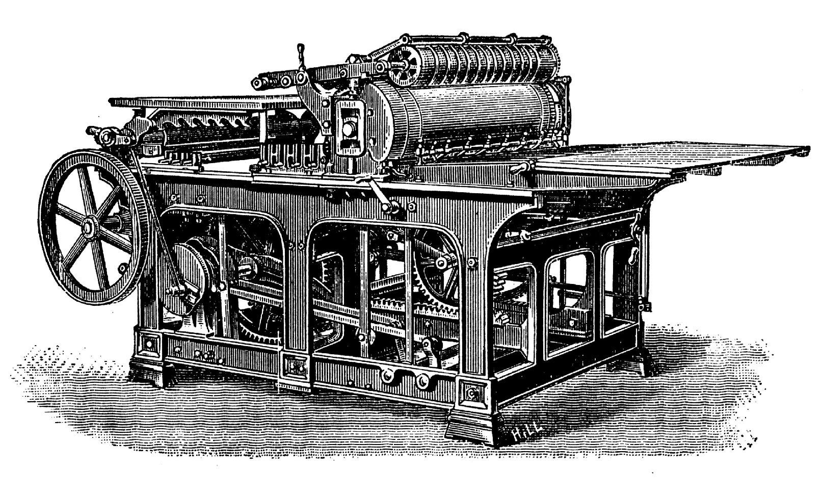
To design an Automated Printing Press, but tiny. This will work by moving a bed holding the matrix with the design and the paper to be printed under a roller, the pressure will print the image to the paper. I hope to create multicolored prints with additive matrices.
This is my first time doing anything printing-press-related, so let's see how it goes!
The open press project is a good example of what I want to achieve.
Manual operation
The main part of the machine is the sliding bed, the first test proved that the channels and bearings were in a good position to allow a complete and smooth movement of the bed.
By this point, there was no group, so I'm uploading all the documentation of design, fabrication, test, and programming to this page. The final video is at the bottom. Enjoy!
Team planning, executión, and building of the machine
By this point, there was no group, but I'm still required to show some team planning by the Nueval standard so I'm uploading all the documentation of design, fabrication, tests, and programming to this page. The final video is at the bottom. Enjoy!
Programming
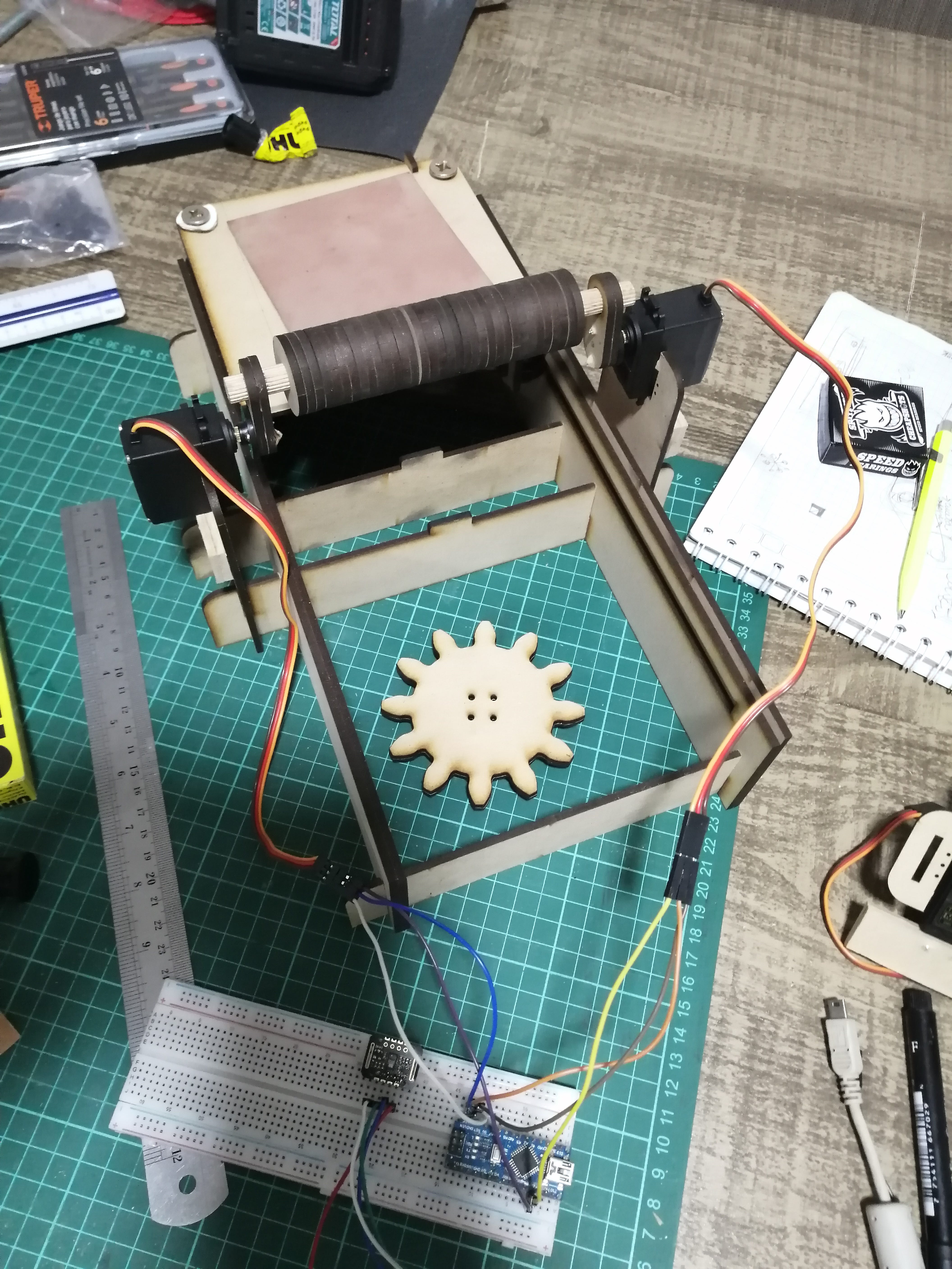
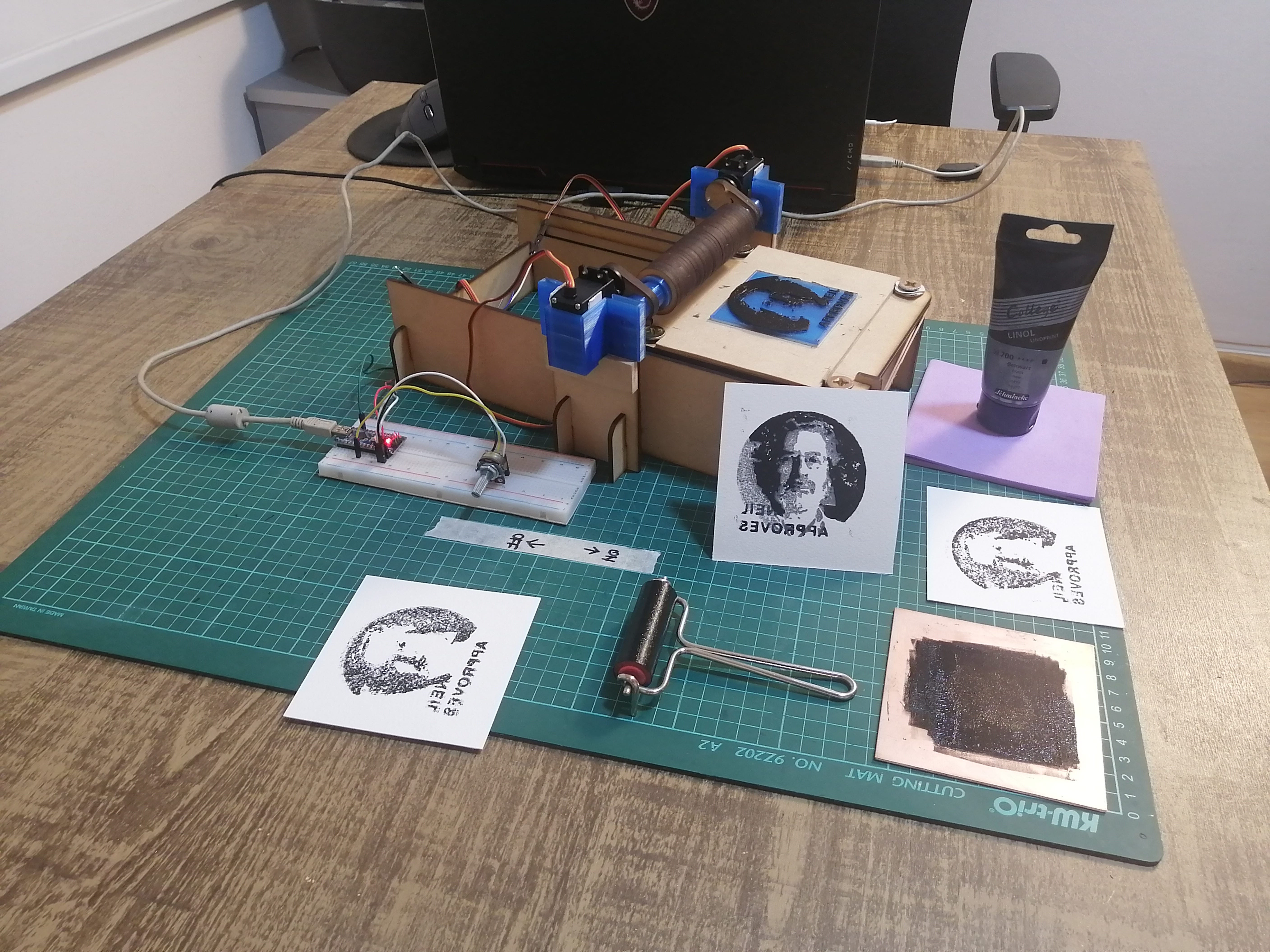
The machine operation is quite simple, We got tree servos that move in a predetermined sequence. So we define a witch and the servos left, right, and base.
First, we activate the sequence with a potentiometer (I didn't have a switch on hand) so The sequence starts when the potentiometer hits a certain position. We can see this value in the monitor. this causes the servo left and right to synchronize at an upright position, and after a short delay, the servo in the base does a 0 to 180 movement, making the base and the place move under the rolling cylinder.
All is controlled with an Arduino Nano, and you can download and check the code in the download section at the bottom of the page.
Problems and posibilities
The first problem was that I begin the design considering that FabLab would provide some micro servos for the movement, so I downloaded a 3D file and designed around it, I ended up receiving bigger servos but the MDF pieces were already cut. The Fablab is closed for the holidays so I modified the structure with a cutting blade and some extra 3D printed parts made at home to secure the new and bigger servos.
In future development, the programming of the machine needs to be improved. I was working with a Arduino Nano with direct USB current from my PC but this was not enough to move the 3 servos, well not even 2 of them simultaneously, as I got some wonky movements when I tried. Maybe a dedicated power supply for the servos is needed.
This would make it possible to synchronize the roller movement to firmly press the paper to get better printing results.
Another improvement could be made by having a stepper motor on the bottom instead of a servo, this would allow for smoother and slower movement of the bed.
The current servo worked well but had a little backlash that pushed the bed out of the machine, and sometimes jammed the mechanism. I fixed this issue by adding a 3d printed part that holds an elastic band once the bed is in place, this makes a little pressure on the rack and pinion mechanism neutralizing the backlash movement. You can see it working in the video!
Individual assignment
My contribution to the machine is the mechanical design, and 3D model visualization, this includes the proof of concept, fabricating the parts, assembling, and testing the prototype. Naturally, if anything goes wrong with the first design I would change it and test it again. Hope everything goes well on the first try!
Machine design
My new FabAcademy motto is “keep it simple”, so I’ll be using servo motors for the movement of the press. Maybe 2 or 3 would be enough. The mechanism would allow for the bed of the press to slide under a fixed cylinder that pushes the matrix and the paper together to make the print.
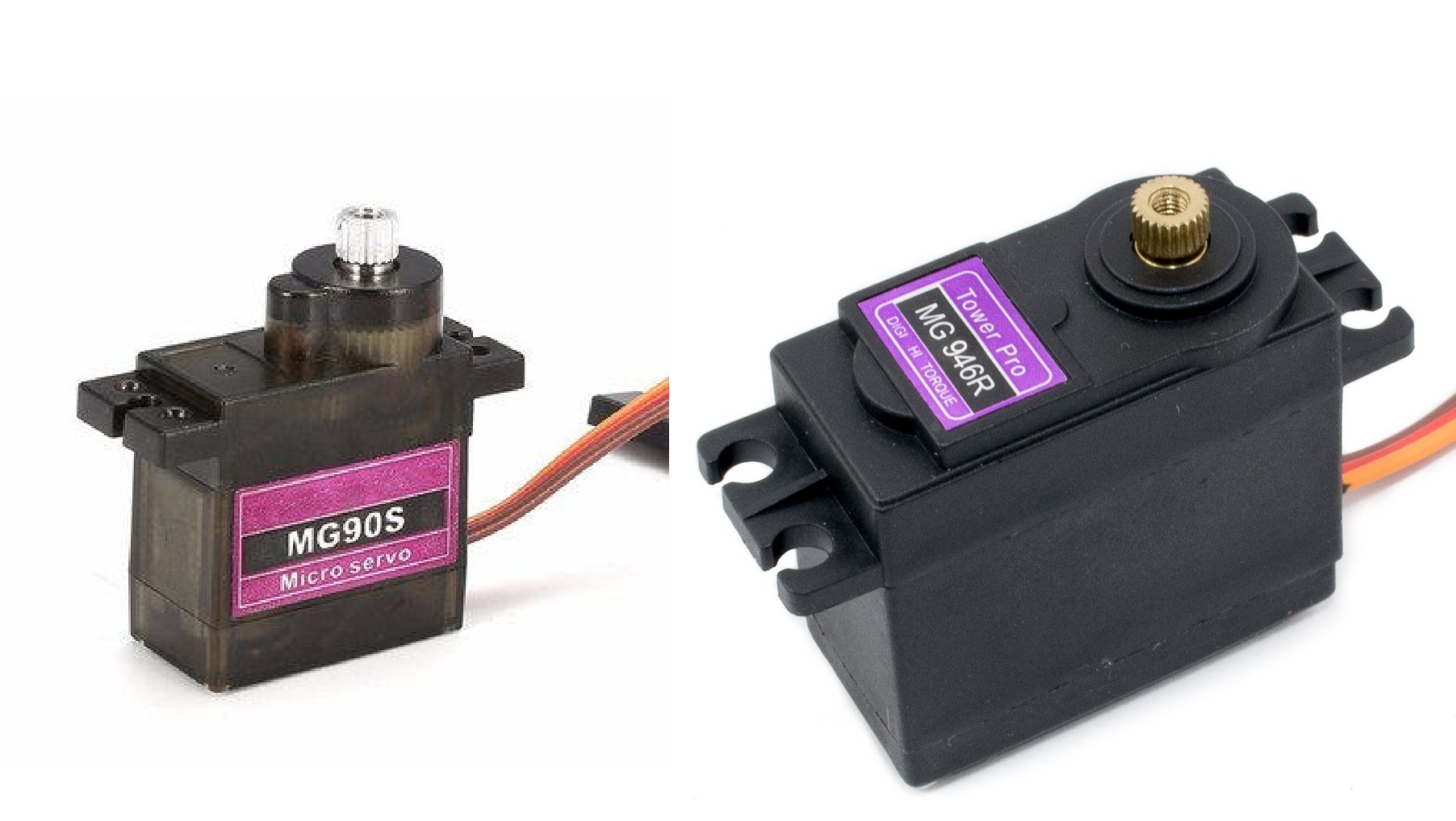
The problem is that servomotors (at least the ones available al the lab) are microservos and have a limited range of movement of 180° and are very small, so we need quick testing of these capabilities.
The best way to make the bed slide (linear movement) is to use a rack and pinion mechanism with the gear attached to the servomotor.
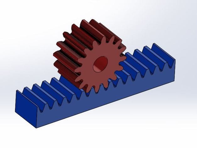
The first thing to prove it’s if the 180° degree movement of the servo does enough linear displacement for the bed to get a print, so I’ve used an online and free gear generator to make a quick rack and pinion model and measure the linear displacement.
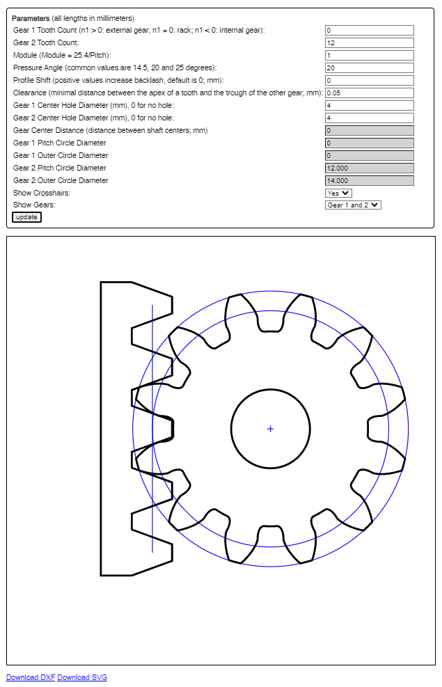
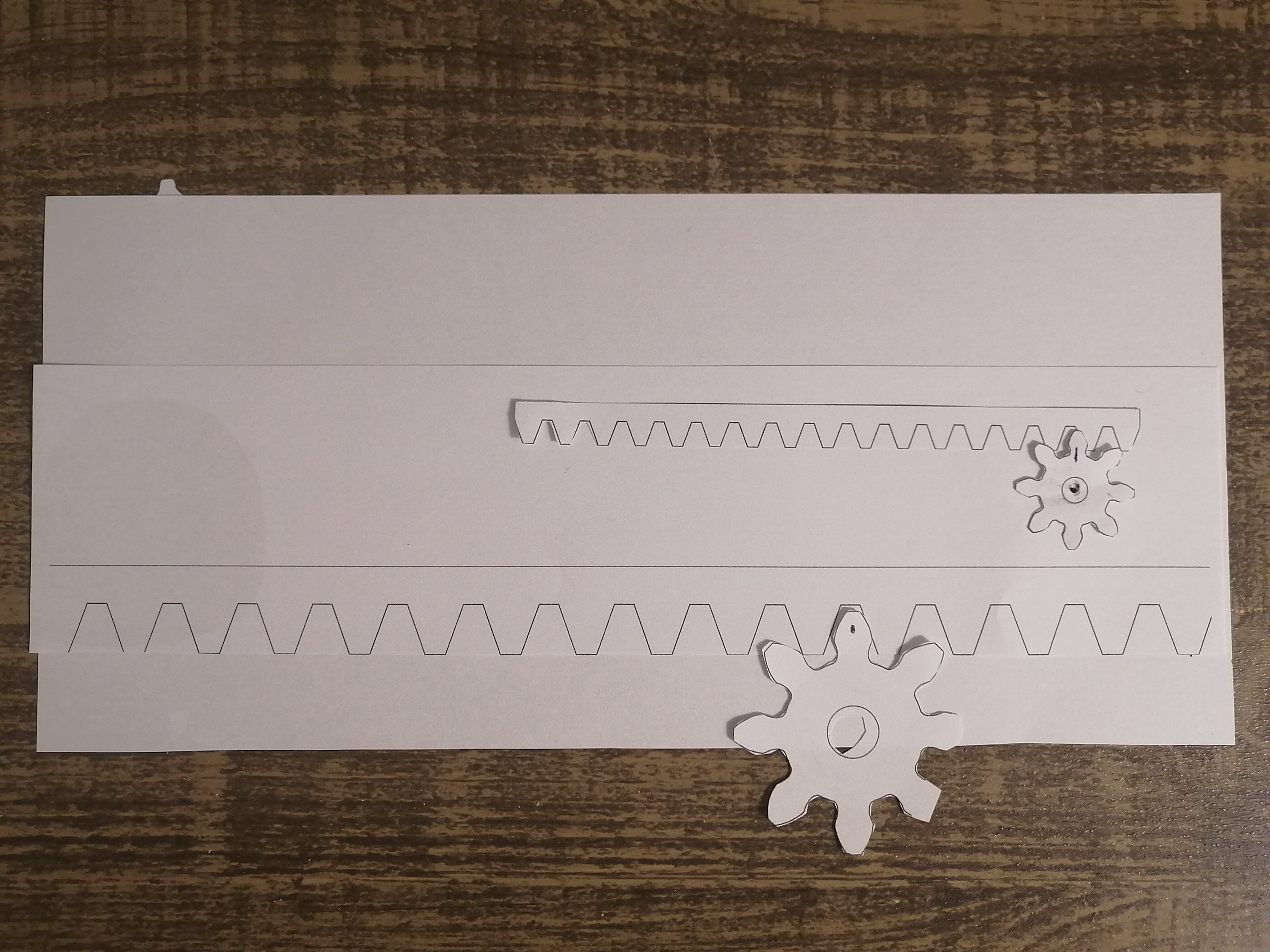
Because I don't have lab access yet, printed the gears on paper and simulate a movement, the goal is to get a movement of 10cm. On the first try, I printed the gear too small and got around 4cm movement, in the second test I scaled it to a 200% and got 8cm of displacement, so a scale around 300% should work to get a 12cm displacement.
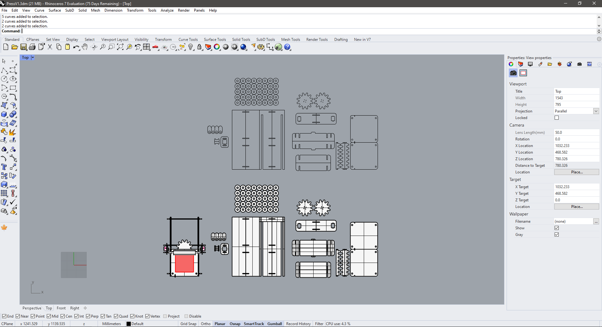
Next, I imported the gears to the design software and develop some ideas for the mechanism and the sliding bed. I already knew I’ll be using a servo (but not what type exactly for now) so I downloaded the Tower Pro MG90S model from Grabcad and placed it in the center of the arrangement.
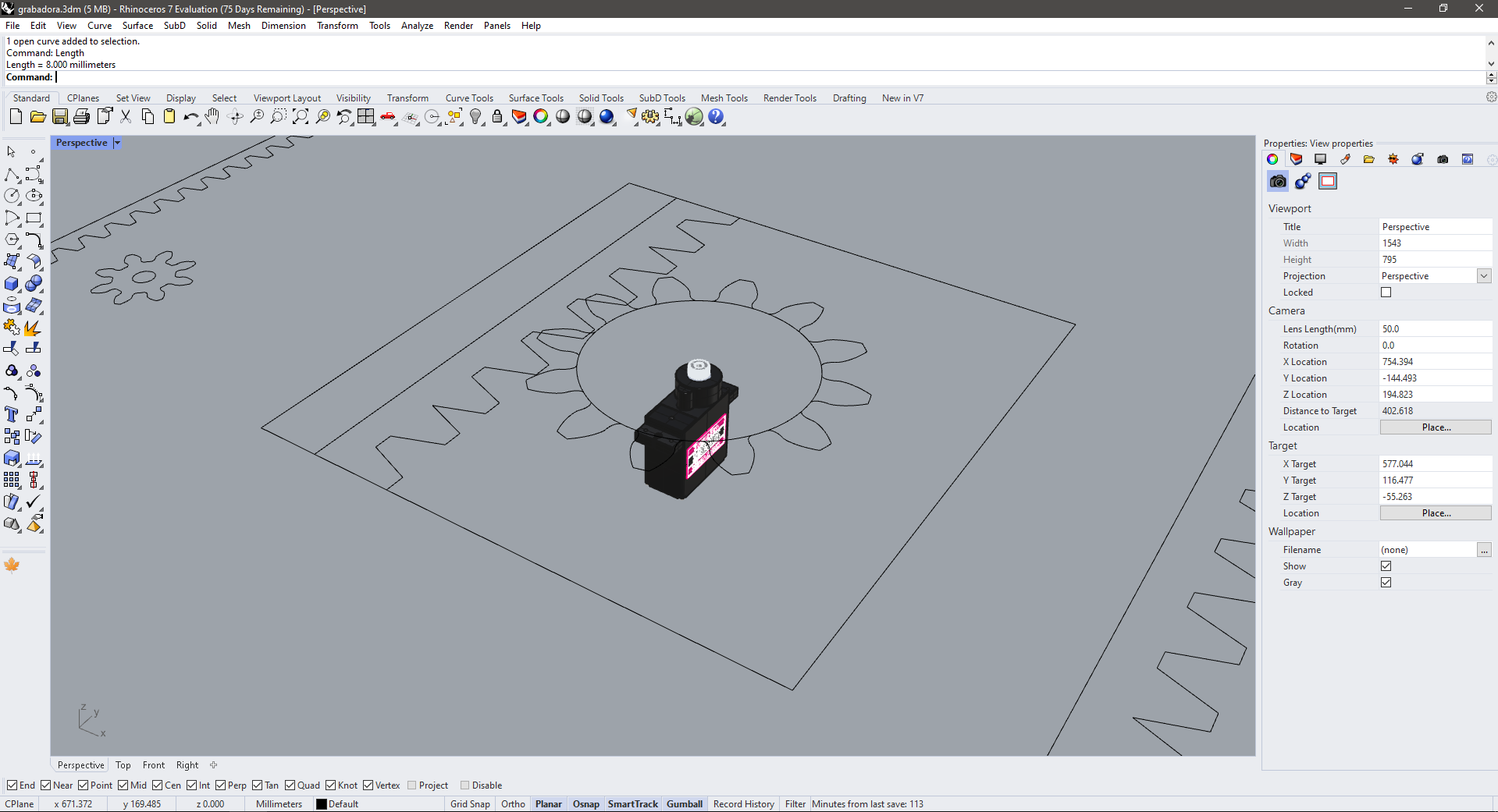
I think that having enough space to fit a square 10cm matrix would be enough to test the prototype, so all the measures of the machine depend on this, also 1010cm is the standard size of a *copper PCB plate, so maybe I could test some engravings in the Modela to simulate a printmaking technique called drypoint printing.
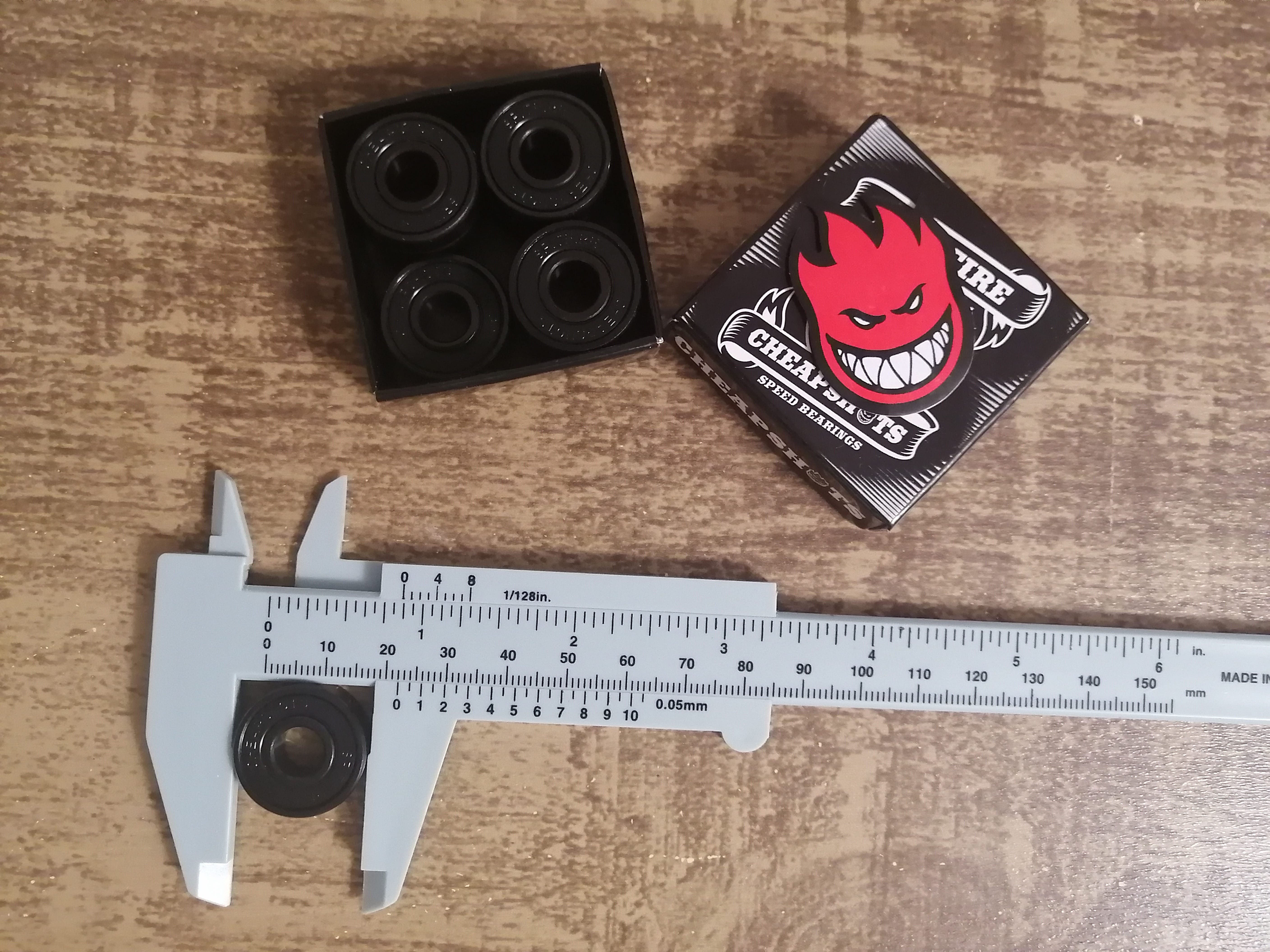
I have some spare skate bearings from a new board setup I'm working on, so I’ll be using this for the sliding bed mechanism.
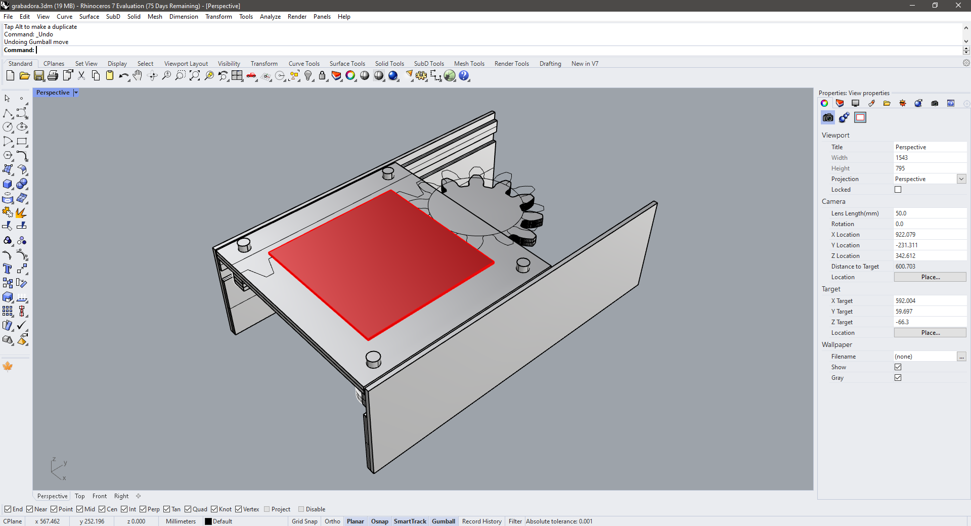
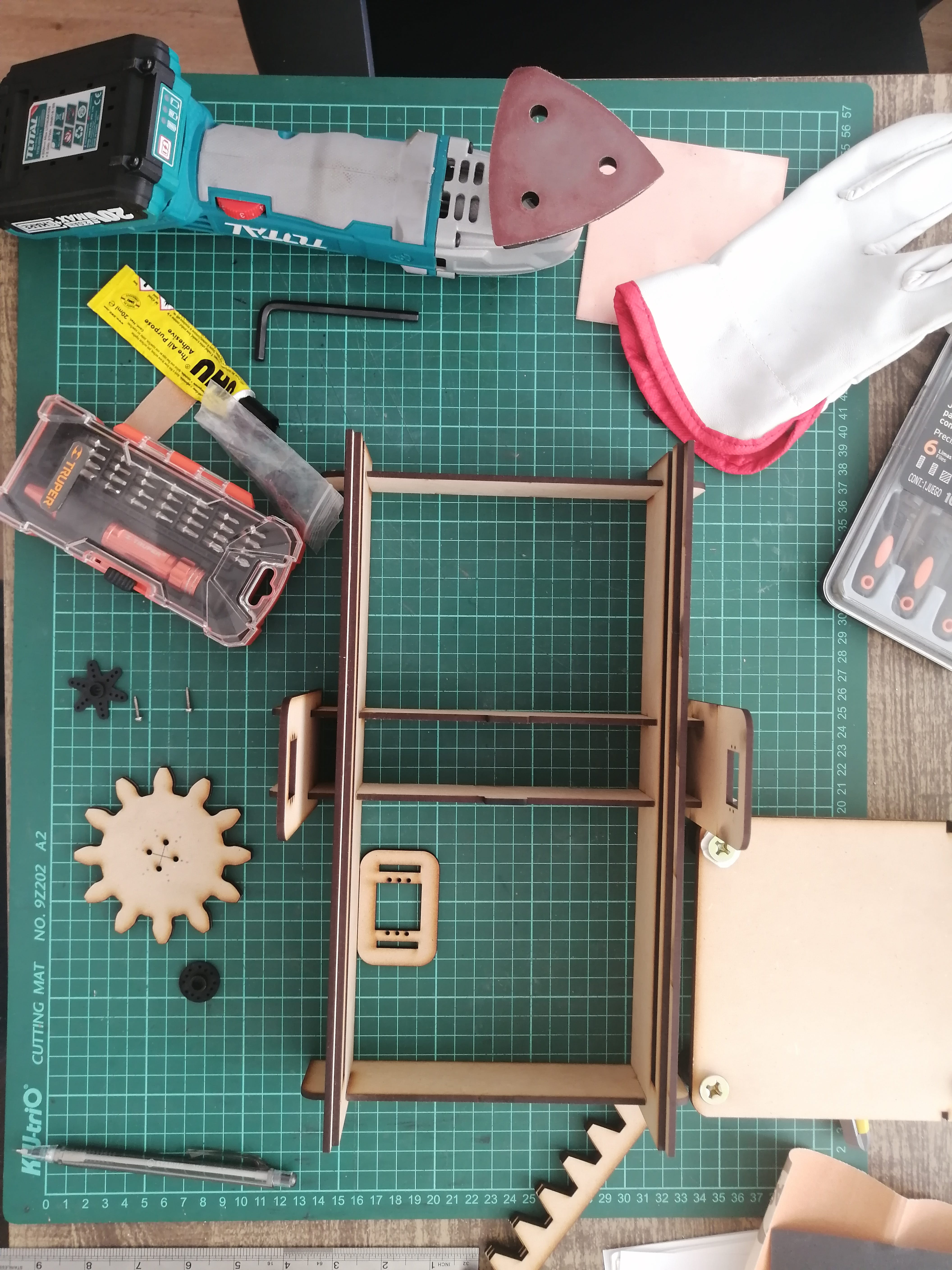
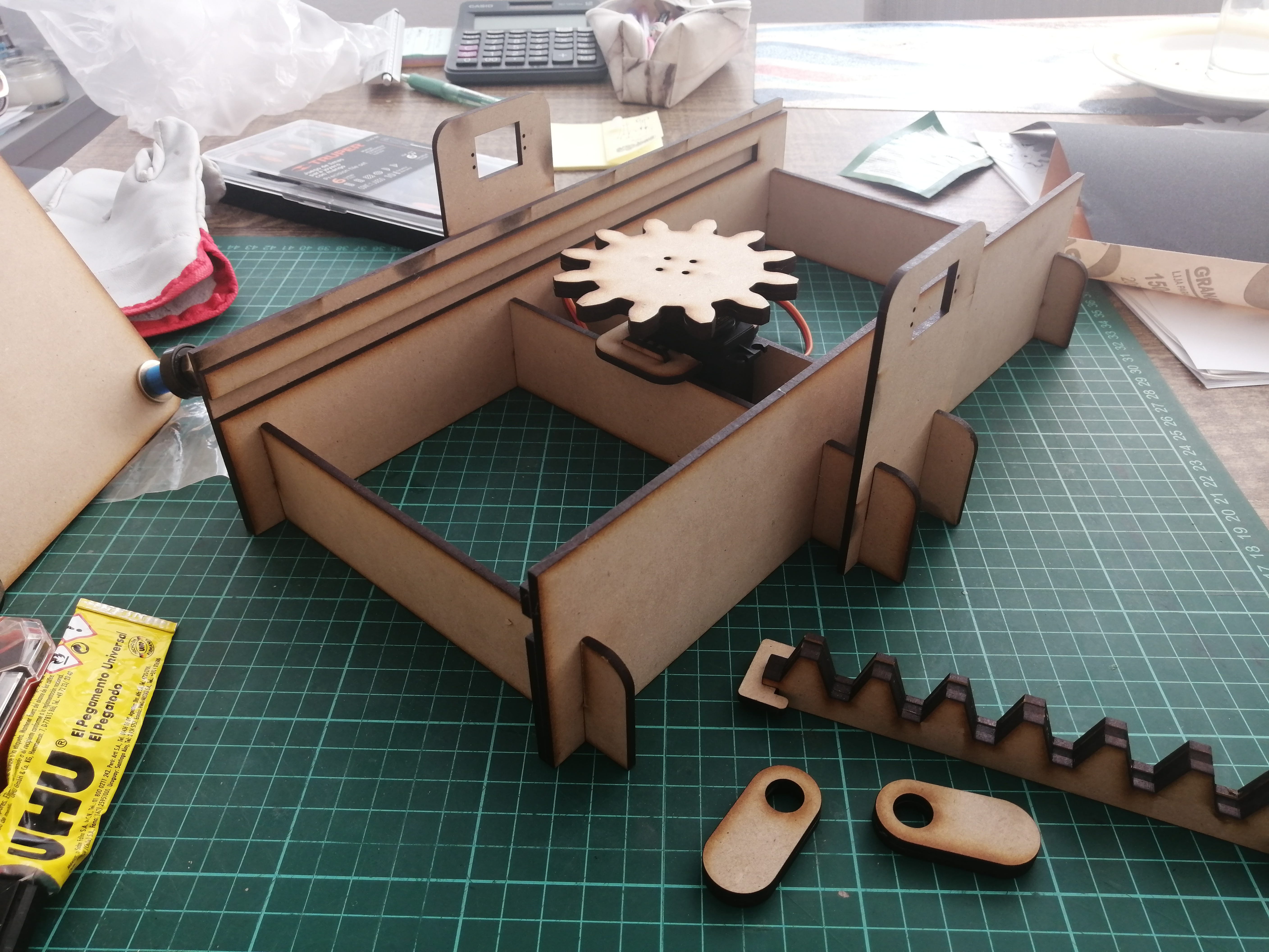
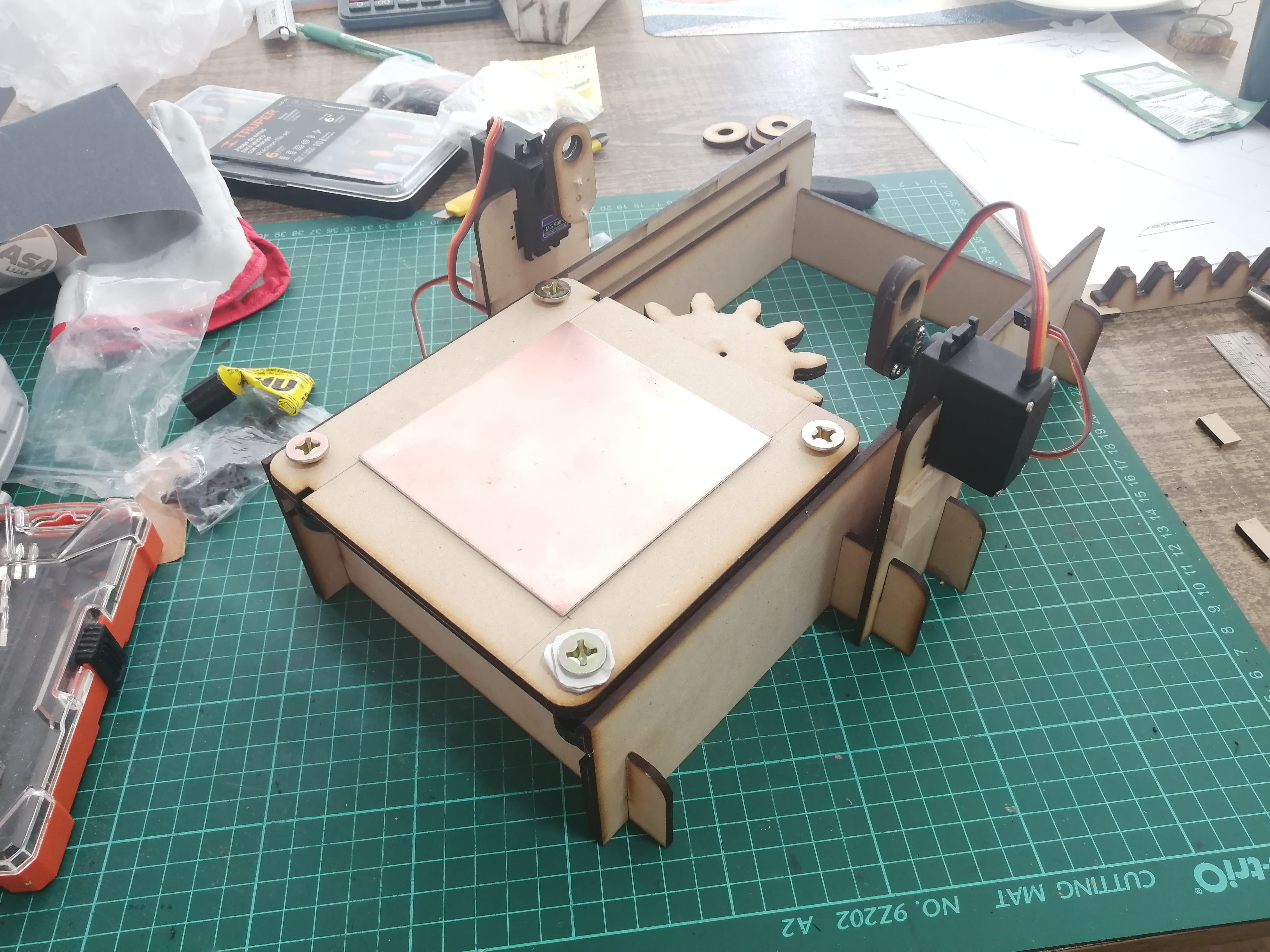
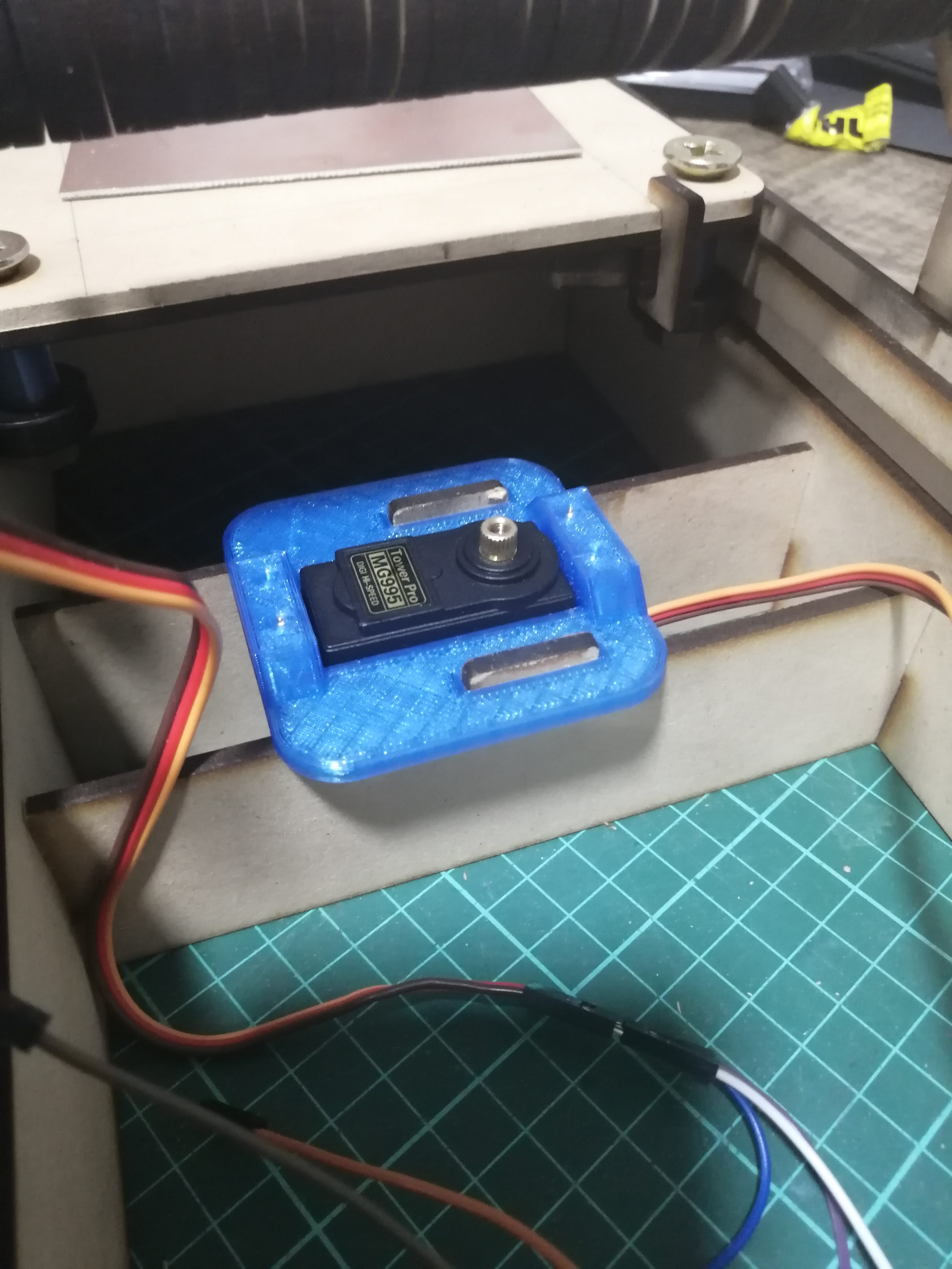
I’ll be making this prototype on 3mm MDF, using a double layer that could make a rail for the bearings. This is how the mechanism will look under the bed with the bearings and the rack and pinion setup in place. The servo is already there between two MDF beams that hold the sides of the press together.
The other mechanism is the roller control that needs to hold the paper onto the matrix, this would be made by placing two servos on the sides and having them make a synchronized bascule movement, having the axis of rotation on the servos gears and the roller in the other side.
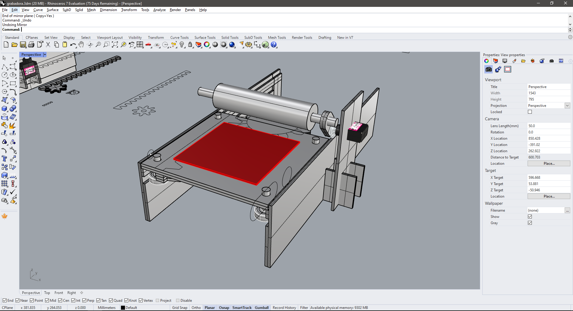
The roller needs to move freely for the matrix and paper to slide under but at the same time making enough pressure to set the ink.
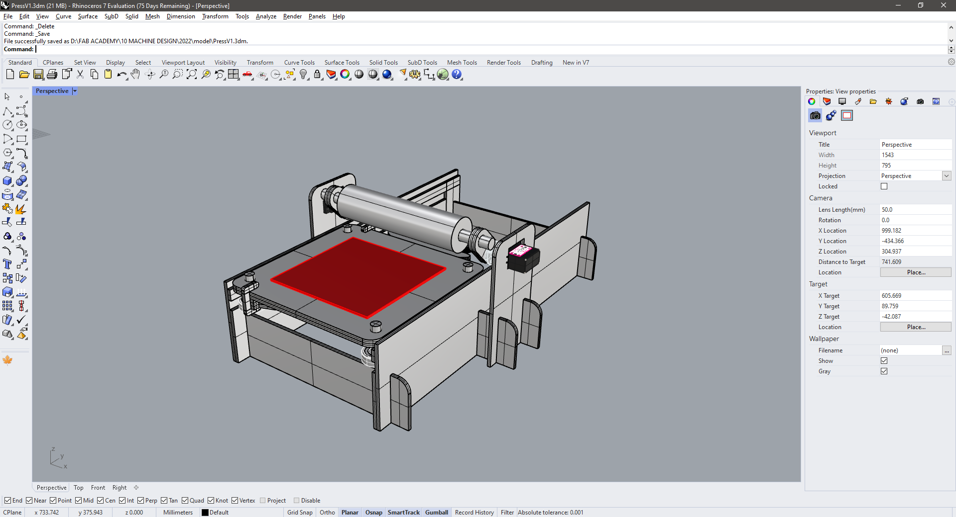
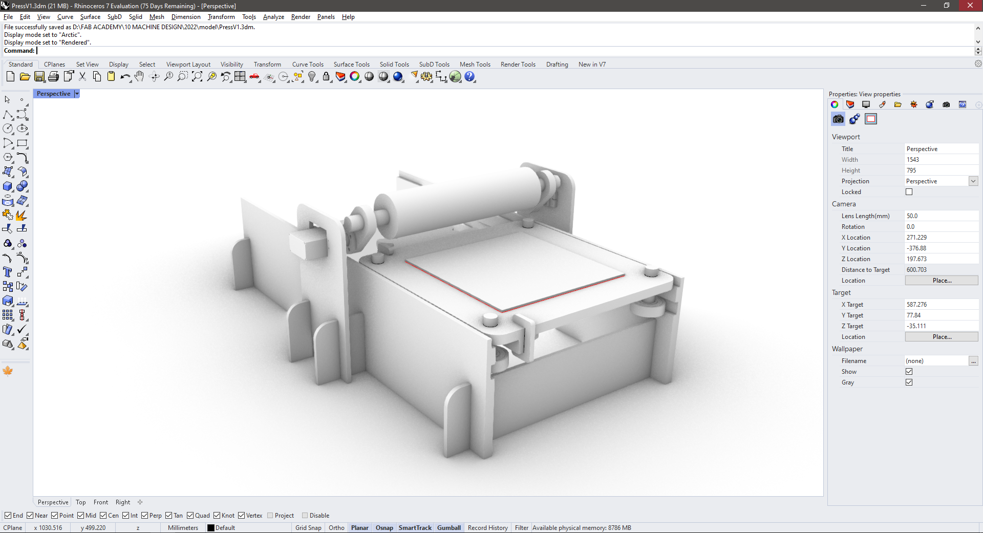
This is the final machine design.
Fabricating the prototype
The prototype is made by laser cutting, trying to have the least parts possible, however, due to the holidays, FabLab ESAN was closed so I had to hire a laser-cutting service to make it on time.
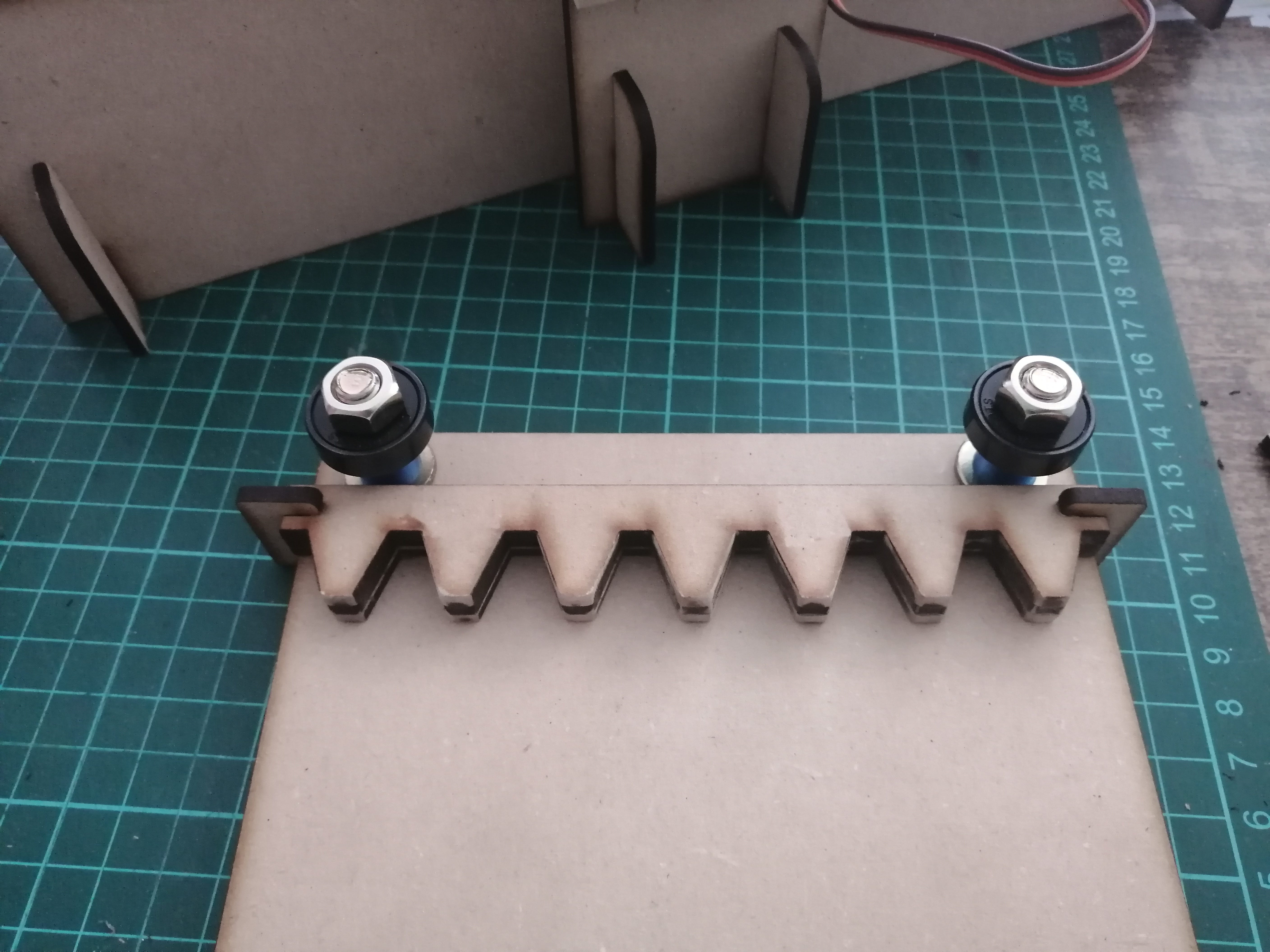
The first part to be assembled is the bed and the bearings to test that it slides as it should, and it does! I’ve used some spare nuts as spacers, but I'll be printing some spacers later.
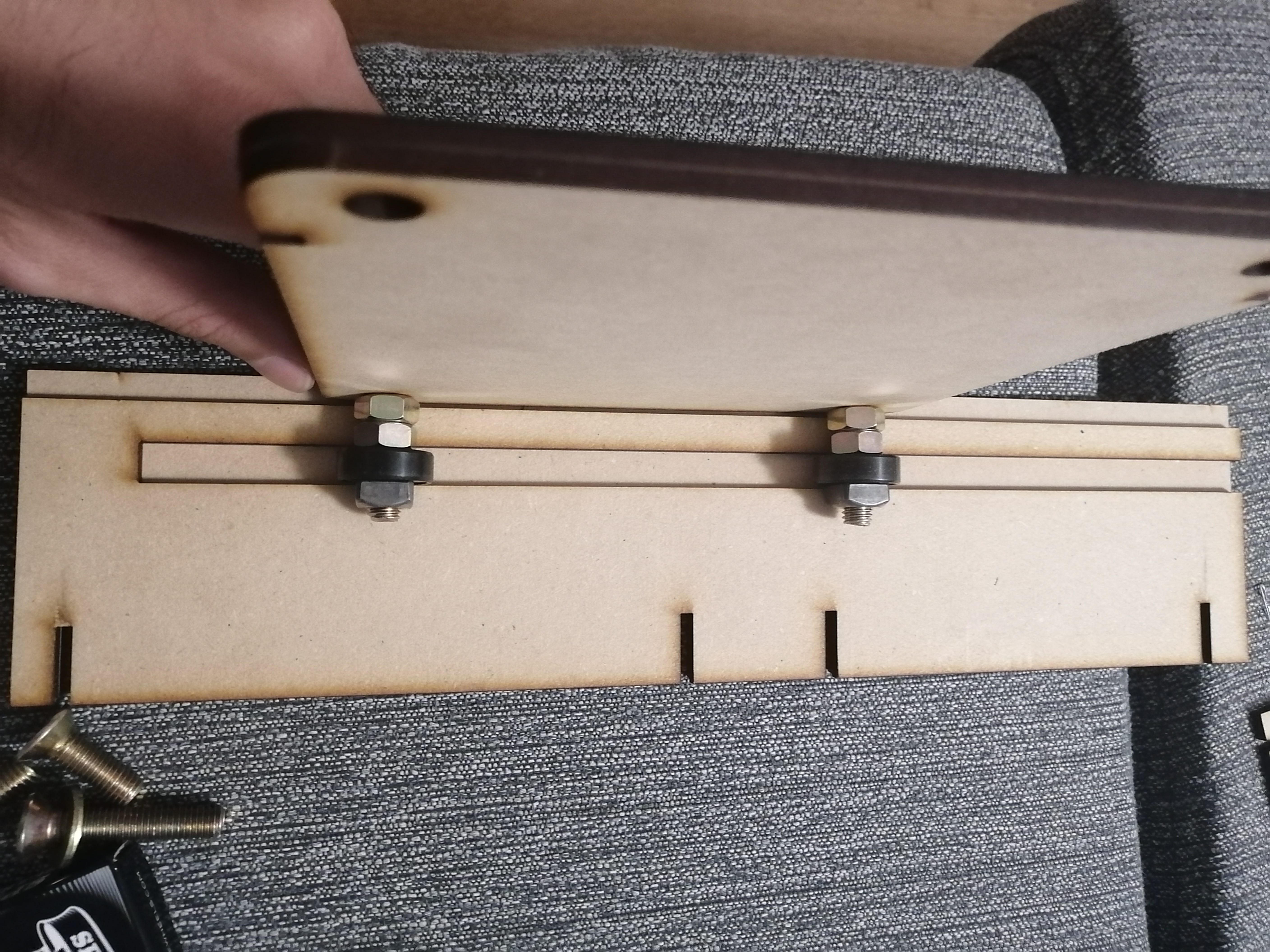
This is the bed (upsidedown) with bearings and spacers in place by M8 bolts and nuts.
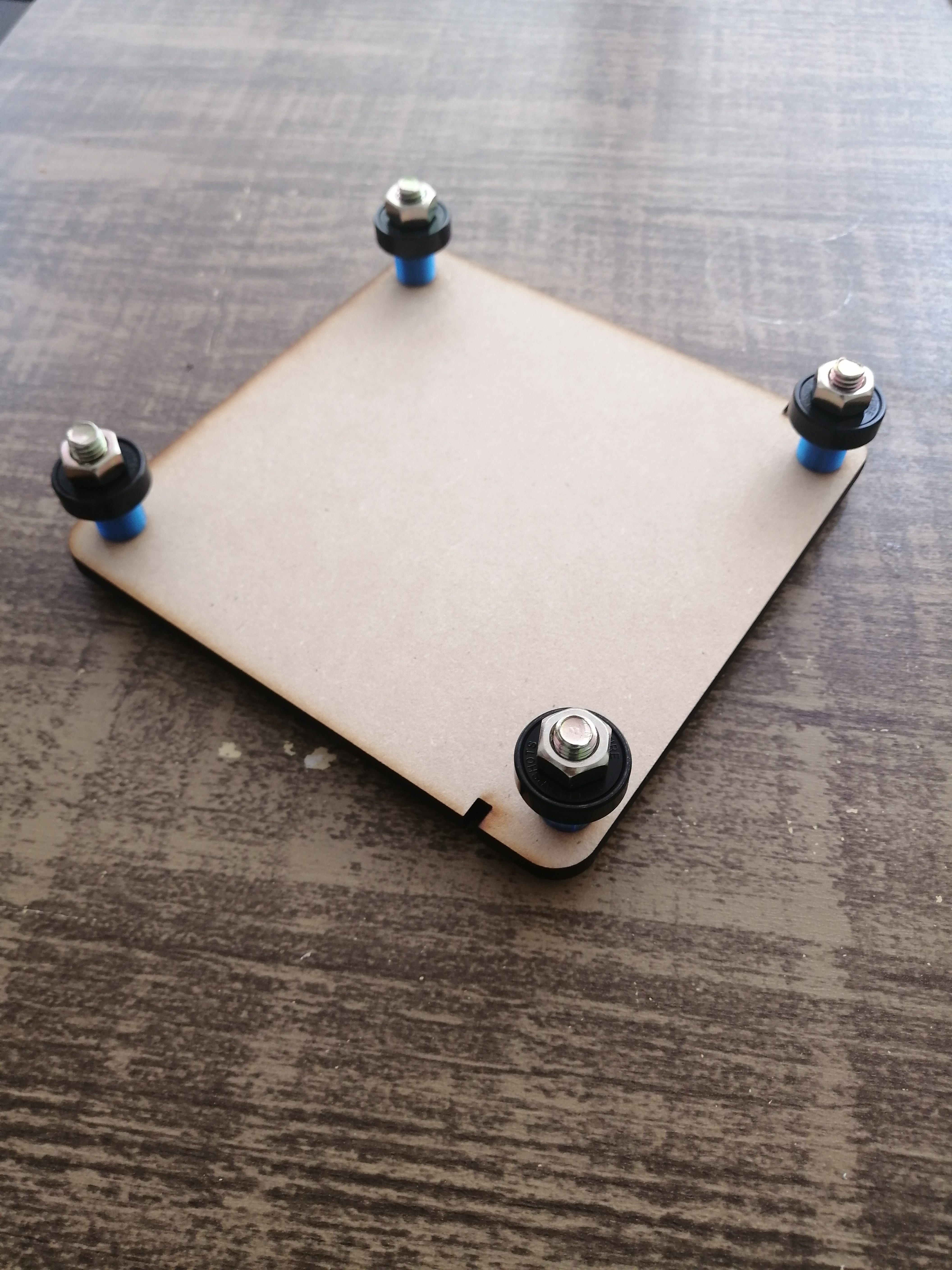
The bed is also designed to be removable and to be mounted with easy-to-change matrices.
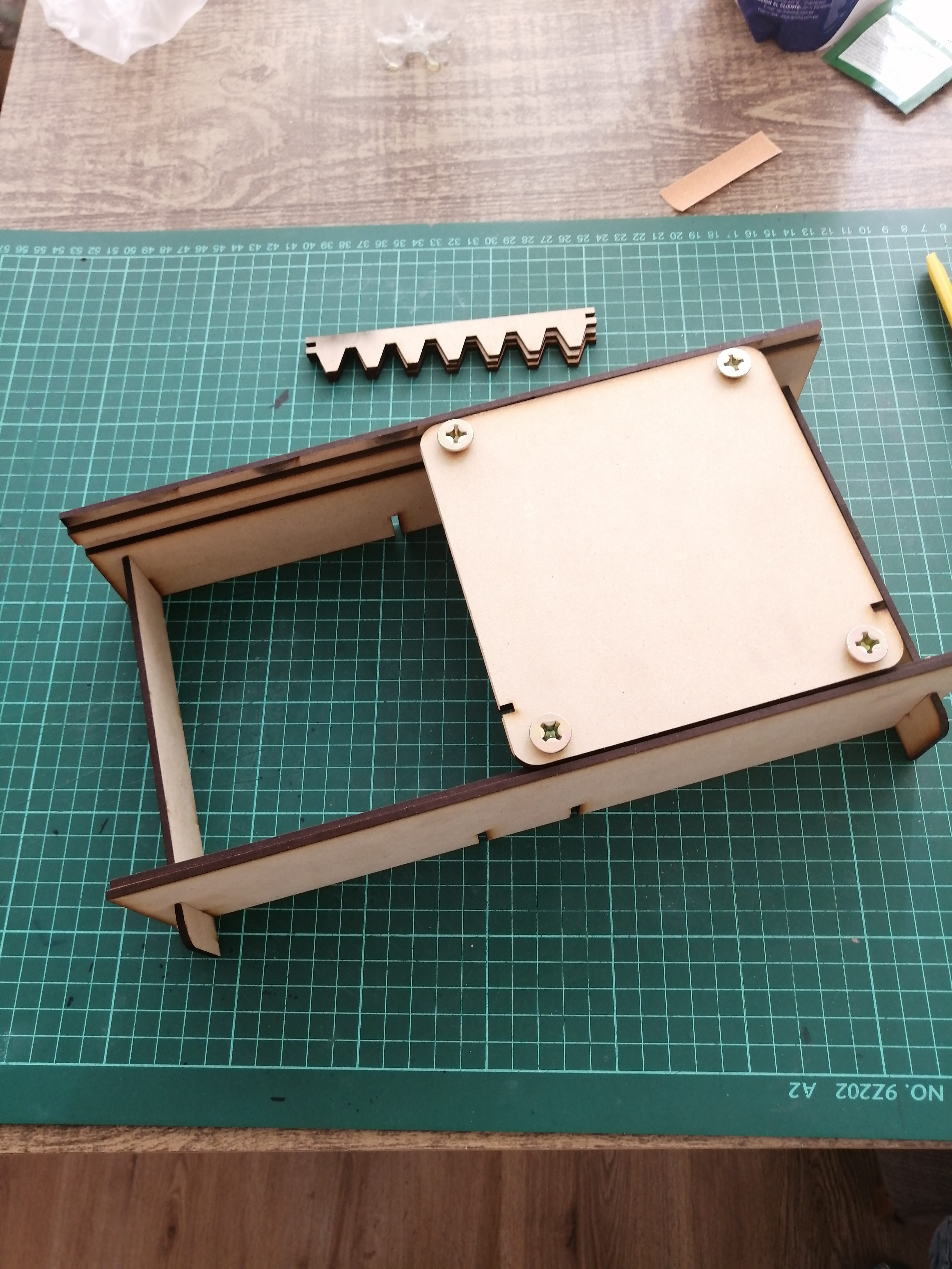
A light sanding was needed because the MDF had a 3,2mm thickness, so this made the press-fit design a little too tight on the double layer side pieces.
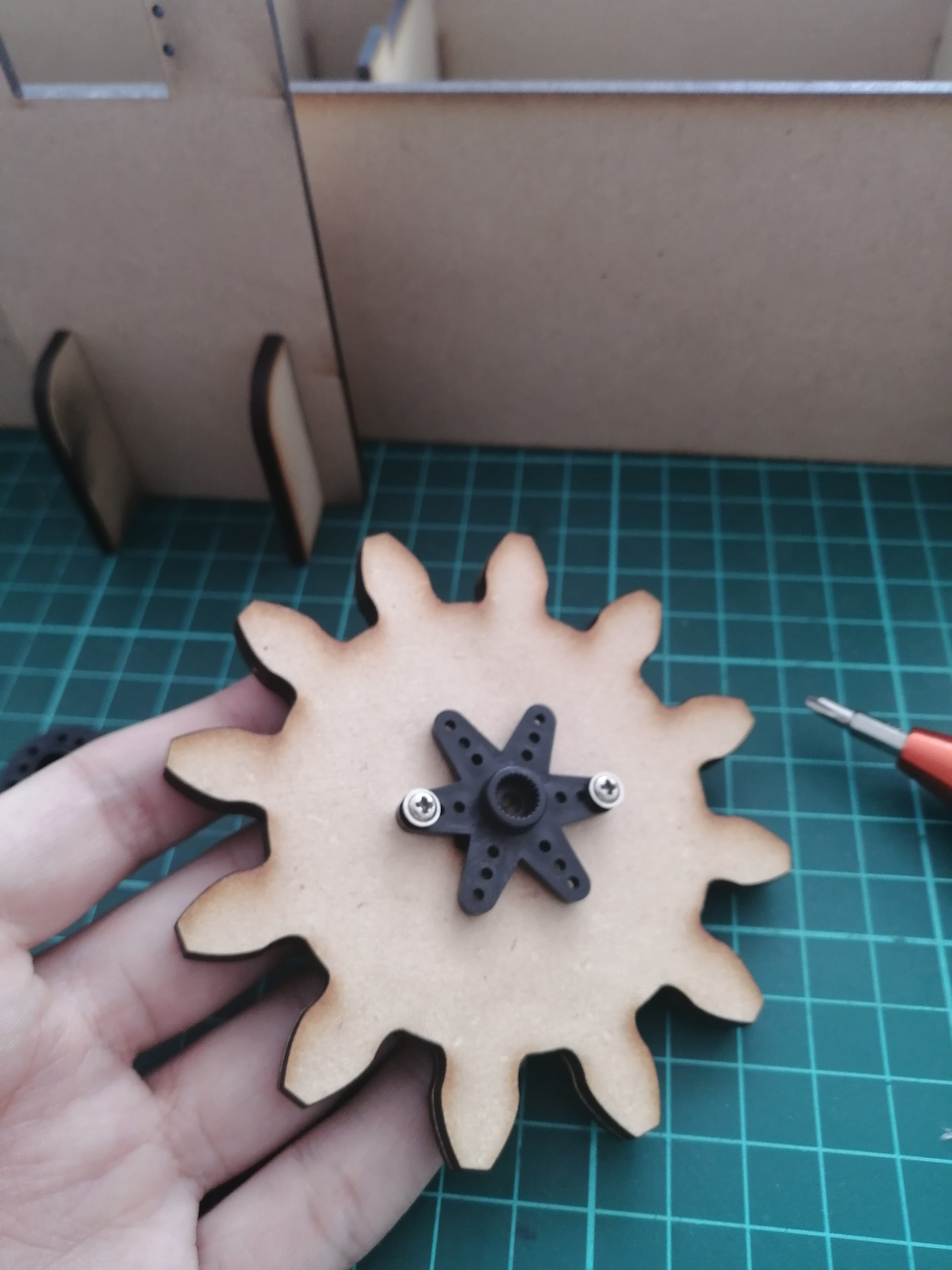
The main gear fits correctly, so I’ve mounted a servo attachment in the center. Luckily I made some laser cur holes in the design to work as guides.
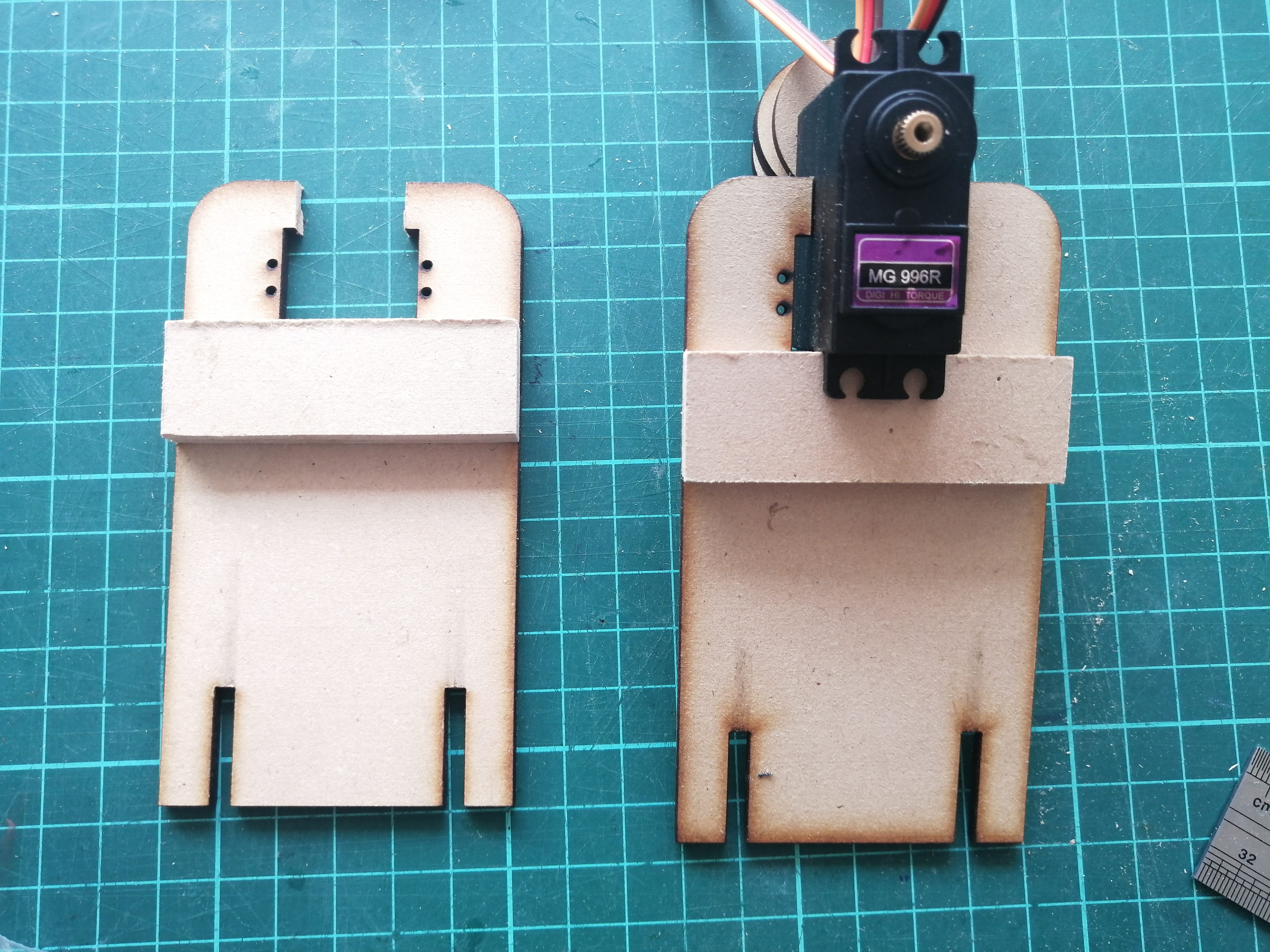
The servos are bigger than originally planned, so at least the power won't be an issue, but this needs extra work on the fitting of the pieces, I’ve already designed with smaller servos in mind considering side adjustments.
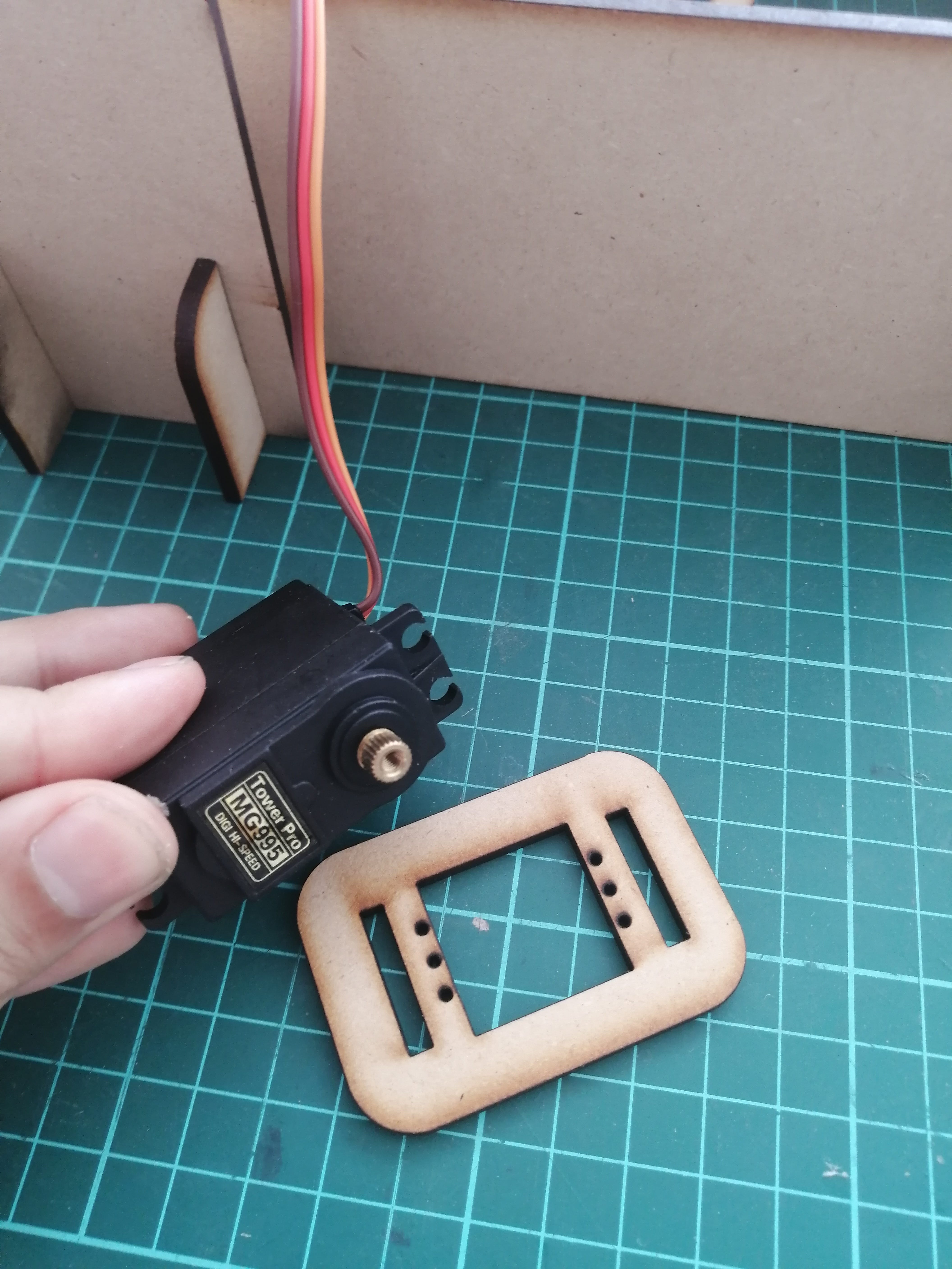
Made some modifications with a cutter knife to hold the bigger servos, and that should be enough for the movement test.
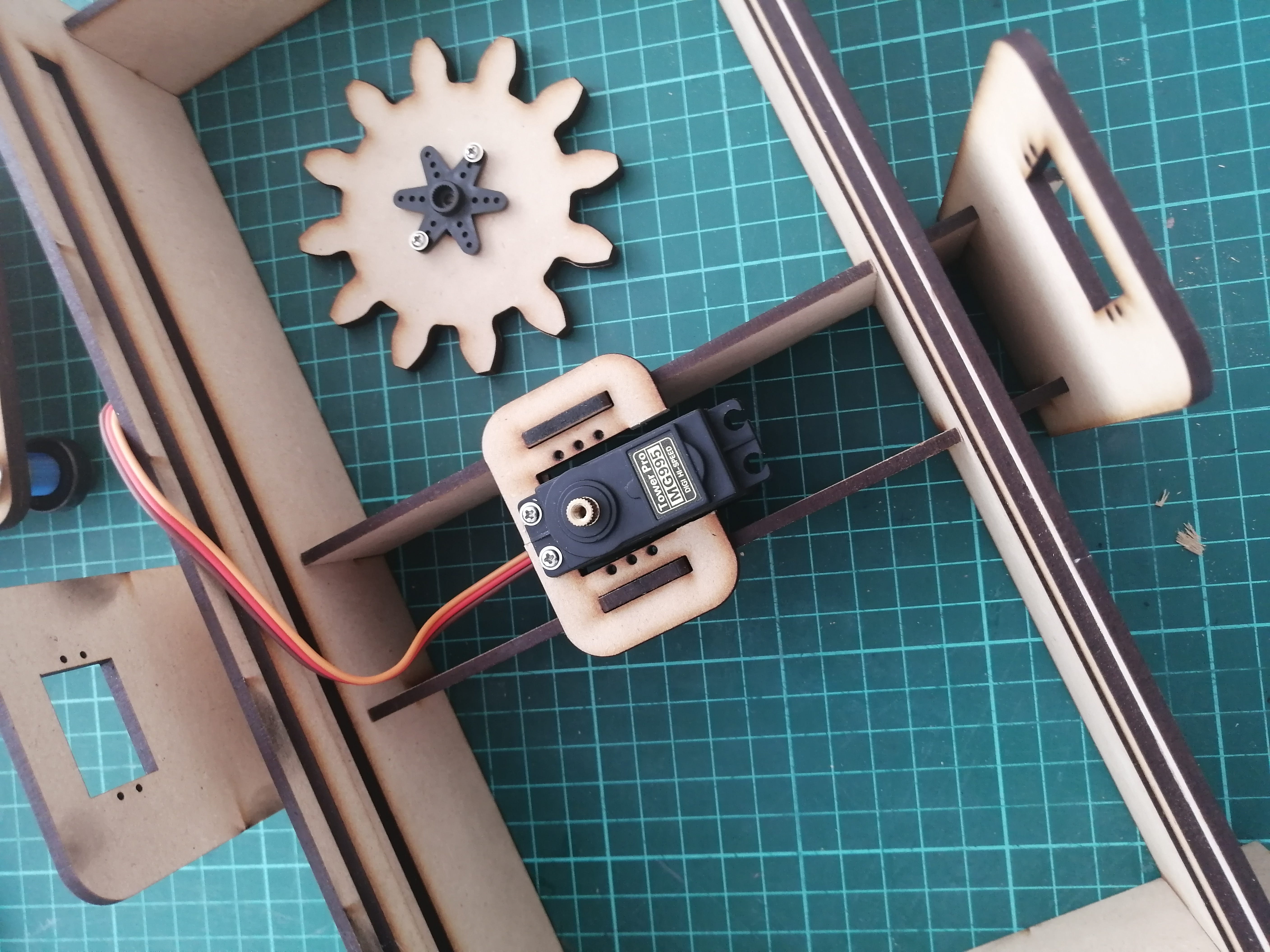
Somehow the rack piece was not aligning as it should, to be precise, the gear teeth are not aligned. This was probably caused by not placing the MDF flat on the laser cutter bed. Anyways, I’ll do some tests without gluing them together and directly attaching the rack to the bed by some brackets.

The rack has enough clearance for the bearing but it's thick to compensate for the alignment on the pinion.
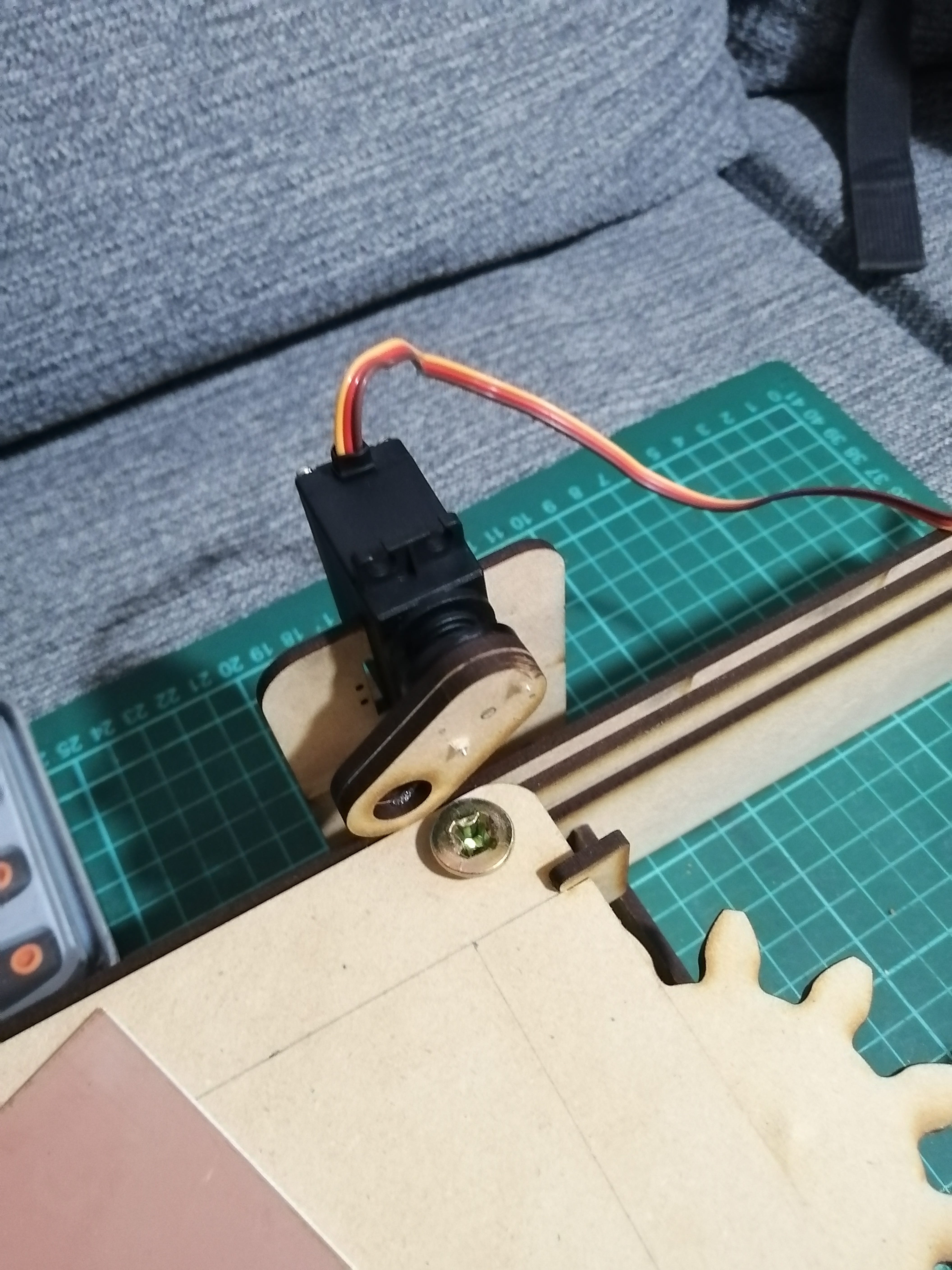
The pieces that hold the two servos on the sides for the roller movement have been modified too, by a temporary press-fit.
The bascule pieces are held together by screws to the servo attachments in the same way as the main gear. These pieces only need to move 90° degrees to hold the matrix and paper together and could be set to a correct angle by moving the pieces by hand.
The servos on the side will move in opposite directions to move the roller down. This will be made by having a 90° angle as a reference by having the pieces pointing up, next, one of the servos will move to a 0° degree position while the other will move to a 180° position.
I’m using a 10mm wood rod to form the roller axis, I previously designed and cut a lot of MDF circles to form the roller, and the original idea is to have them glued together and wrapped in a soft material to cushion the paper.
There are two options: for the circles to move freely on the wood rod, or for the wood rod to move freely on the bascule pieces of the servos. I ended up using the first option.
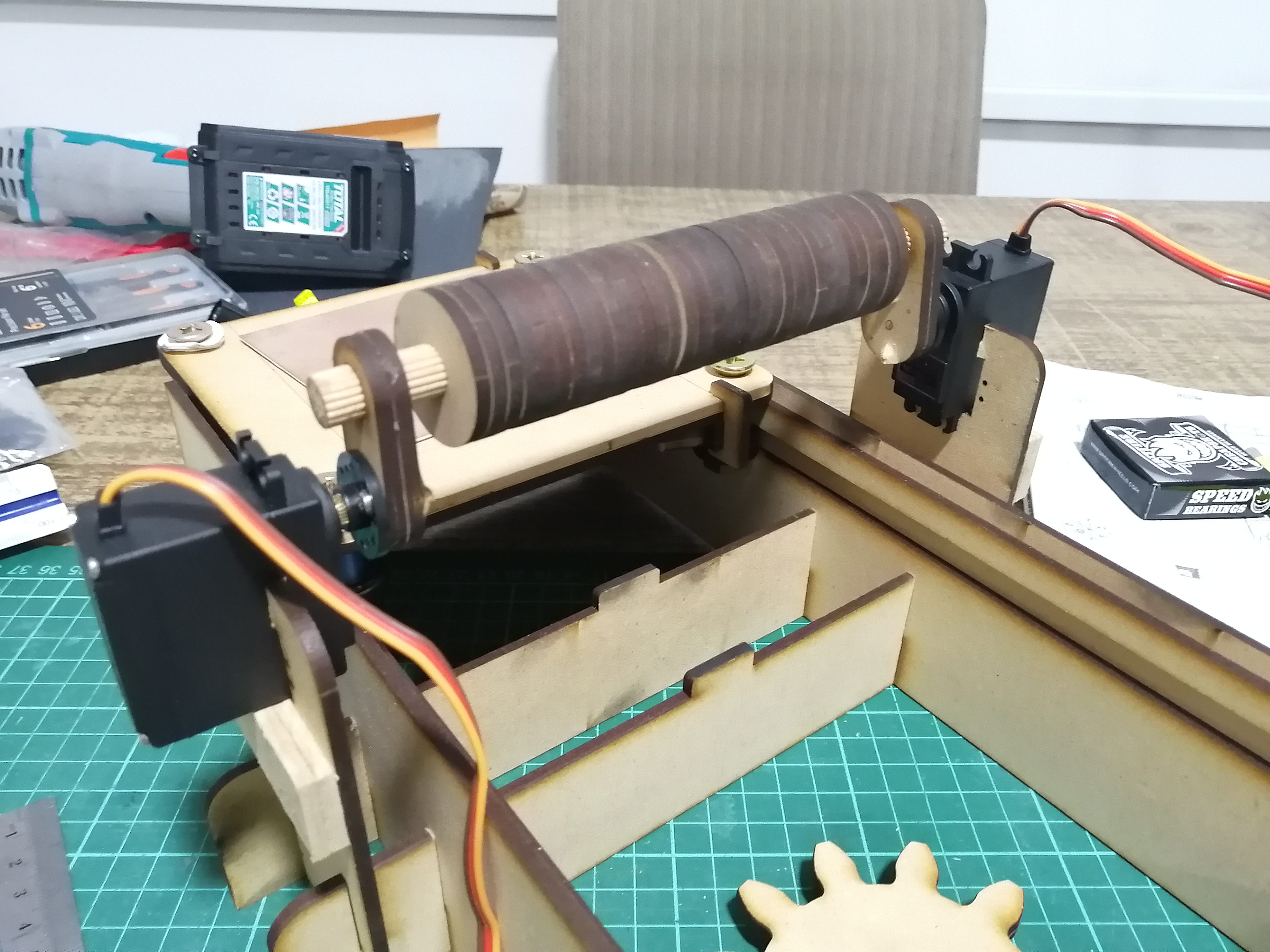
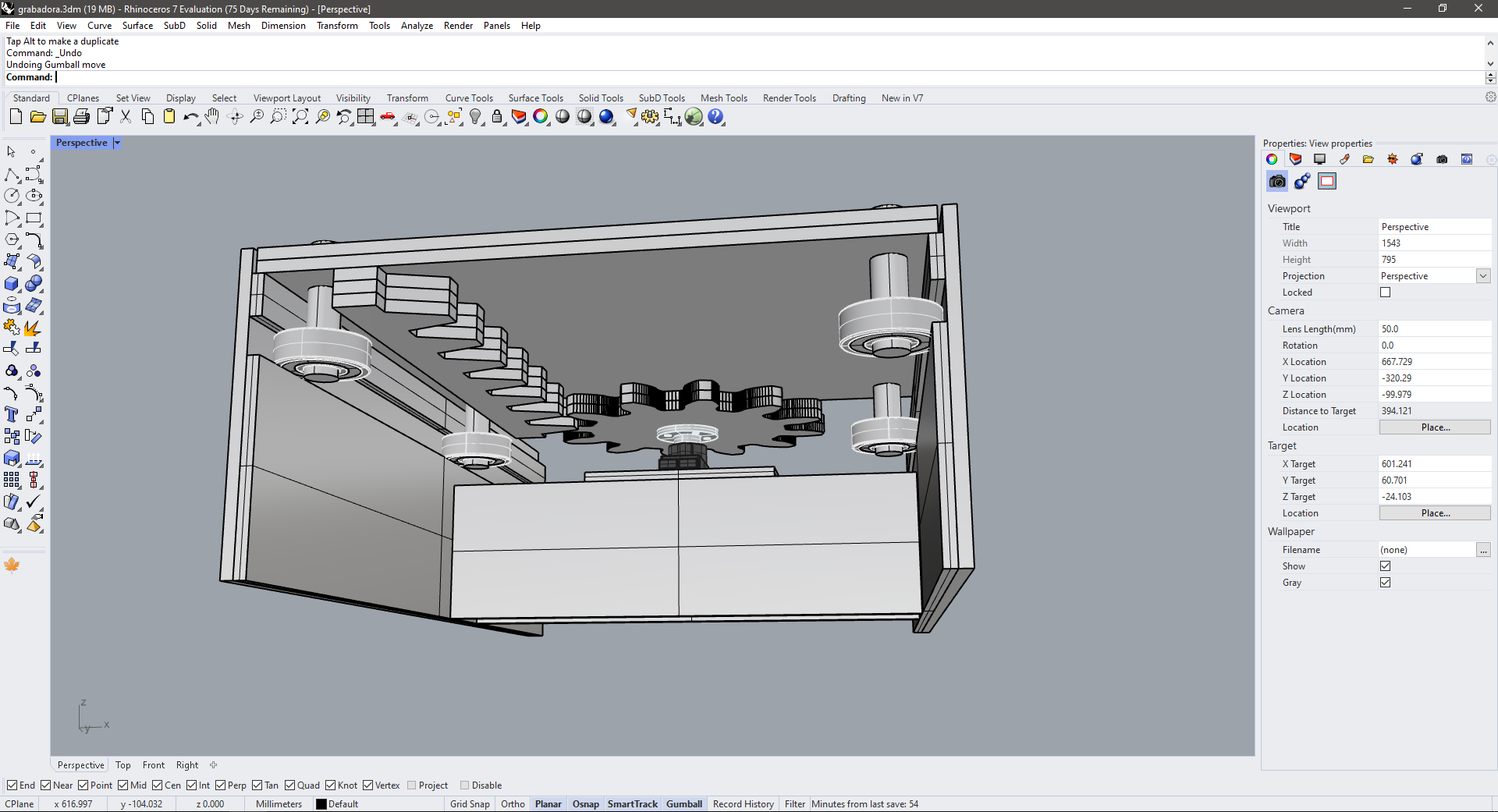
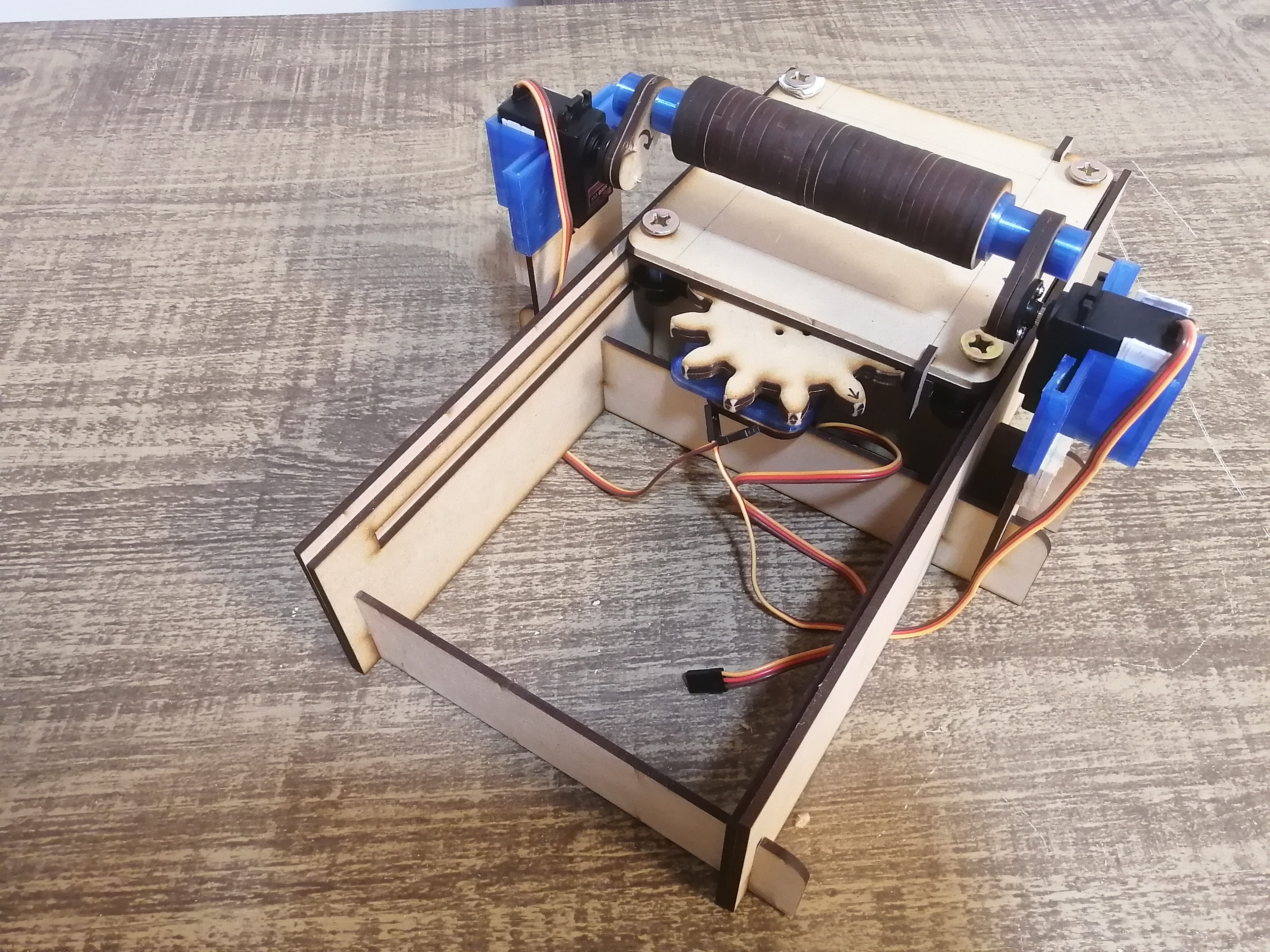
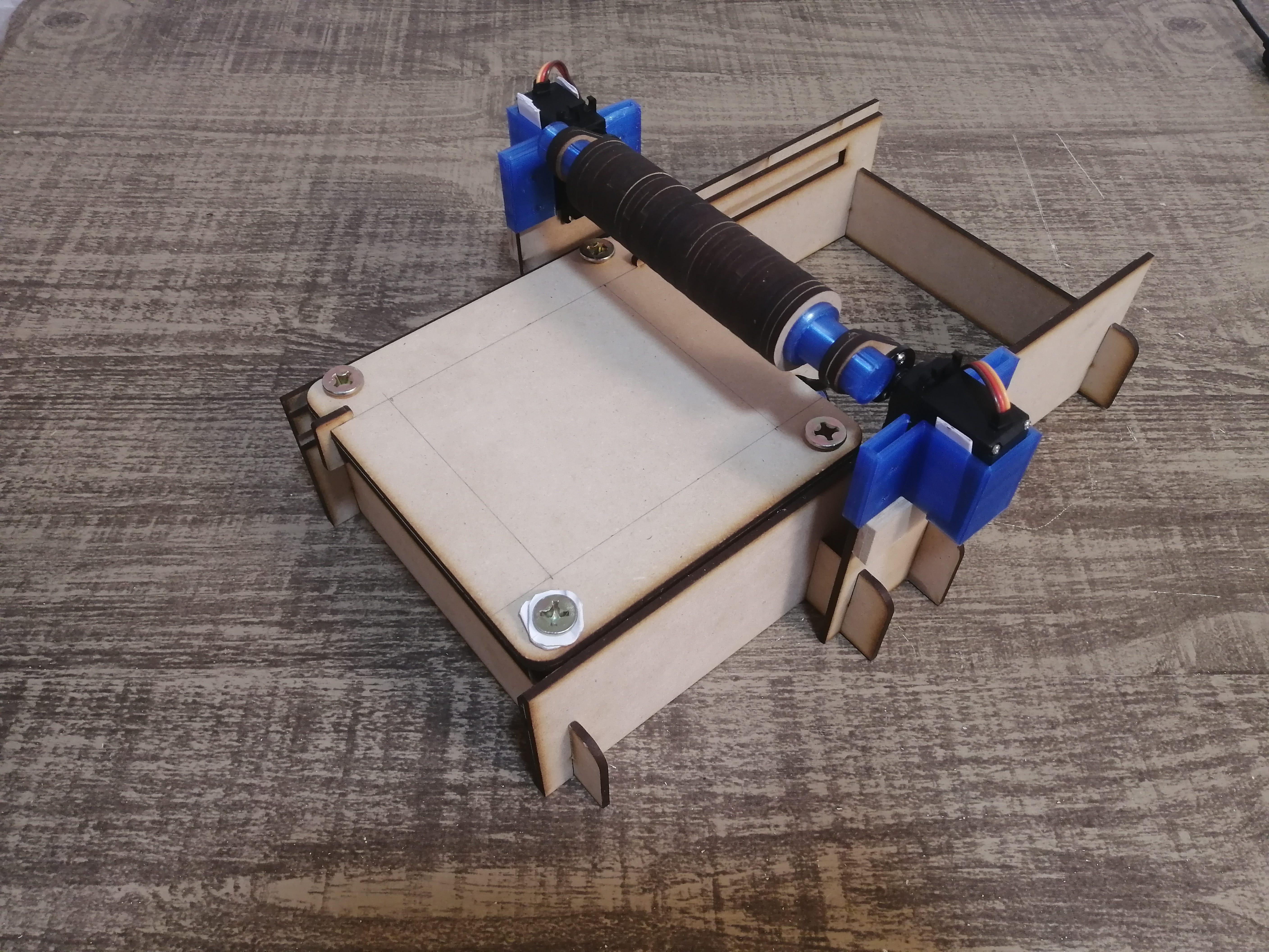
This is the final assembly, and everything moves as it should, at least by hand for now. Only a couple more parts would be 3D printed to fit better the servos and some other parts.
New 3D printed pieces for the main gear servo. notice that still uses the laser cut notches on the MDF structure.
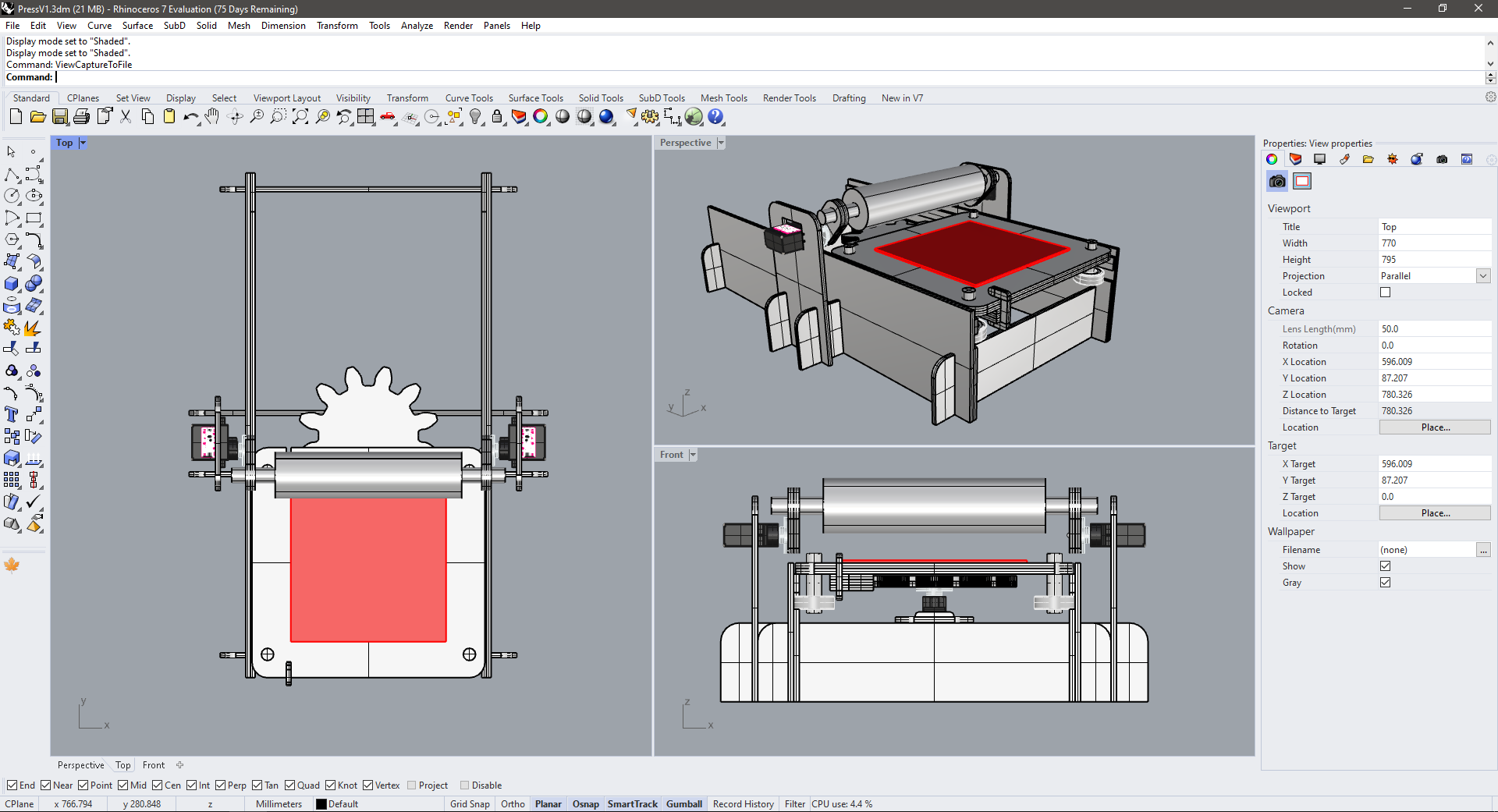
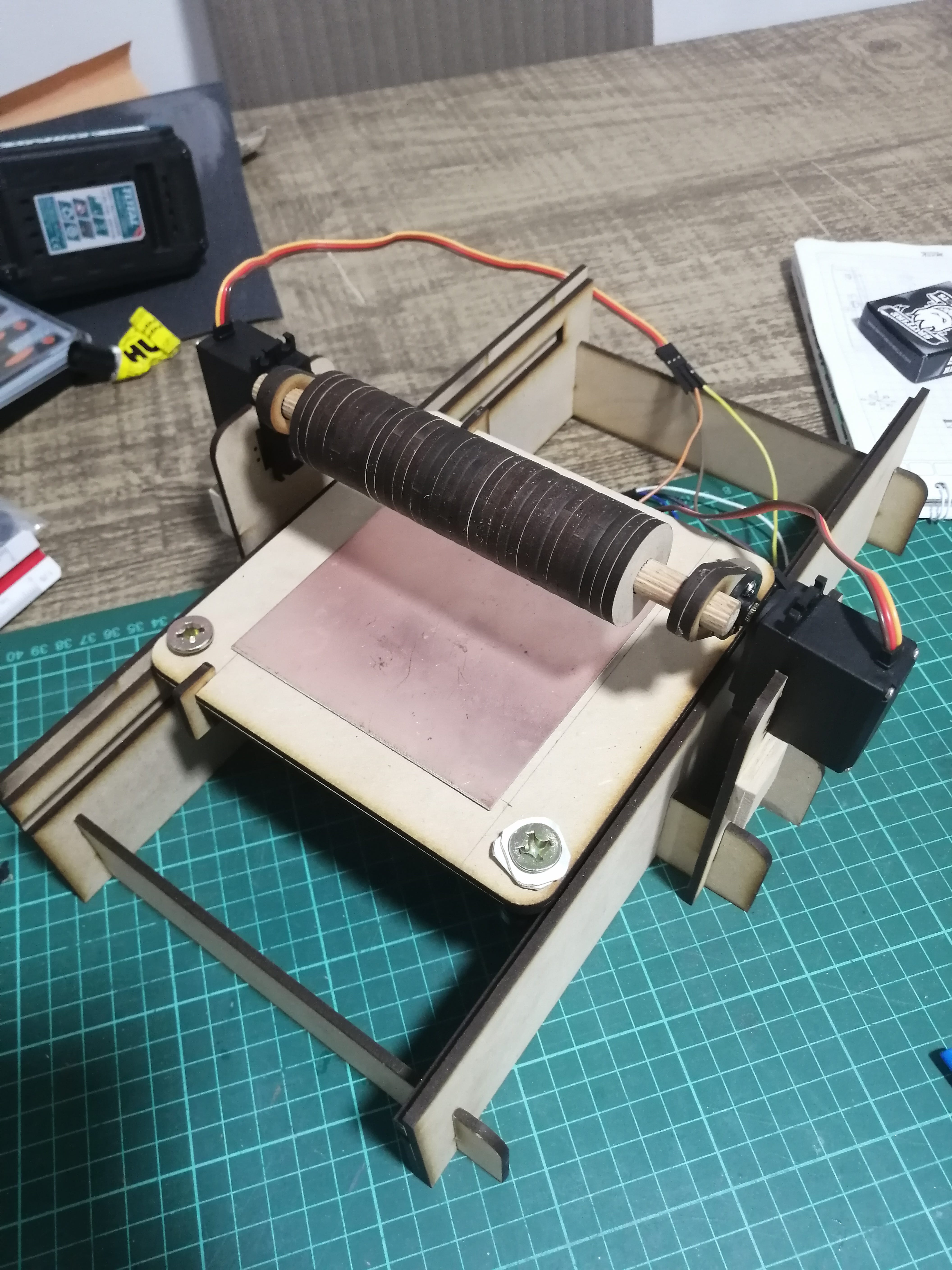
Some final shots from the back
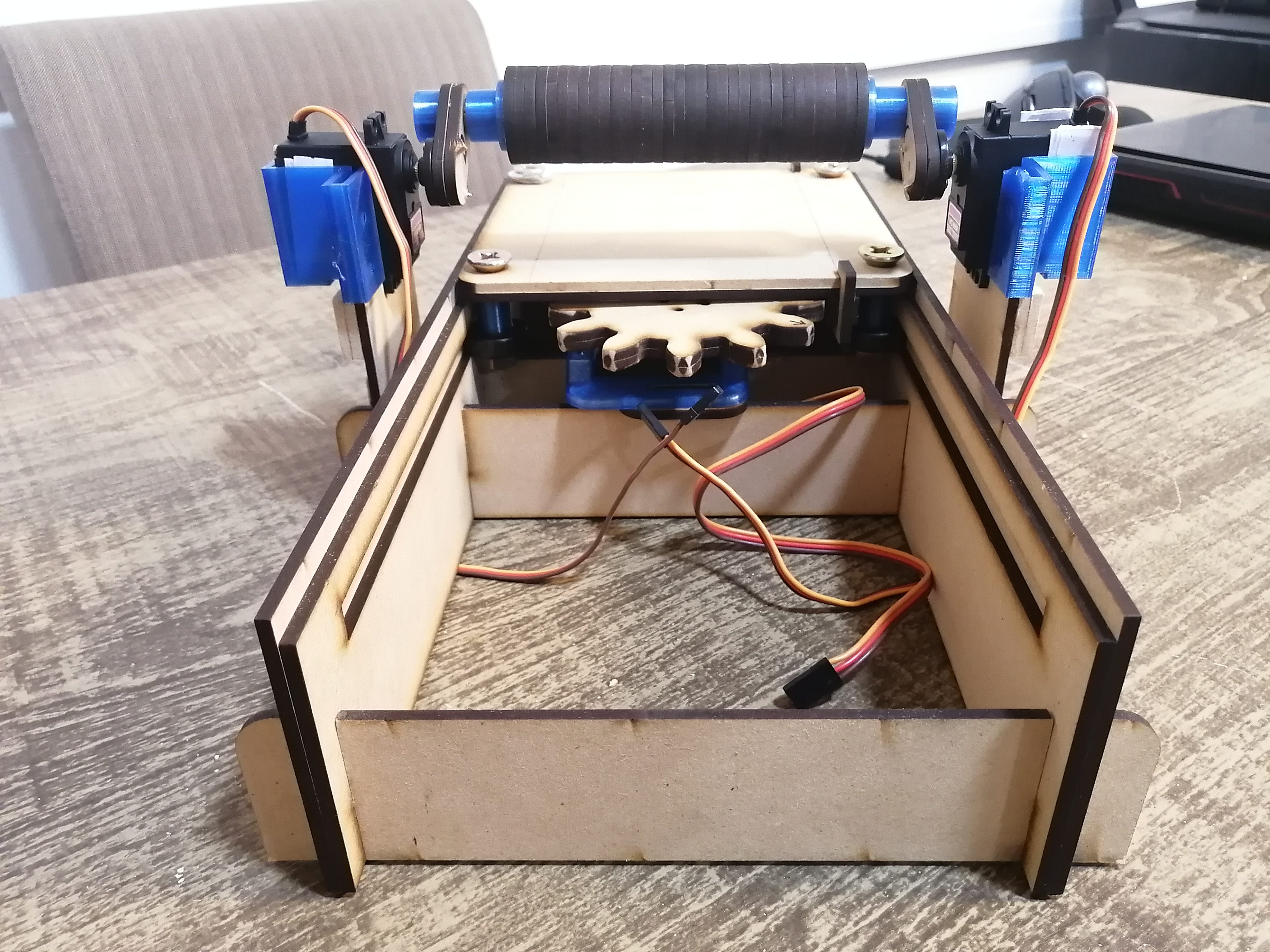
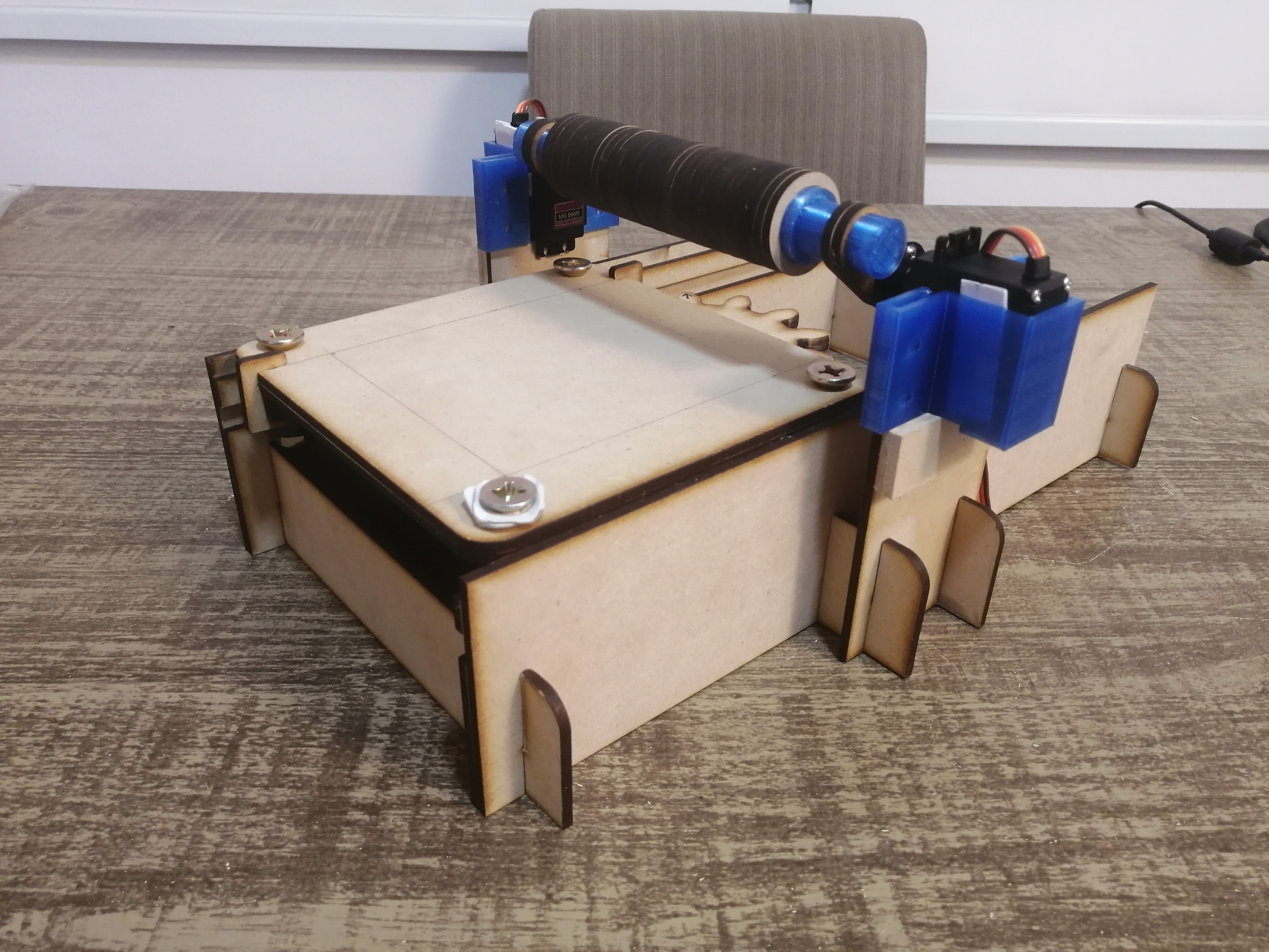
Front views
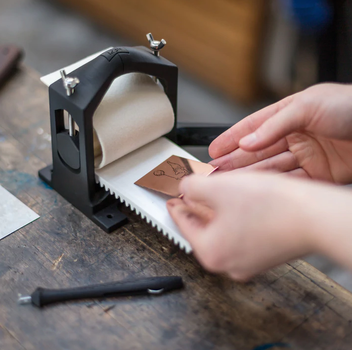
3D Printed matrices
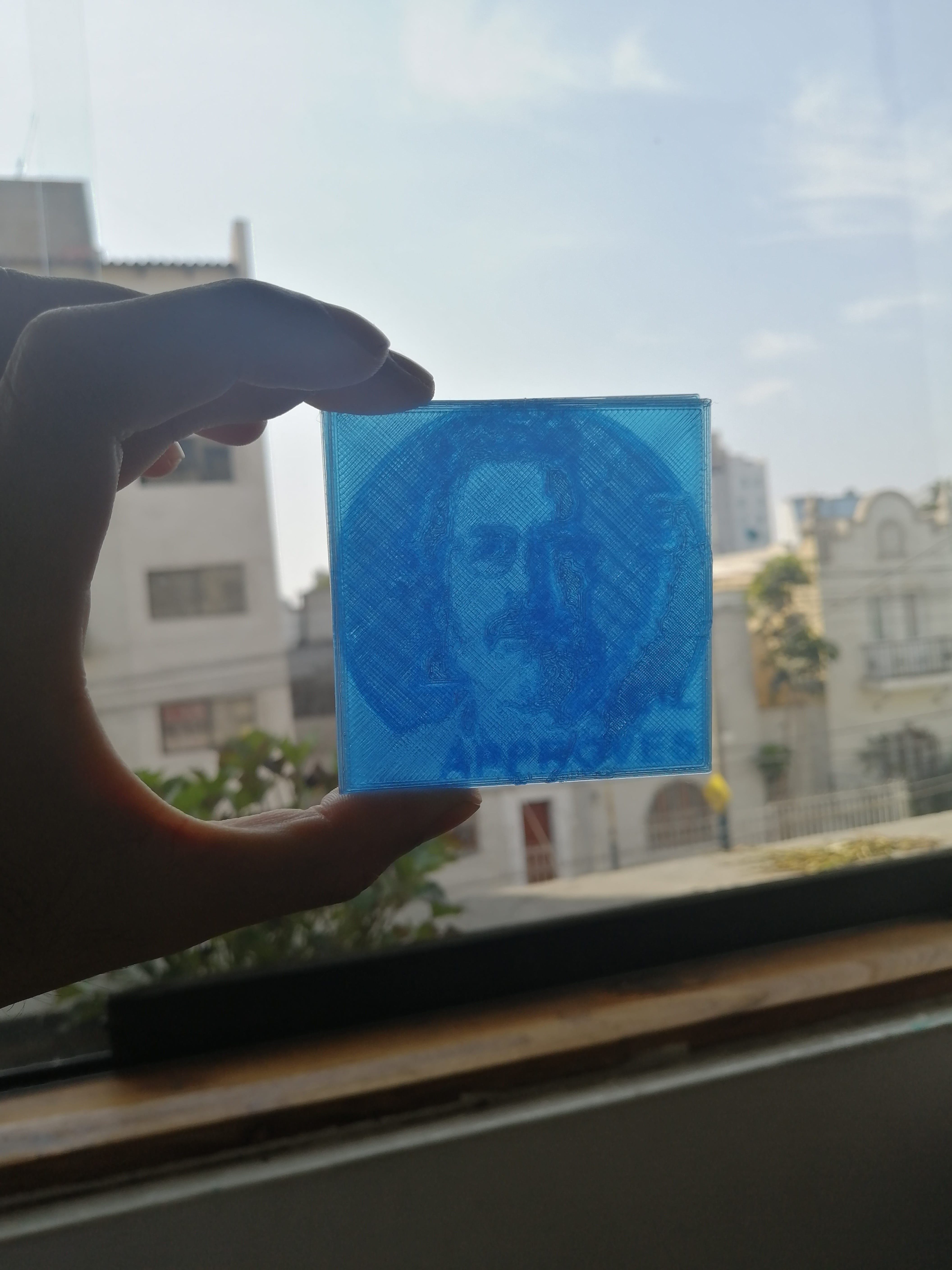
I originally intended to make some drypoint matrices on the Modela, but I don't have lab access yet, so I’ll try with 3D printed ones. The idea is to have a printed relief for the paper to press into. I choose Neil’s iconic photo to make a two-color print relief using black and grey. After a couple of minutes in Photoshop:
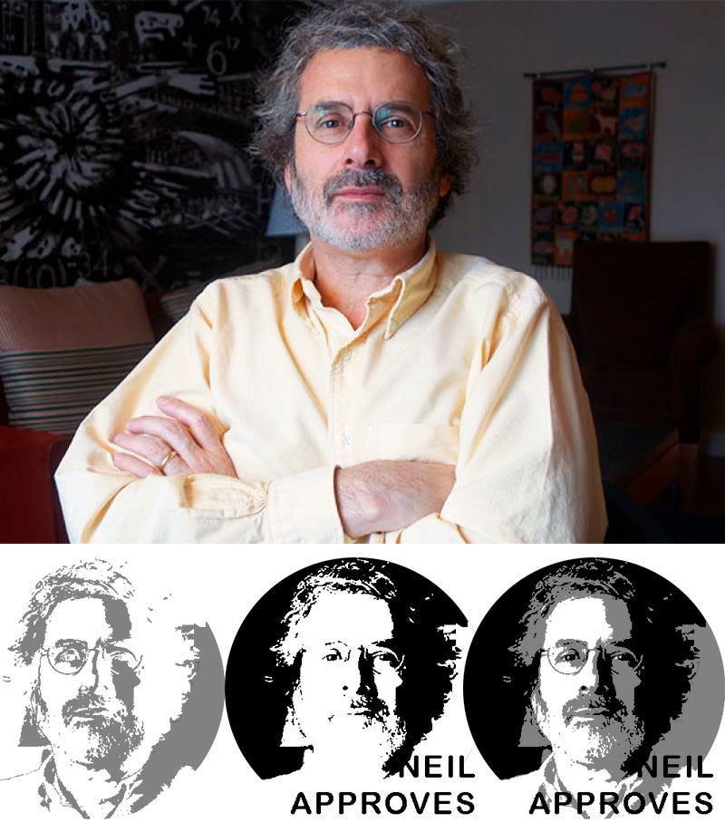
I simply extruded these profiles with an online PNG to STL service as I was having some issues with an expired software… 😰
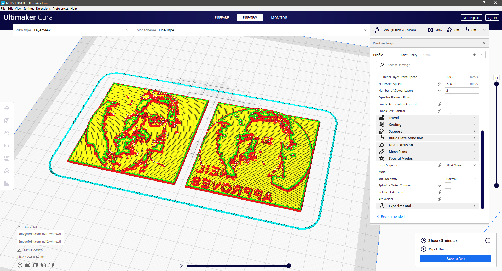
These pieces will need some light sanding to make the 3D printing lines disappear, but we can already see Neil’s face thanks to the translucent filament. Does Neil approve?
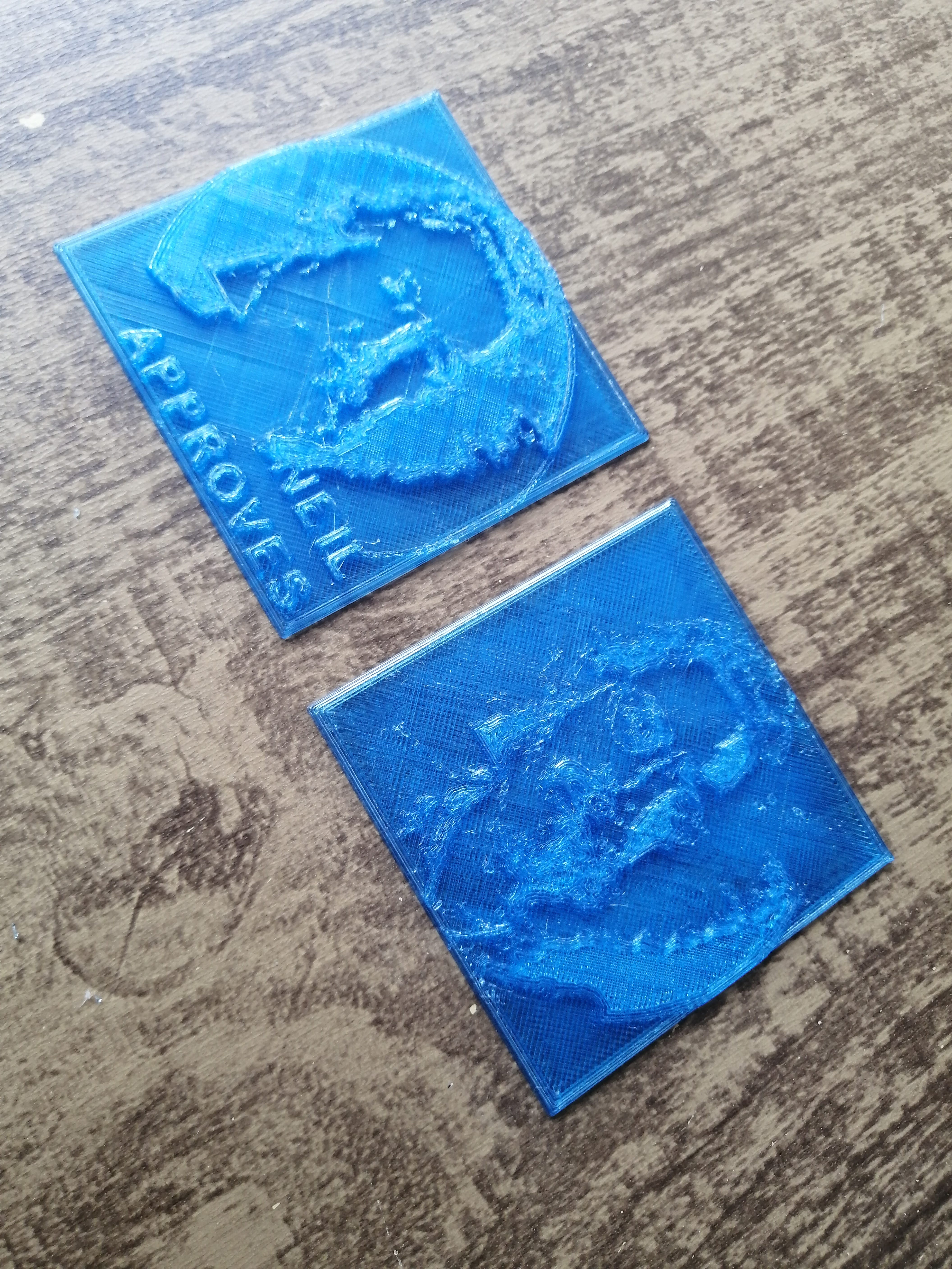
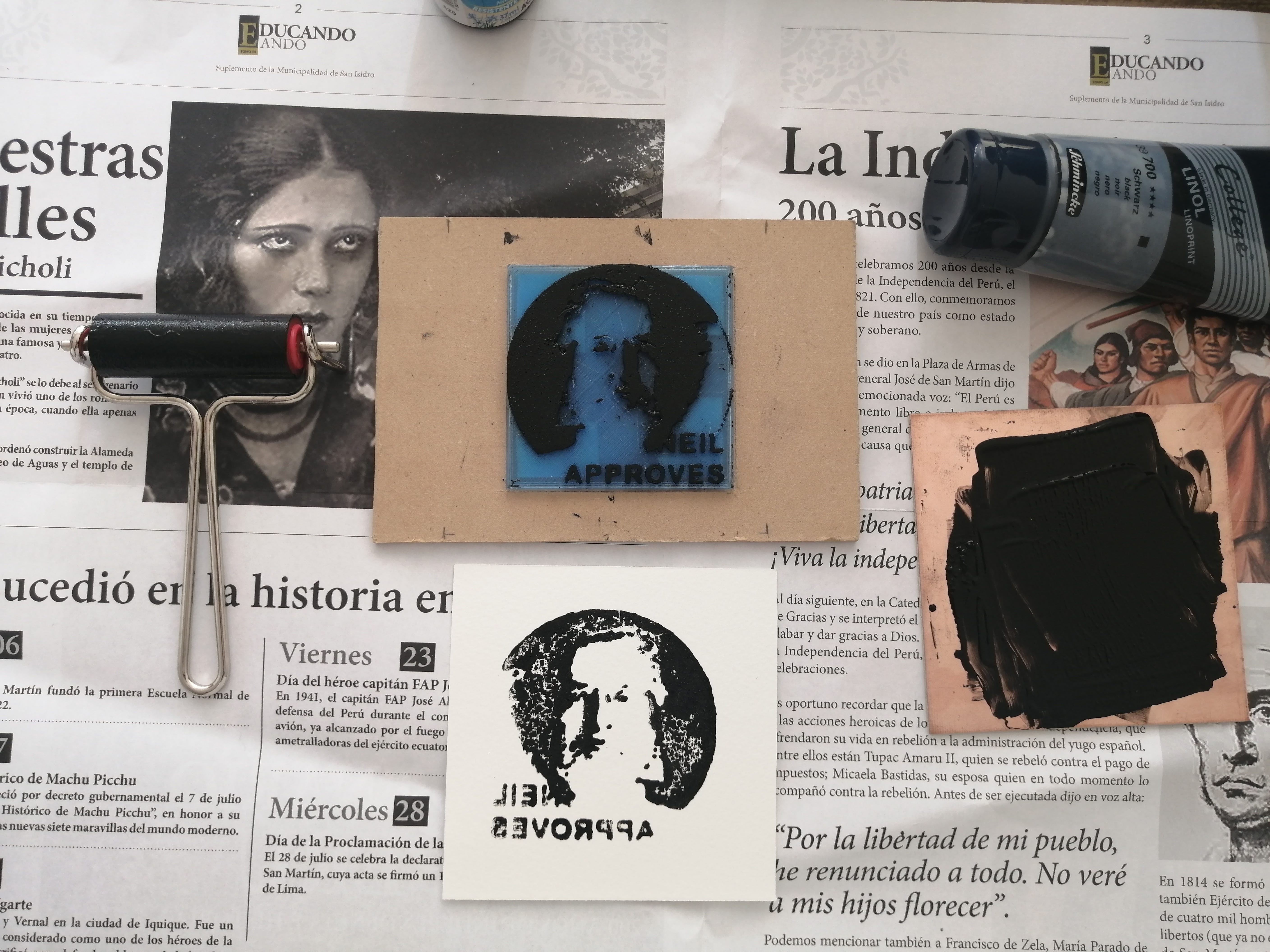
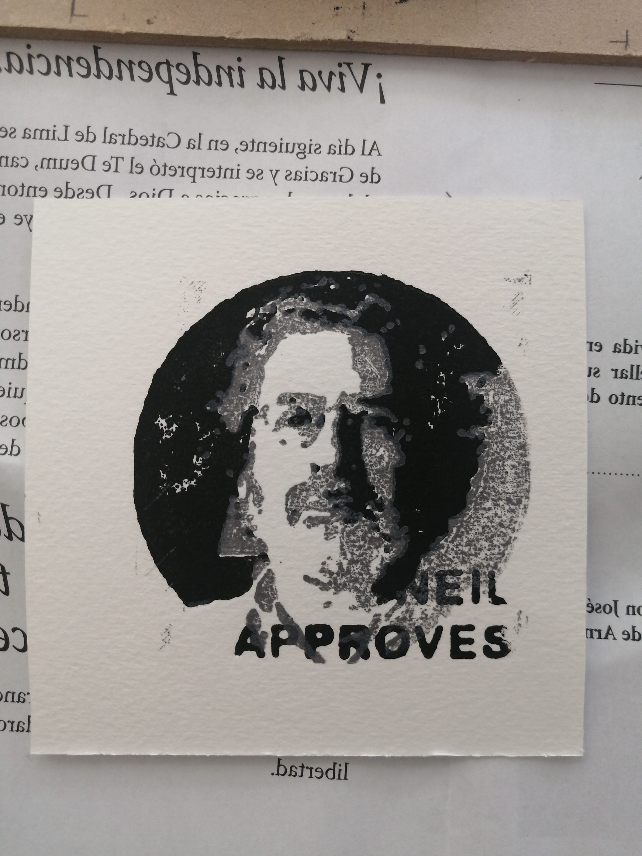
As a newbie in press printing I’ve made many mistakes to get a decent print, first I wasn't using the right ink, next I was using the wrong paper, and then, I was using the wrong technique to set the ink. But after a couple of tries and thanks to my dear artist friend JimenaMia that lend me some ink and papers, I was able to get decent results.
Design files
Download the machine cutting files (.3dm) here
Download Neil matrices for 3d printing here
Download the machine Arduino code (.ino) here
Automated printing press machine in action: