Assigment #11
Output devices
The 11th week of the Fab Academy program is about output devices, and use a controller to instruct a device to do something.
1 – components
Once again, due to the Corona virus pandemic I cannot acces the lab, and therefore I’m going to use again an Arduino Board to do my assignment.
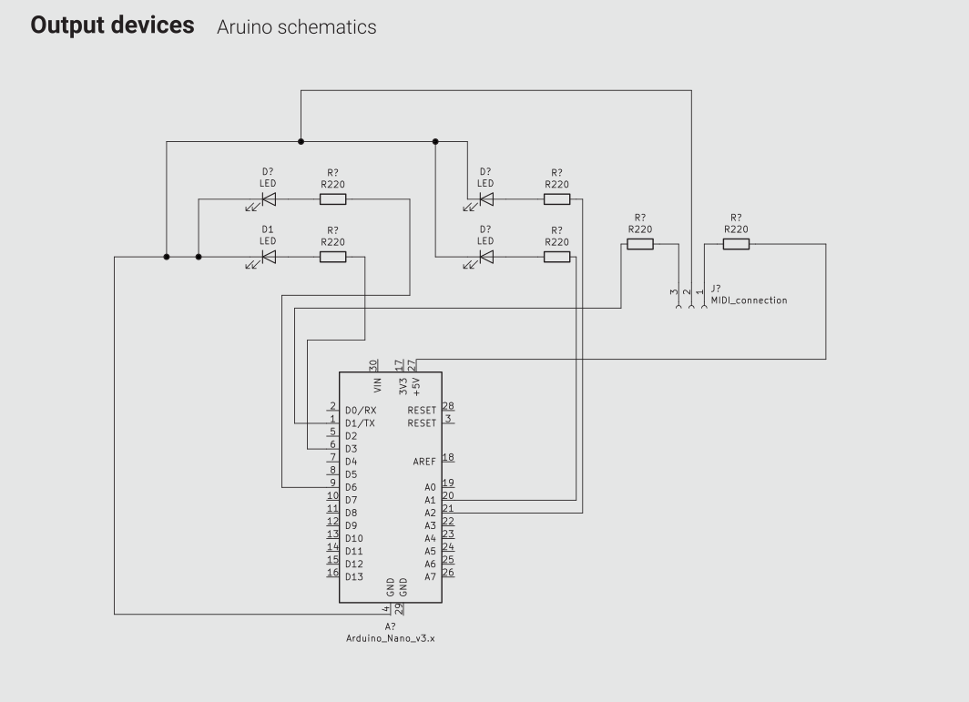
What I’m going to do is to connect the input device assignments that I’ve done two weeks ago with output devices that will provide a visual feedback of what the device is doing plus of course a MIDI output that will allow me to connect the device with a music production software and start making some noise!
To be a little more specific, the output devices will be the following:
- 1 x MIDI socket that will send out Midi notes and Midi CC
- 1 x LED that will blink constantly in order to communicate that the device is running
- 1 X LED that will blink when a MIDI note is sent
- 2 x LEDs that will blink when MIDI CC is sent, with variable brightness to also show a representation of the value (the higher the value, the brighter the light)
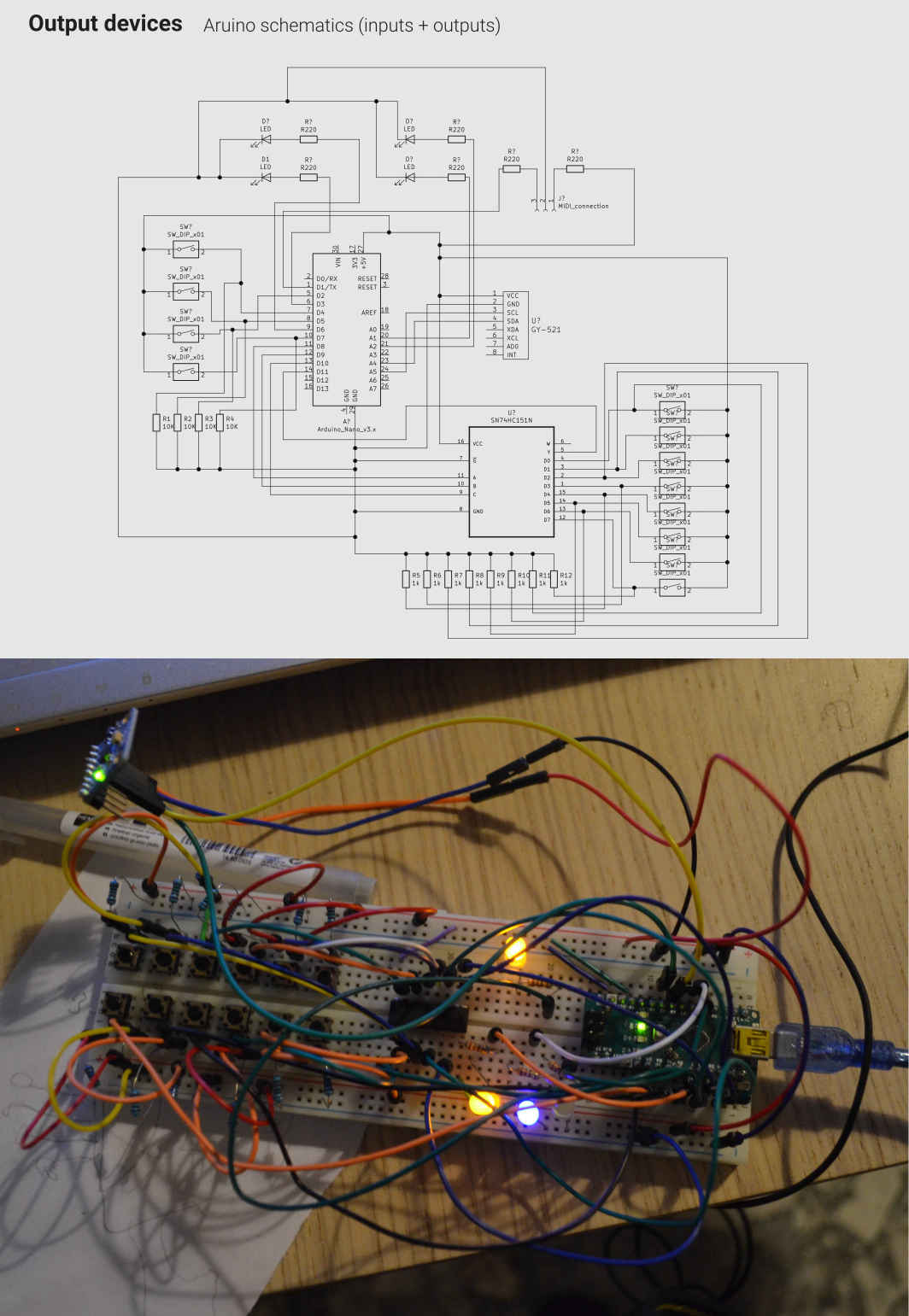
I'm going to add this output devices to the board I did for the input device assignment.
2 – code
The code it’s quite long, but not that complicated. What I did is basically use an analogWrite command to control the brightness of the LEDs, that are connected to the PWM pins, and create a new int that is mapped across the movement of the gyroscope. I also added s LED that is on if a button is pushed (and therefore the device is sendong a midi note) and another LED that is always on if the device is active and it will work as an on/off signal.
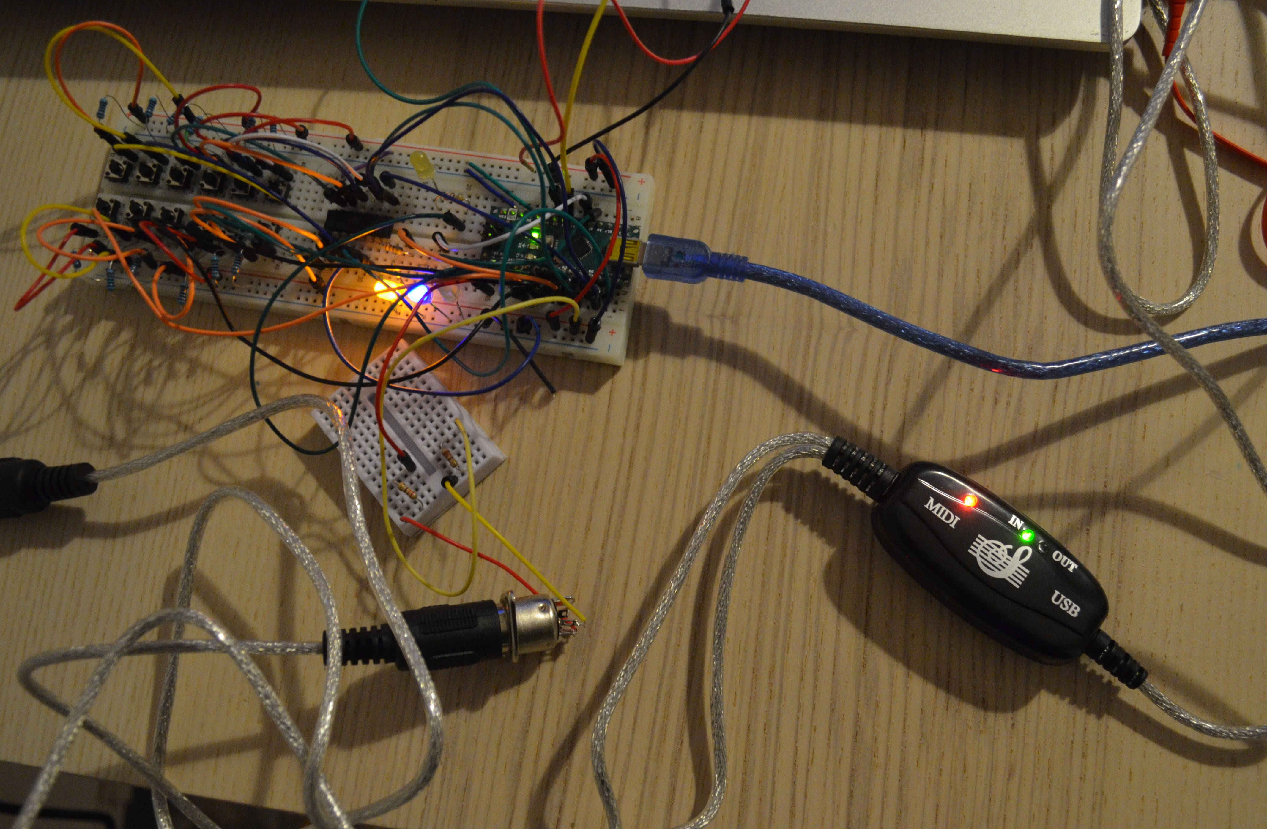
3 – testing the device
Once the IDE sent all the code to the controller, I attached a MIDI to USB socket to my device. I had to adjust a little the baud rate of the serial port, but except for that everything went quite smooth. Then I mapped all the movements of the controller using the open source software LMMS (here a tutorial about how map the midi controller to the instruments available in the application). The only weird thing that happent is that at some point I noticed that the GND pin of the MIDI socket broke, but everything was still working perfectly. Of course I'm going to fix it but I would like to research how that could possiby be.
4 – designing a board
To complete my assignment I designed a board that could allow a user to use the output devices that I worked with without using an Arduino.
For the design of this board I'm going to skip the input devices, that because I didn't want to overlap the previous assignment and the final project board.
Te CoVid emergency made impossible the production of the PCB, but I still designed it to practice my skills.
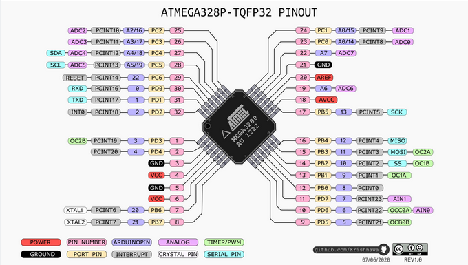
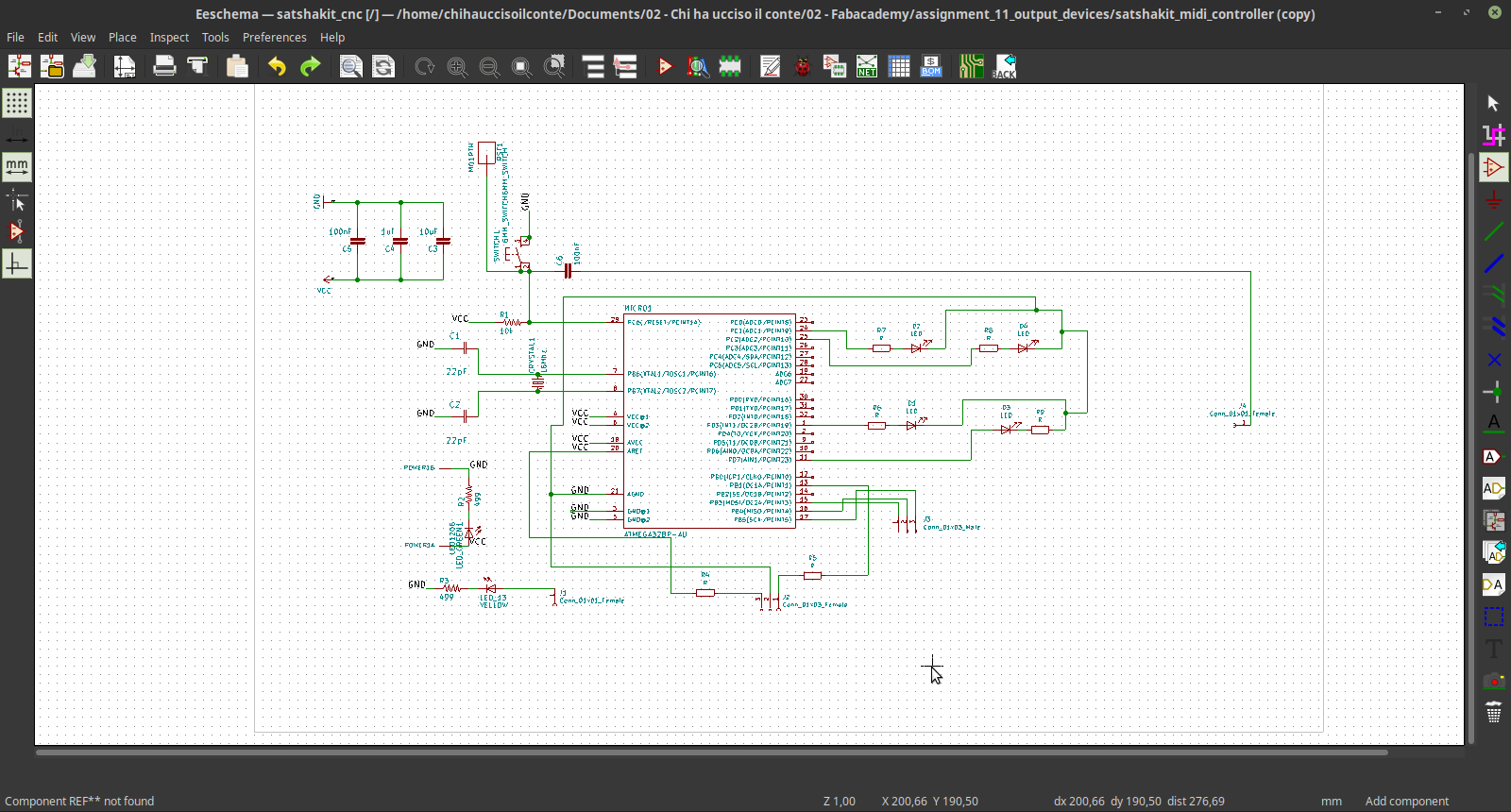
The controller I'm going to use is again the ATmega328P, and I used KiCAD to design the circuit.
By analising the pinout of the controller I found how to connect all the components.
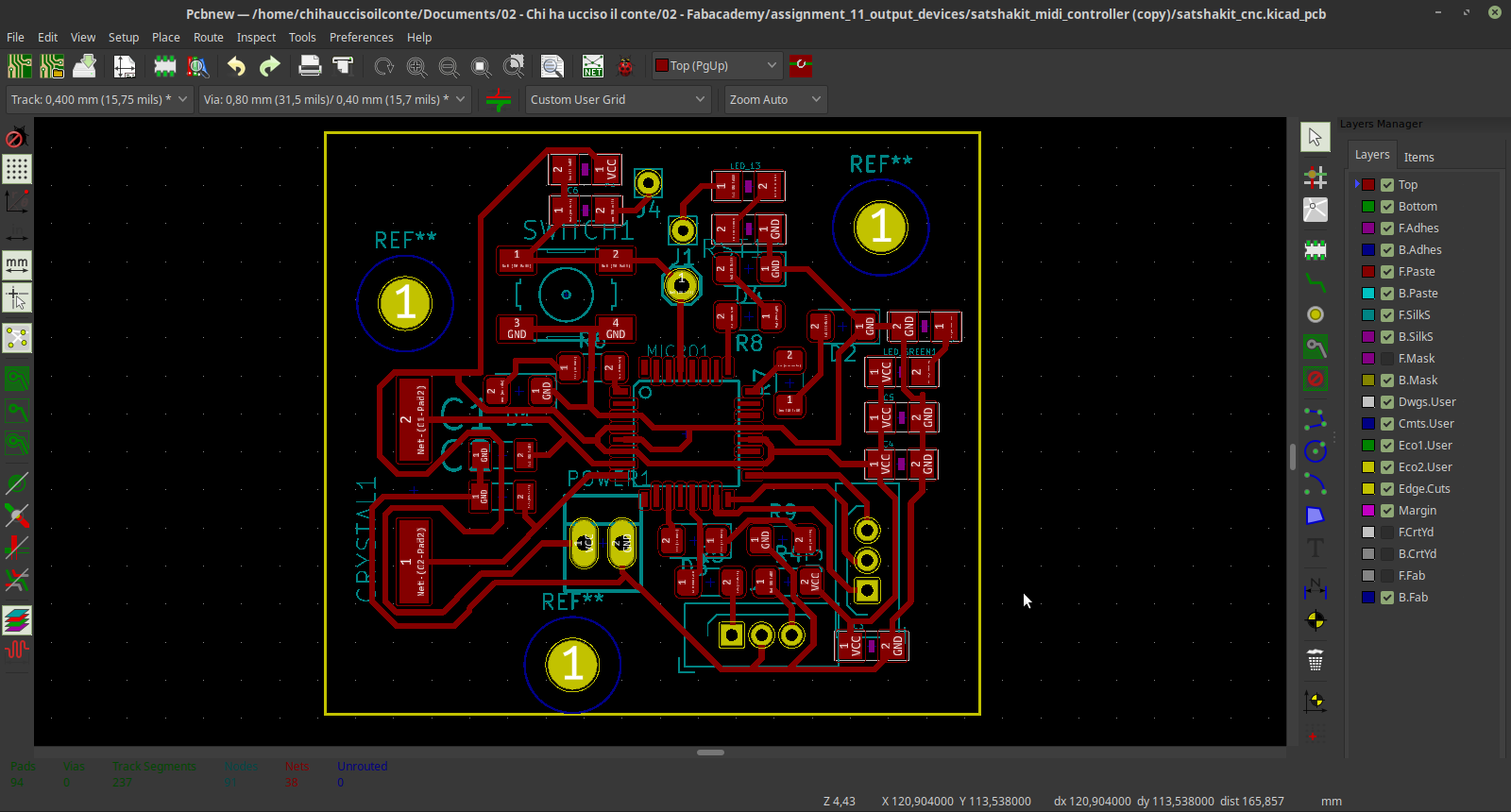
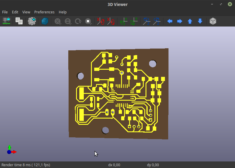
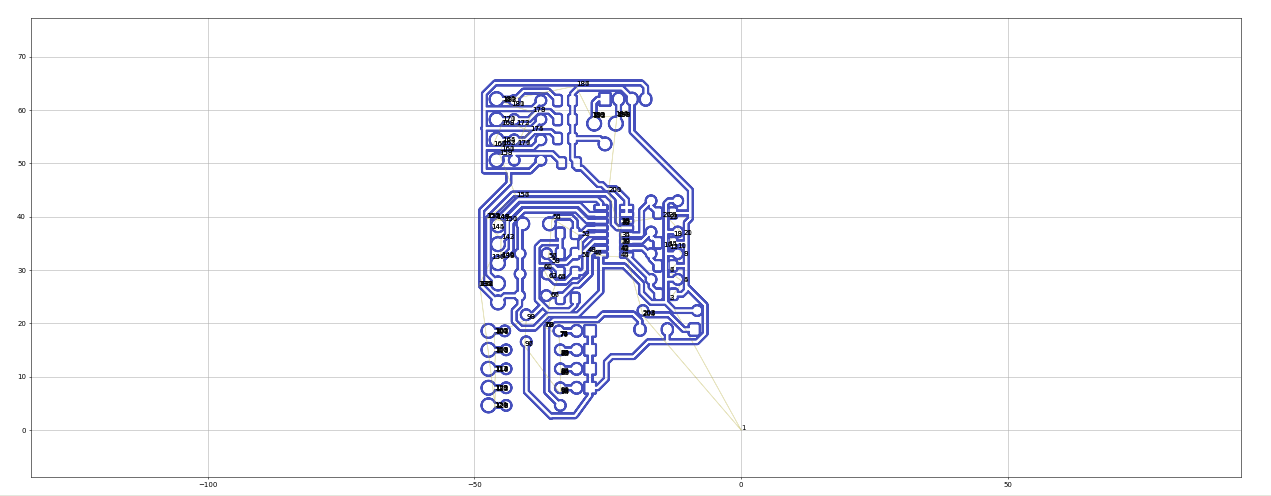
Then I moved to the PCB design and did the routing. Once again, it was not possible to mill the PCB, but we can still have an idea of how the resuld can be by using the 3d viewer of KiCAD.
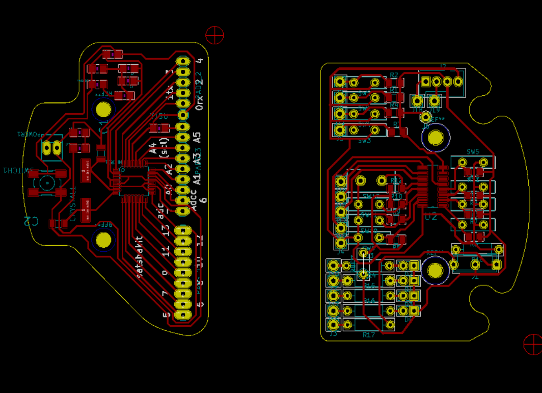
5 – board for final project
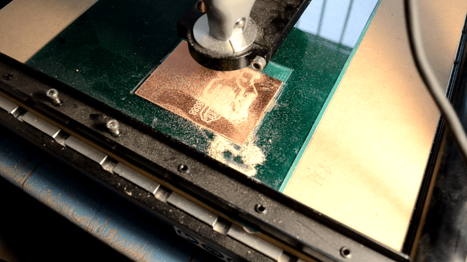
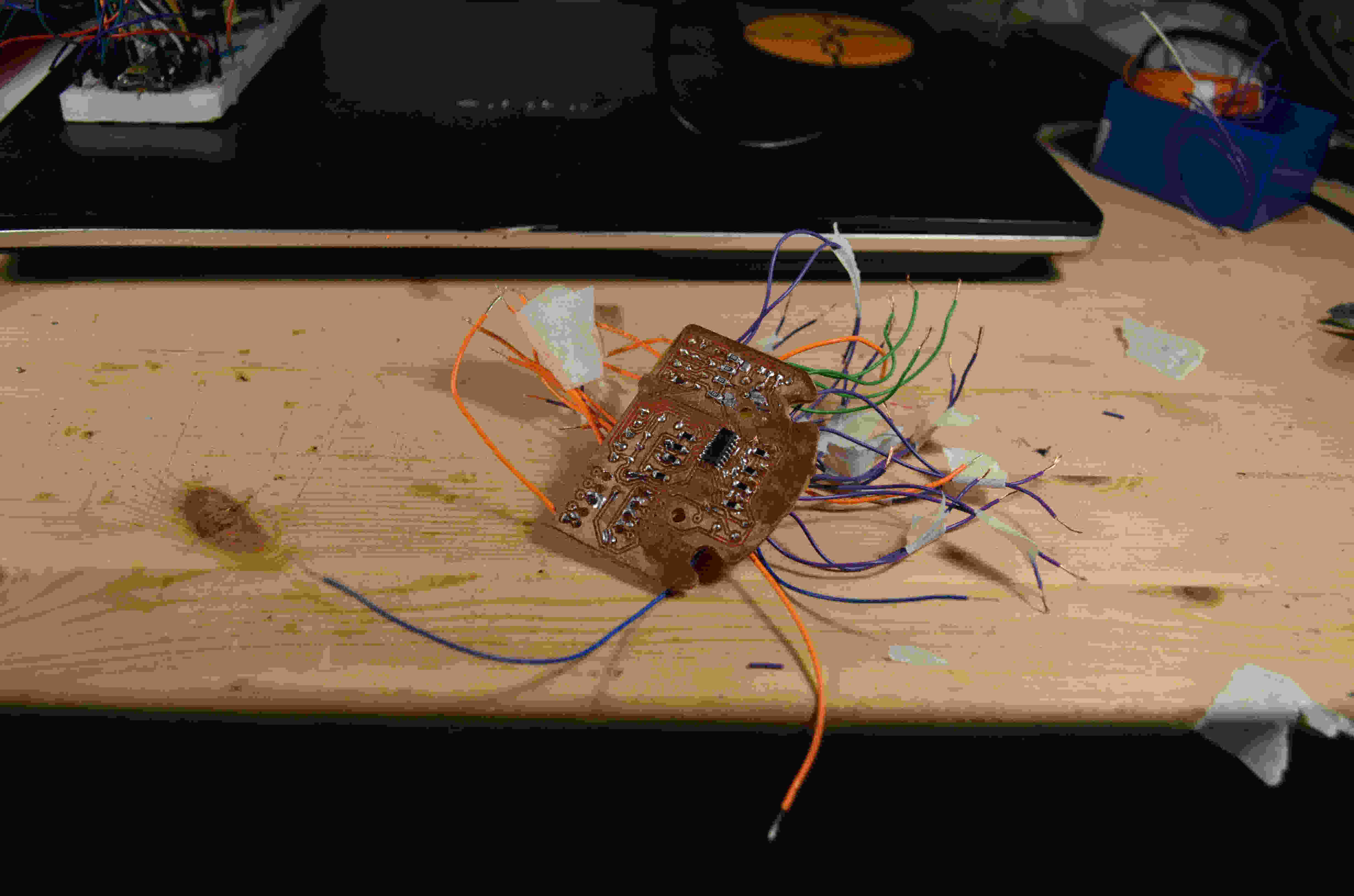
So, the code and the prototype for my input and output devices is done, and I moved to KiCAD do turn this breadboard into a proper circuit. The circuit will work as a support board for the satchakit I made during the electronic design week.
I used FlatCAM to make a gcode, and the stepcraft to mill the PCB.
You can see the final output of this work om my final project page.
source files
Here are all the source files for the Output Devices assignment:
1 - code with LED + MIDI
2 - board with ATmega328P