Assigment #6
Electronics design
The 6th assignment of the Fabacademy is Electronics design. To accomplish this achievement I decided to pick once again (like in the circuit production assignment) an Attiny45 and use it to make a hello board as requested by Neil during his lesson. Although I’m a little familiar with electronics, this will be the first time I go so deep into the topic.
1 – analisys of the controller and schematics design
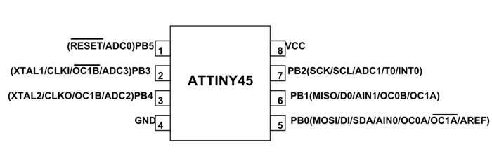
The first thing I did was to analize the datasheet of the Attiny and see what each pin does.
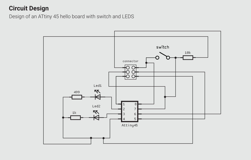
Then I decided to add 2 LEDS and a switch as requested.
I double checked my work analysing the work of former fabacademy students.
In particular I saw what Rutuja Patel did in 2018.
Calculating all the values I came up with a schematic that (hopefully) will repreent a working hello world board.
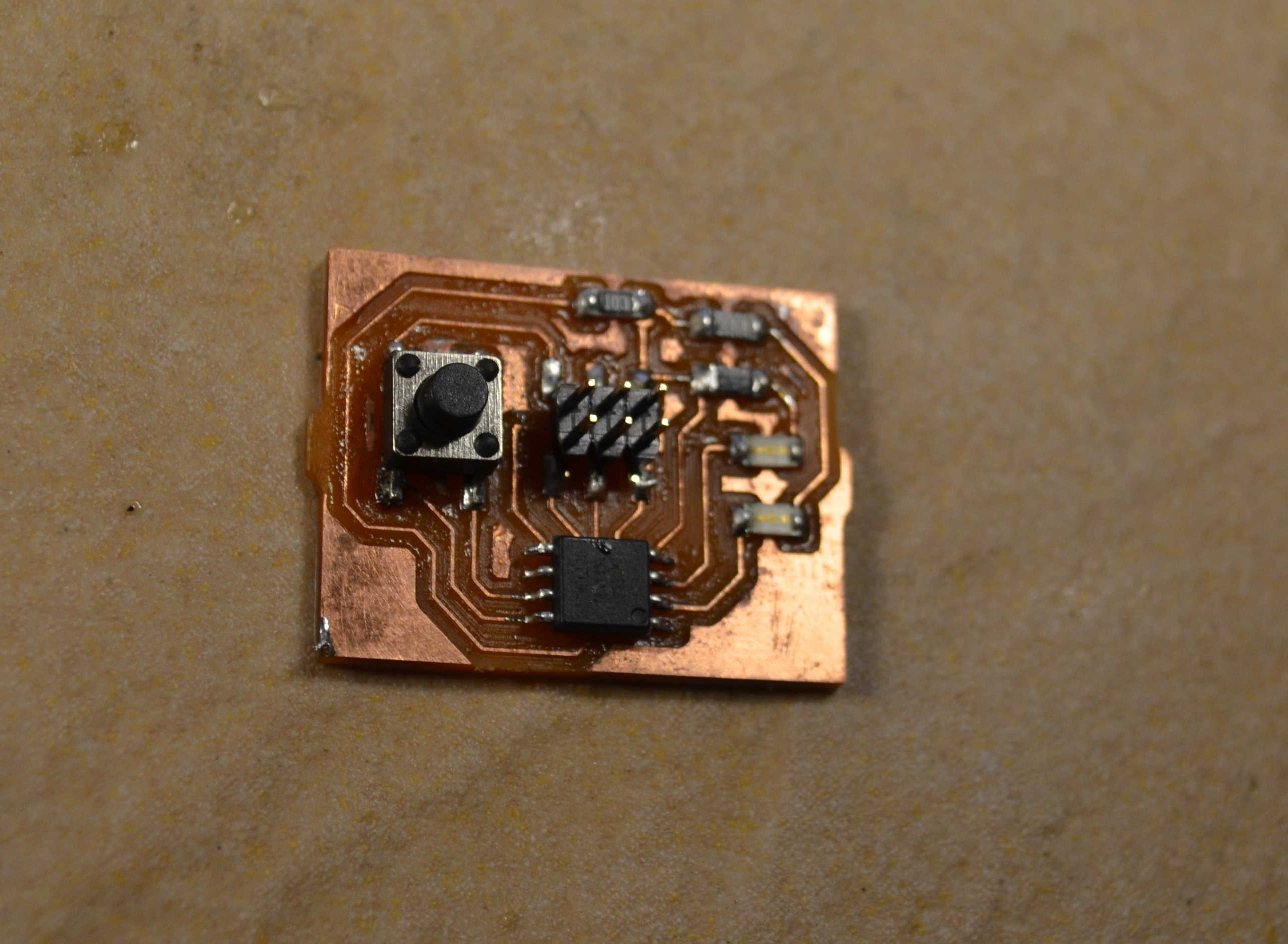
The result is a board that uses the following components:
- 1 x Attiny45
- 2 x LEDs
- 1 x 10k resistor
- 1 x 499 resistor
- 1 x 1k resistor
- 1 x 2 x 3 pin connector
2 – designing the board with KiCAD
Once I came up with a schematic, it was time to actually design my Helloboard.
Kicad works a little bit like Platos philosophy:
Theres a first phase where you design a schematic (world of ideas) a second phase where you link each part of the schematic to a specific footprint called netlist (like the demiurge). And then you shape the PCB itself (the physical universe!), so, those are exactly the steps I followed to make my board.
I first added all the components of my schematic in a sheet and connected them. The circuit is quite messy and many connetions overlap, but at this stage it’s not really a concern.
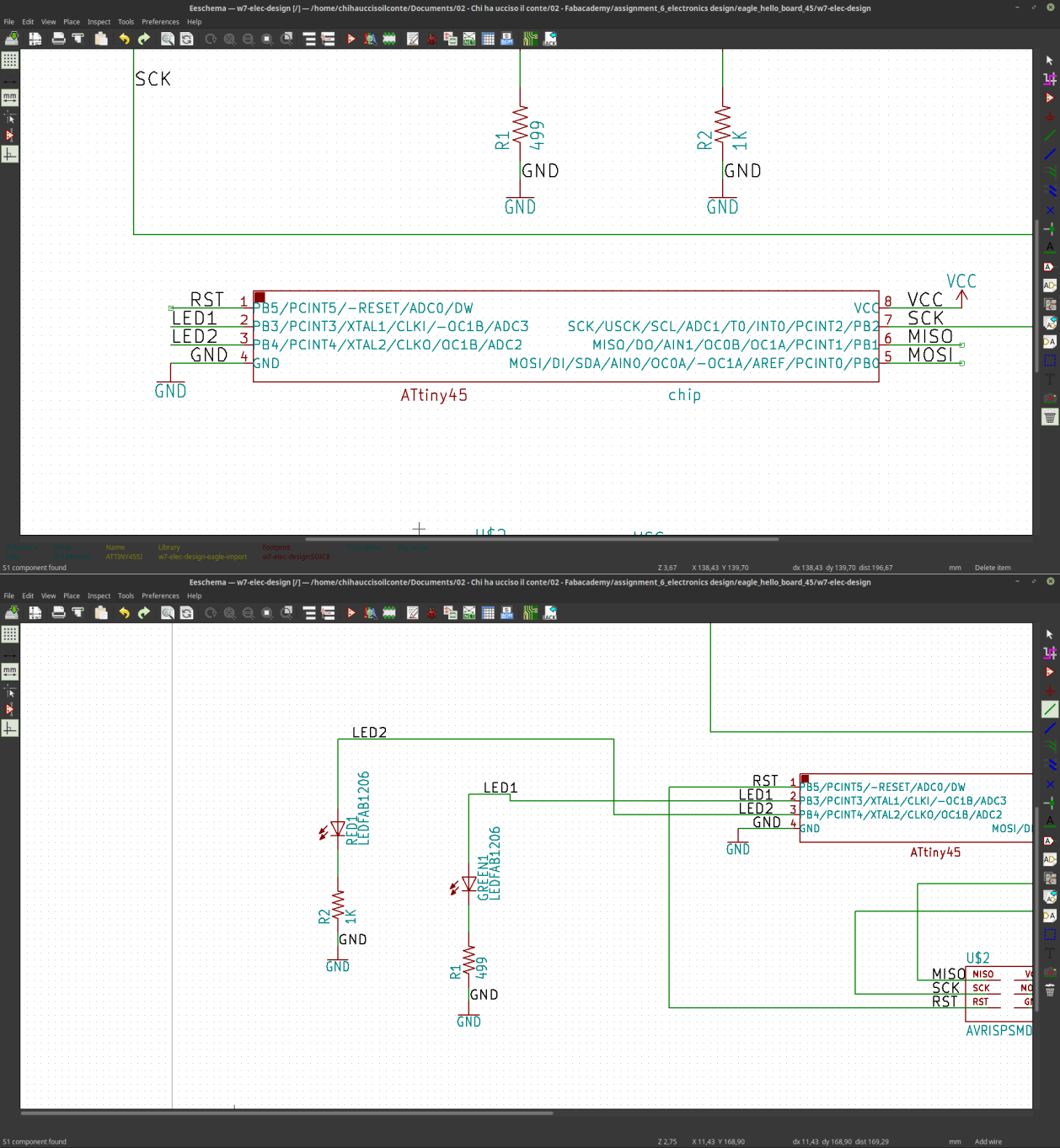
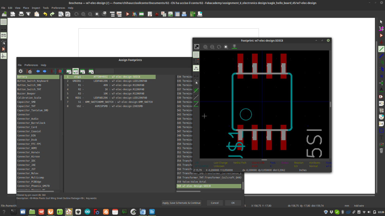
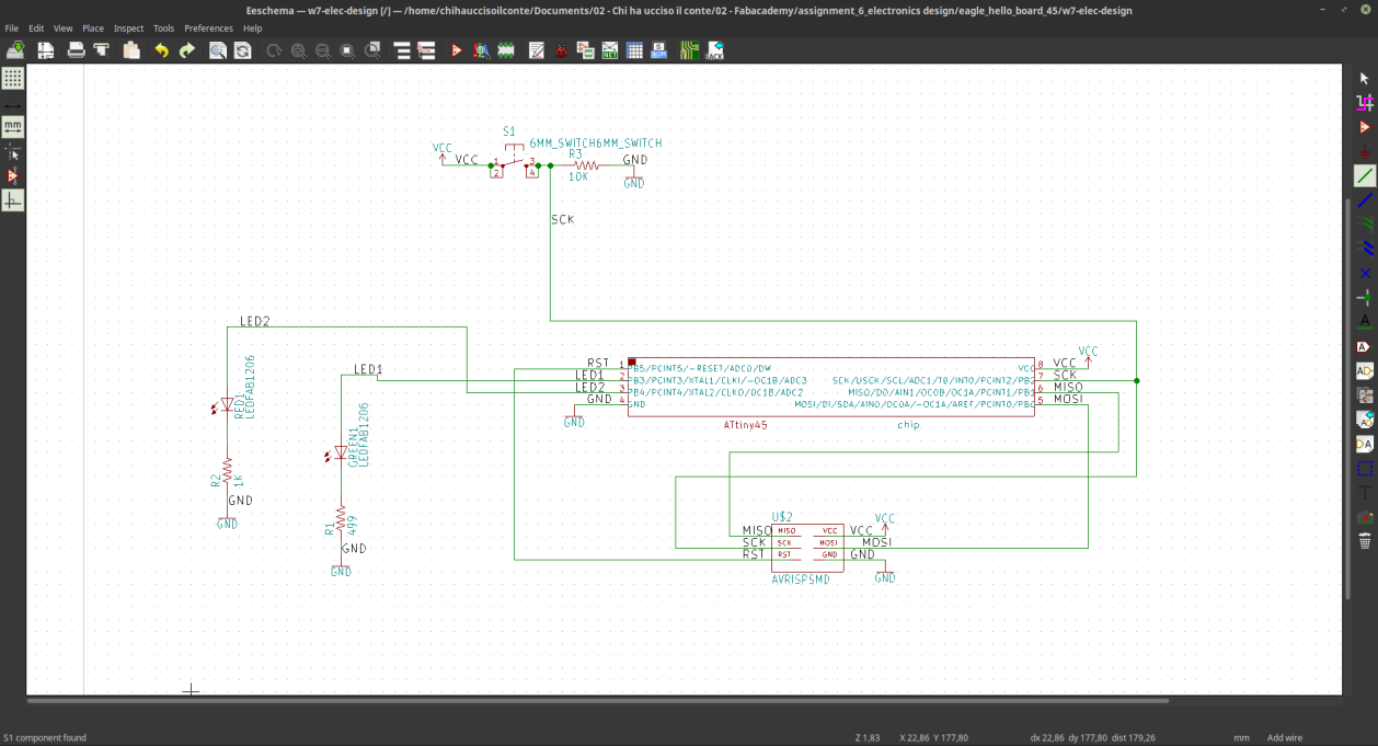 Once I was happy with the schema I opened the “assign PCB component” menù, and explored the libraries availabe from KiCAD. The components I’m using are quite basic, and therefore I was able to find all of them without the need of adding extra components to my library. At the end of this process I generated a so called netlist.
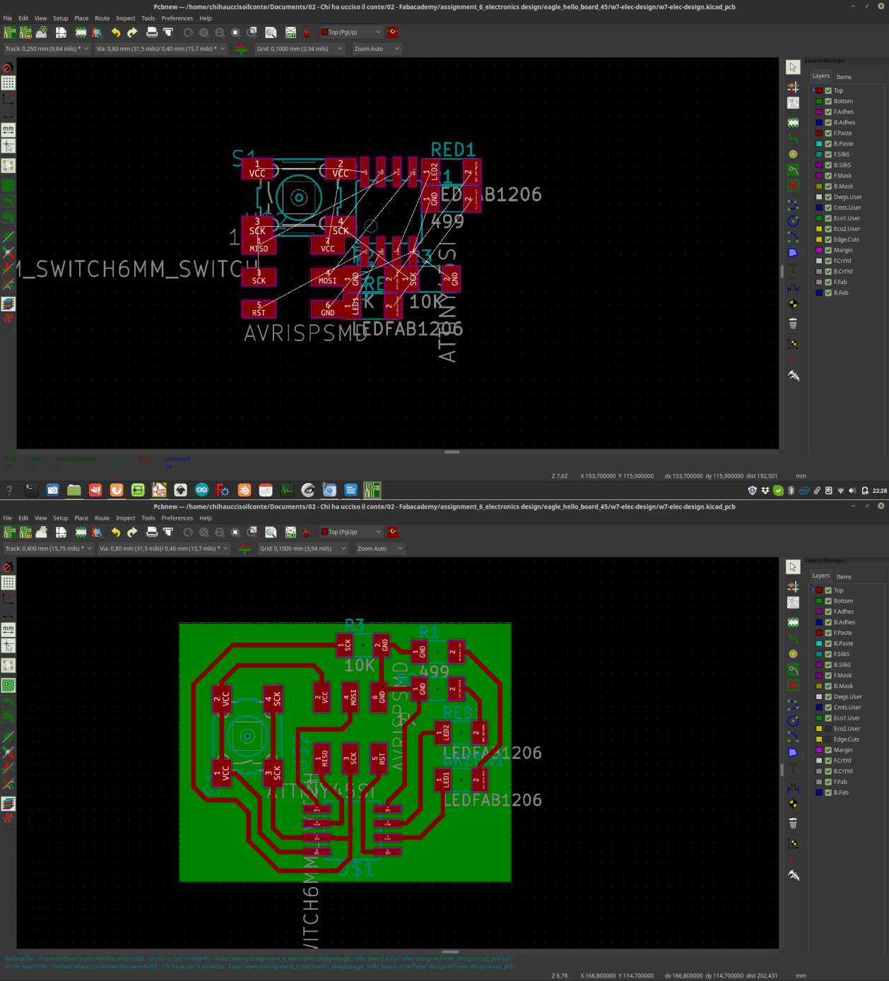
 Next step to this process was to open the PCB editor and call the netlist I just made.
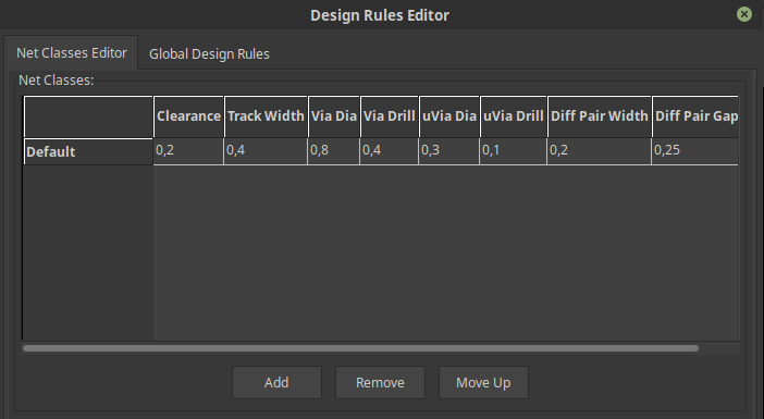
Then I increased a little the thickness of the traces in the Design rules menù so that it’s easier to mill them.
To be alittle more specific, I set a path width of 0.4 (reasonably wide to minimize the risk of wiping out tracks while working with the board), and drill hole to 0.8, and a clearence of 0.2, which is half of the bit I'm going to use to mill the paths.
Next step to this process was to open the PCB editor and call the netlist I just made.
Then I increased a little the thickness of the traces in the Design rules menù so that it’s easier to mill them.
To be alittle more specific, I set a path width of 0.4 (reasonably wide to minimize the risk of wiping out tracks while working with the board), and drill hole to 0.8, and a clearence of 0.2, which is half of the bit I'm going to use to mill the paths.
 I tried to produce a board as compact as possible, and then I created an infill layer below so that it will be possible for me to cut it out using Flatcam (see the circuit production assignment for more info about this).
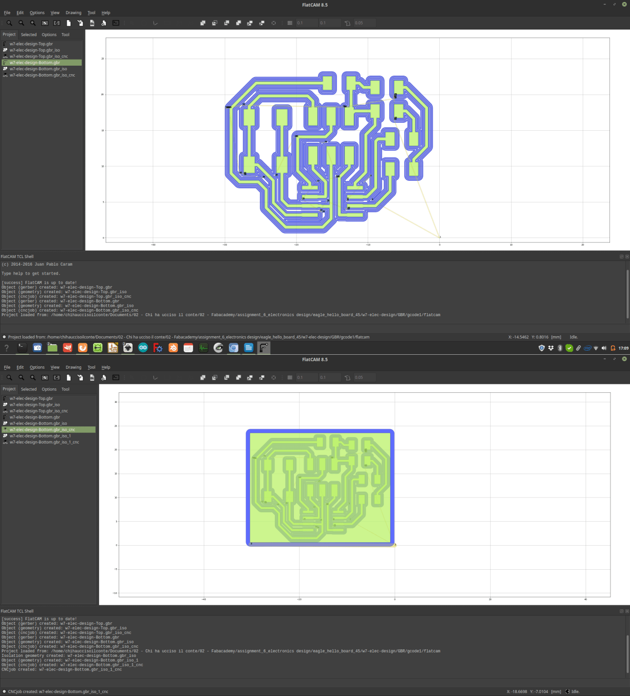
Once I was happy with my PCB I exported my gerber files for milling.
I tried to produce a board as compact as possible, and then I created an infill layer below so that it will be possible for me to cut it out using Flatcam (see the circuit production assignment for more info about this).
Once I was happy with my PCB I exported my gerber files for milling.
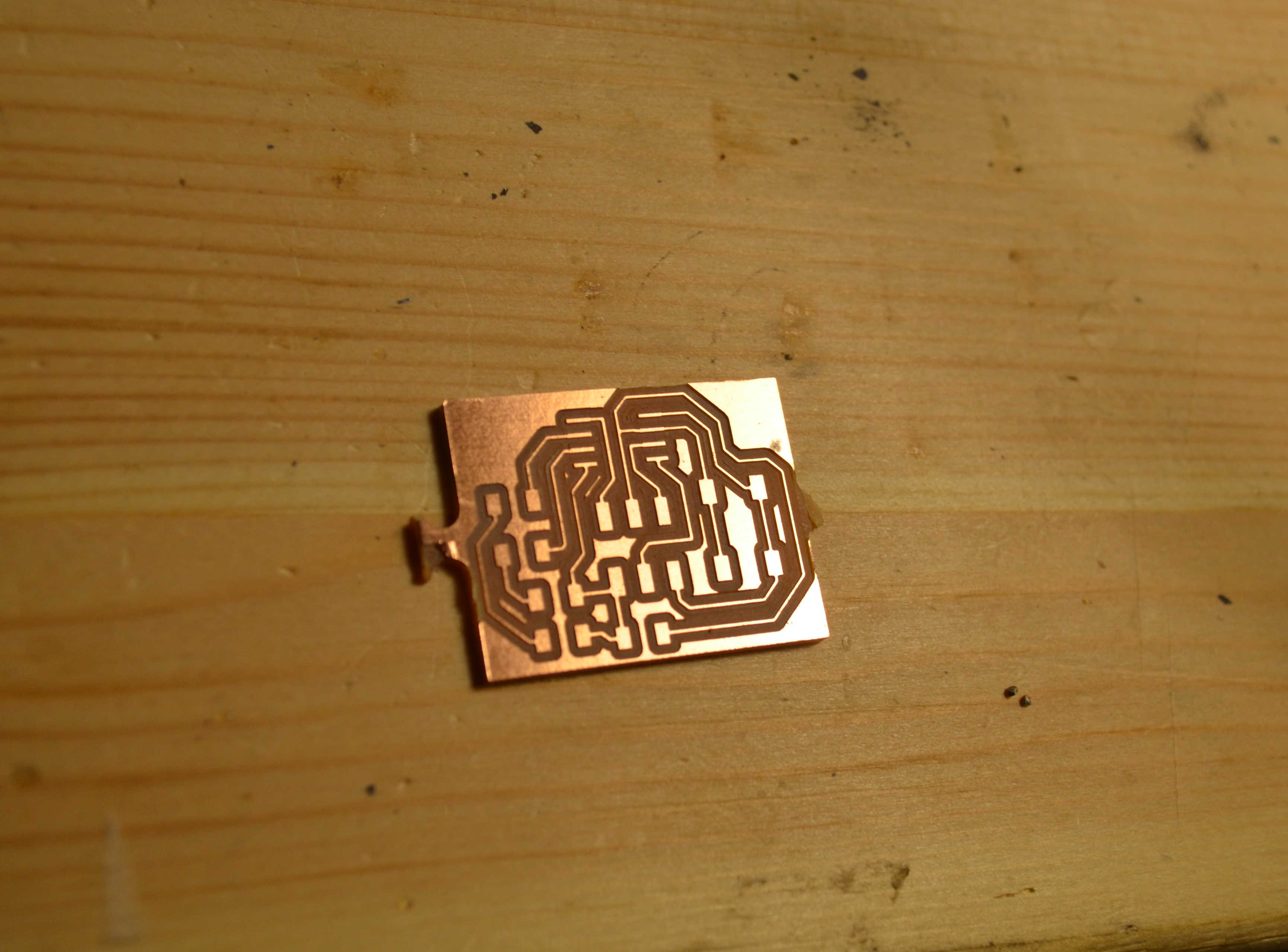
3 – milling the board
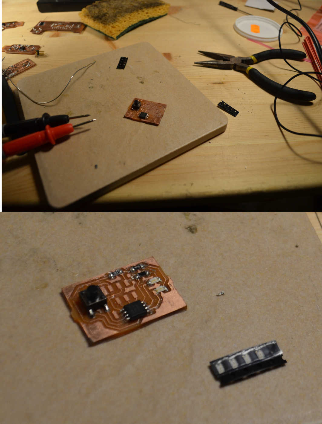
The board I just designed and exported was imported again in FlatCAM, and after generating the gcode, milled with my loyal Stepcraft 2/600 black edition.
4– soldering the components
After this was done I soldered the components on the board. After the hell I’ve being through during the Electronic Production assignment I’ve being very careful and I managed to add all the components without struggling too much (althought I sweat cold all the time...) and, according with the tests I made with the multimeter, all the connections work fine.
5 - Satshakit
Besides the Hello world board, I decided (advised by my local instructor) to produce as well a custom version of the Satchakit .
The satchakit is an arduino-compatible boad designed by former fablab student Daniele Ingrassia. It’s very powerfull and reliable, and since I have a litte bit of experience working with Arduino I thought it could be a good idea to implement this on my final project.
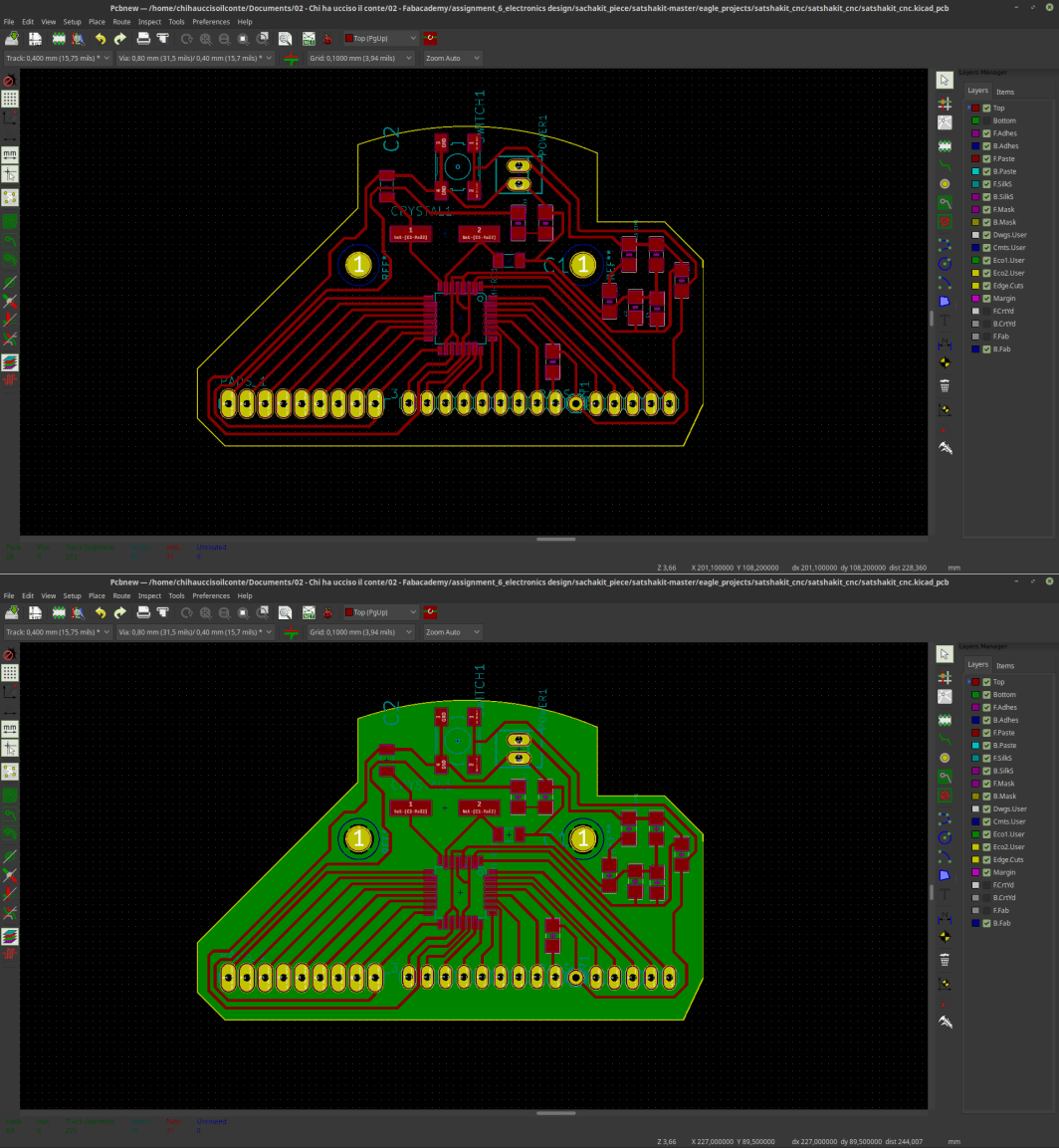
I made a satchakit with a shape that will fit inside the shells previously designed.
The Satchakit uses the following components:
- 1 x ATMEGA328P-AU
- 1 x switch
- 1 x 16Mhz/18pF crystal
- 2 x LEDs
- 2 x 499 resistor
- 1 x 1k resistor
- 2 x 22pF capacitor
- 1 x 10uF capacitor
- 1 x 1uF capacitor
- 2 x pin connector
Just like with the hello board I started with re-doing the schematic on KiCAD, and then once again connected the schematics with the footprint.
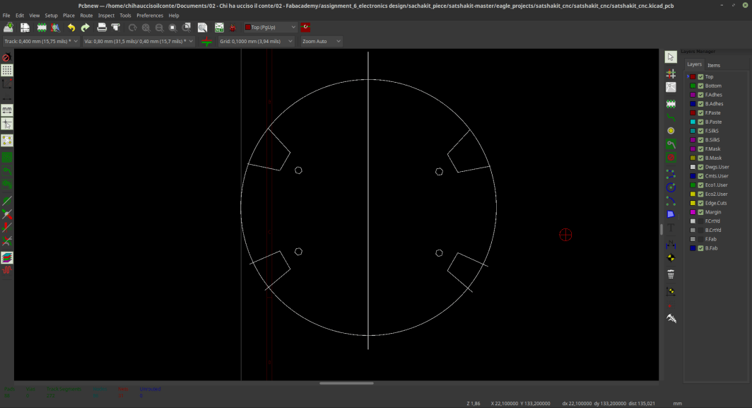
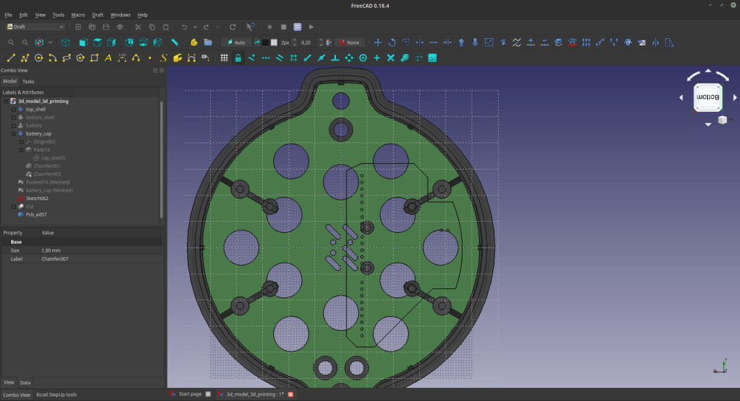
Once in the PCB design page I imported a DWG file representing the position of the elements in the 3d printed shell of my midi controller.
I used those elements as a reference to place mounting holes and to determinate the shape of the board itself.
I then positioned the pins in correspondance with the center of the circle that forms the shape of the device I’ll make, and I’ll keep the other half for input/output devices.
At the end of the process I found myself with an odd shaped circuit (I wanted to make the circuit circular, but it would have been a huge waste of material).
 Before exporting the gerbers I used the KiCAD stepup addon to double check if the size of my pcb is correct. The test was positicve, so, I just carried on and exported the gerber files.
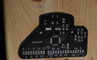
At the time I'm writing this, CoVid is raging all over the world, and because of that it's really hard to acces labs and mill PCBS. So, to experiment with something new and to have a very fine piece for my filan project I commissioned the production of this Sashakit to Seeedstudio.
The result is really good (to solder on this PCB was really smooth...) and the board perfectly fits with the 3D printed parts I designed.
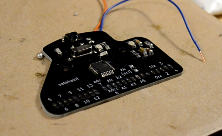 This board works almost as smoothly as a commercial Arduino, and Perhaps I can use it for other assignments.
source files
Here are all the source files for the Electronics Design assignment:
1 – Hello boart attiny45 KiCAD files
2 – Hello boart attiny45 Gbr files
4 - Satshakit Kicad files
5 - Satshakit GBR files