Kinetic Midi Controller
An experimental MIDI controller
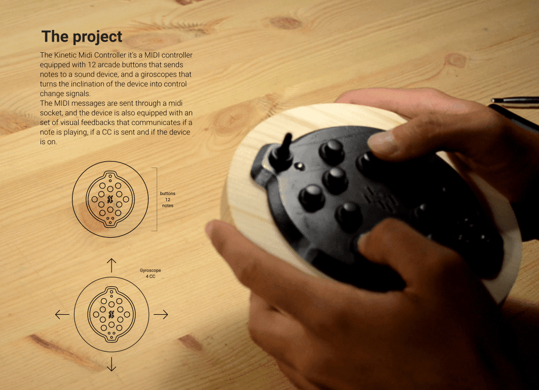
So, my idea for the Fab academy final project is to design a MIDI controller that uses also other sensors in stead of “the usual” buttons and knobs. In fact it appears that (especially in the mainstream market) even if it would be possible to use nearly any kind of sensors to modulate sounds, it is really hard to find music interfaces that are not boxes with buttons and knobs on them. I aim to question this approach and come up with something new. To be a little more specific, I would like to develop an instrument that uses a gyroscope to interact with the sounds. I imagine a device that the user could hold in it’s hands and rotate it around to change the sounds he plays with.
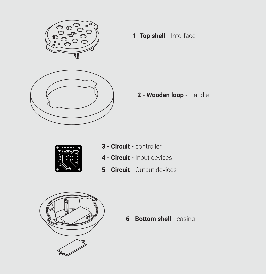
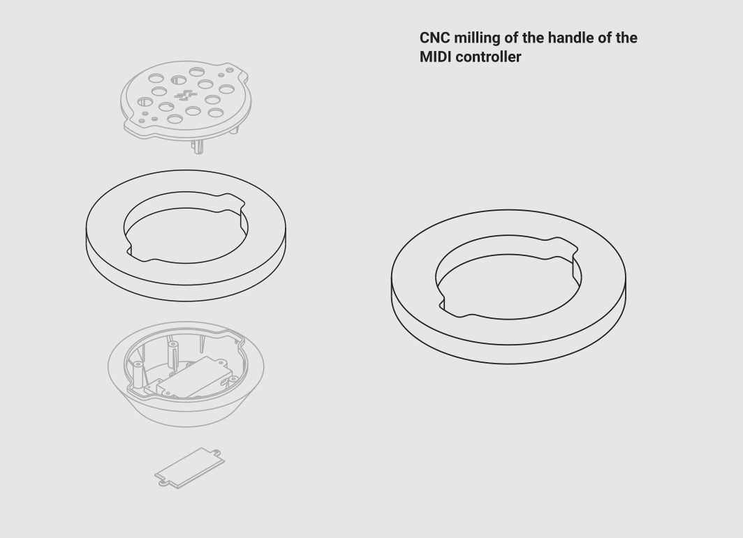
Structure of the device
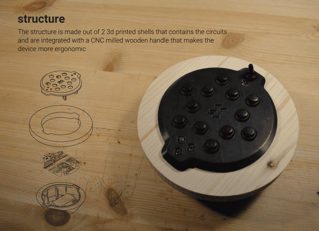
I think that the device is as compact as possible in order to provide an asy and straightforward handling, and at the same time is relatively fast to produce and budget friendly. To achieve that I thought about producing a device based on a sort of “sandwich” where two 3d printed shells contain a wooden element that will be the part that the user will hold. I’ll also try to add some visual feedback to make the users aware of what the sensors are detecting (sketch esploso) On top of the device there will be a set of 12 buttons, and in the center I plan to place the gyroscope.
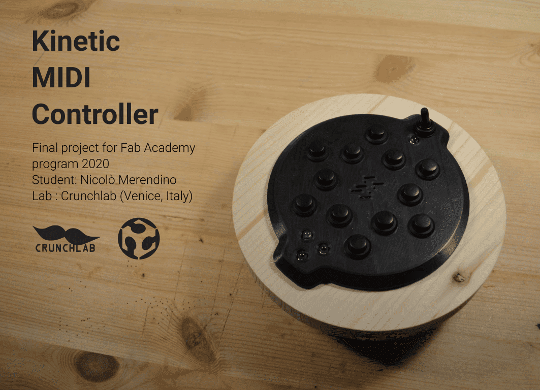
final project for the Fab Academy program 2020
The following paragraphs will describe all the steps I followed to make my final project. During the program I tried as much as I could to match the contet of the assignments with the things I had to do to realise the MIDI controller you are about to see All the materials were graudually added as I covered the assignments of the program.
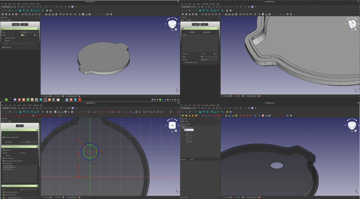
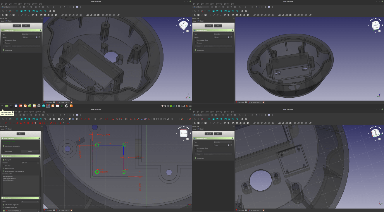
3D - Main volume for the top-shell
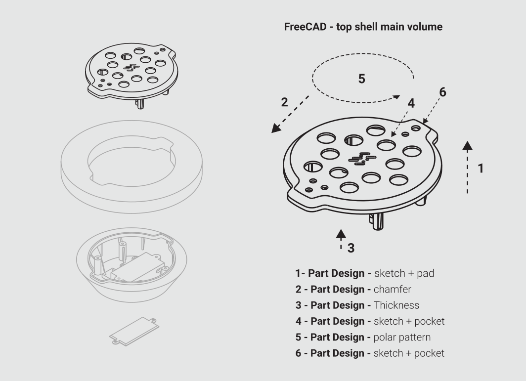
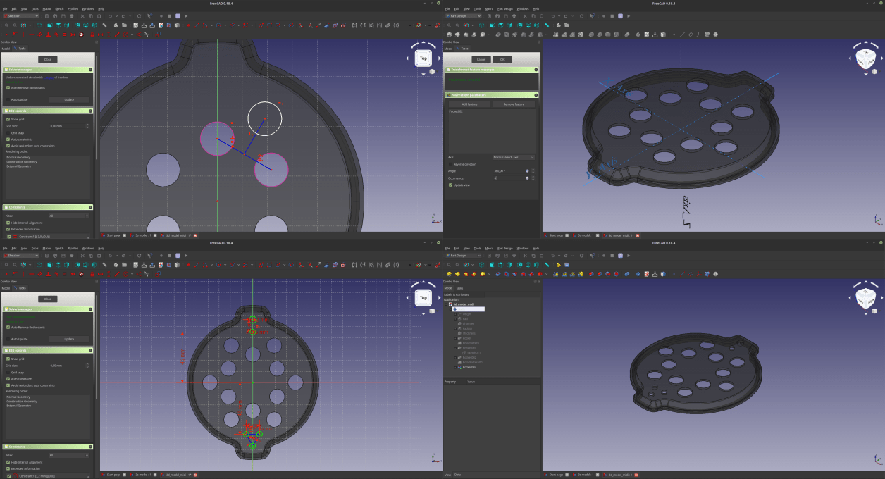
So, the first part I designed was the top shell that will be the top of my “sandwich-shaped” MIDI controller. To do that I used many tools that are inside the FreeCAD “Part Design” workbench: The first thing I did was to create a new part, draw a sketch and then extrude it, using the “pad” command, and repeated to add an element that will go inside the wooden element. Then I used a Chamfer command to smooth the upper part of it, and I applied a thickness to the whole volume Once this was done I used a thickness command, and a sketch + pocket to generate the holes where the buttons will fit. After that I used a Polar Pattern to repeat the holes for 6 times. I made this operation twice to reach the number of 12 holes (as many as the buttons I would like to have in my controller), and again a a sketch + pocket to generate holes for LEDs and switch.
3D - Middle wooden element
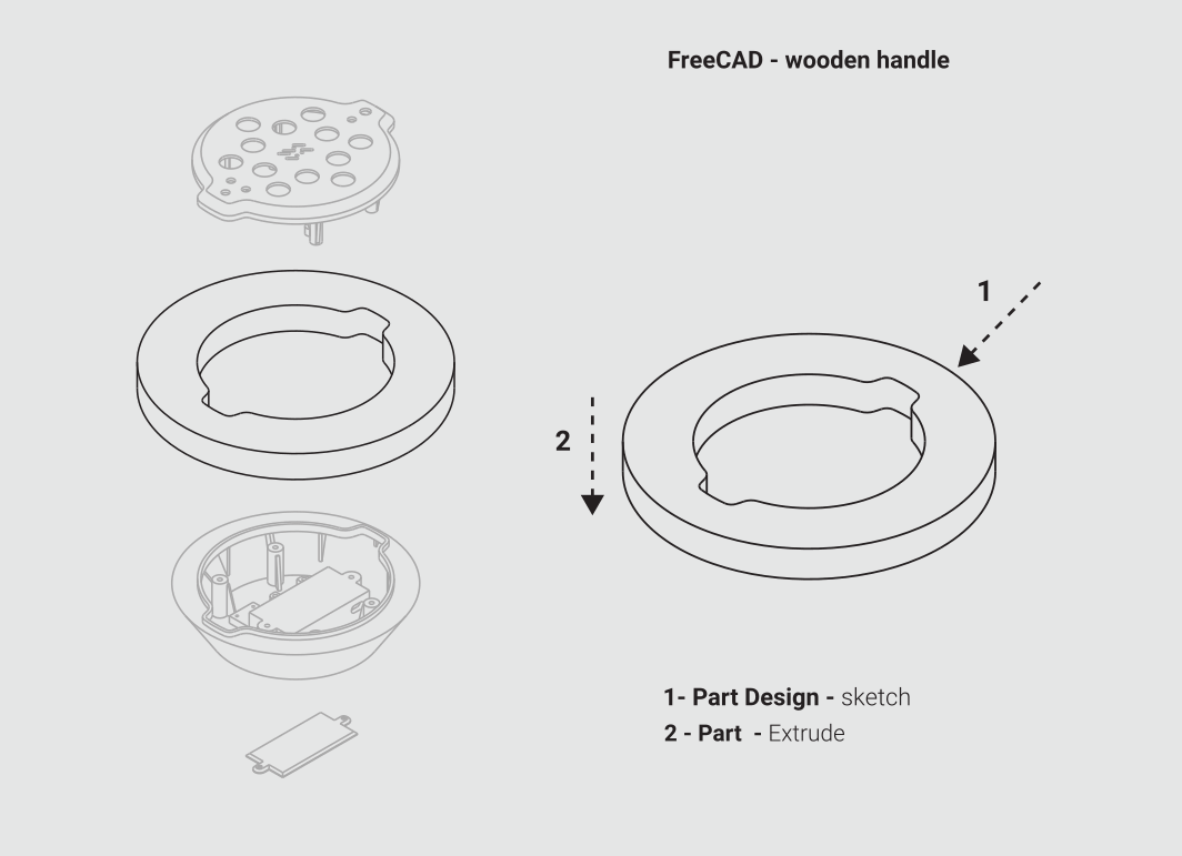
Now that at least the main volume of the top shell it’s complete, it is time to make the middle element that will be held by the user. To do that I made a sketch, and then instead of using the Pad command, I switched to the Part workbench, and used an extrude command to add a thickness to my sketch. In this way the software generate a solid that is not integrated into the part I previously generated, but a new independent component. After changing the color and the transparency of this element I moved to the next part
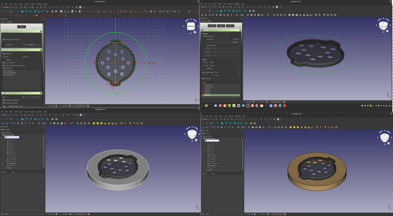
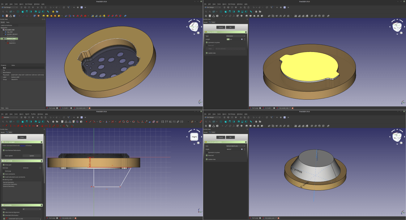
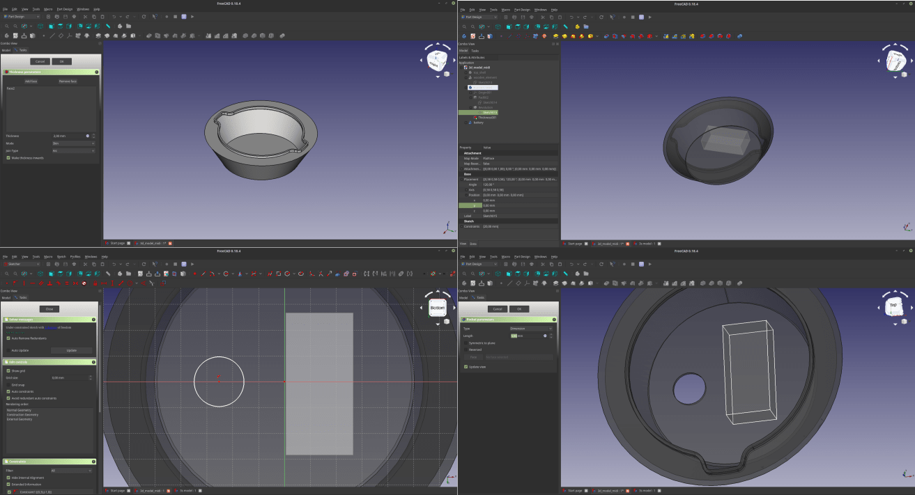
3D - Bottom shell mail volume
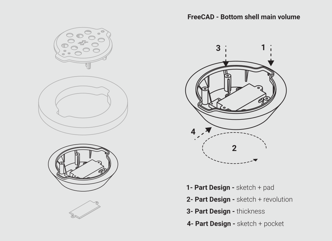
Now it’s time to design the bottom shell of the device, that will contain the battery, the MIDI socket and a tag to mark the device with my name. To do that, I start by creating a new part, and then drawing a sketch. I pad the sketch in such a way that goes inside the wooden element, and sticks a little out. After that I draw a new sketch that will be the profile of the shell, making sure there’s an intersection between the upper side of the sketch and the pad previously made. At this point I select the sketch and I make a revolution command to generate a rotational solid. I apply a thickness to the volume to make it an empty shell. Then I make a small solid that will represent the battery. In this way I can see if the shell I made, and if it’s not big enough I can edit the revolved sketch to fit it. Last thing to do at this point is to dig a hole for the MIDI socket. I draw a circular sketch at the end of the volume I’m working on, and use a pocket command to make a hole in it.
Now that I have all the 3 volumes, I can start to work on the elements that will connect them.
3D - Top shell details
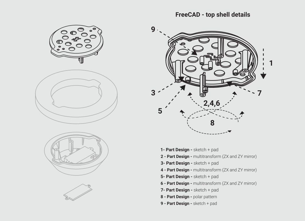
I extruded a column at the bottom of the top shell that will work as a connection with the bottom shell. To do that I used a sketch + pad command. Then I used a multiple feature to mirror twice this element, and I repeated this process for the PCB supports and for some supports that together with the circular array of a little slit, will strengthen the shell. Last thing was to add another element to attach the gyroscope.
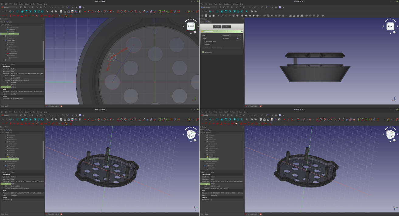
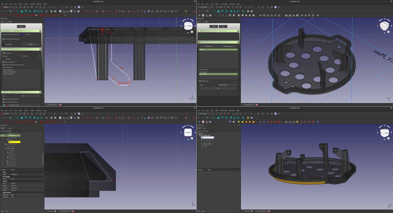
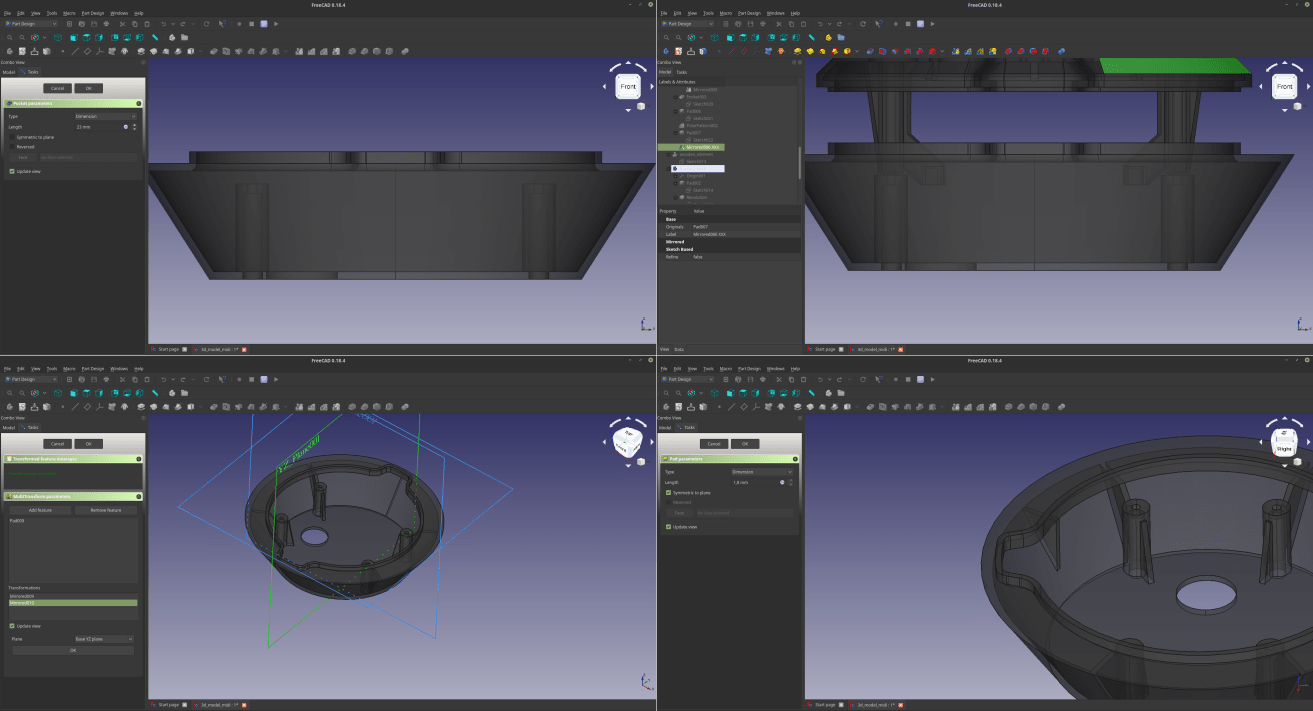
3D - Bottom shell details
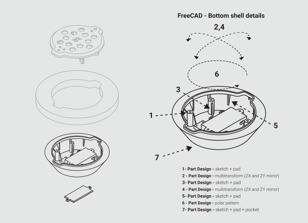
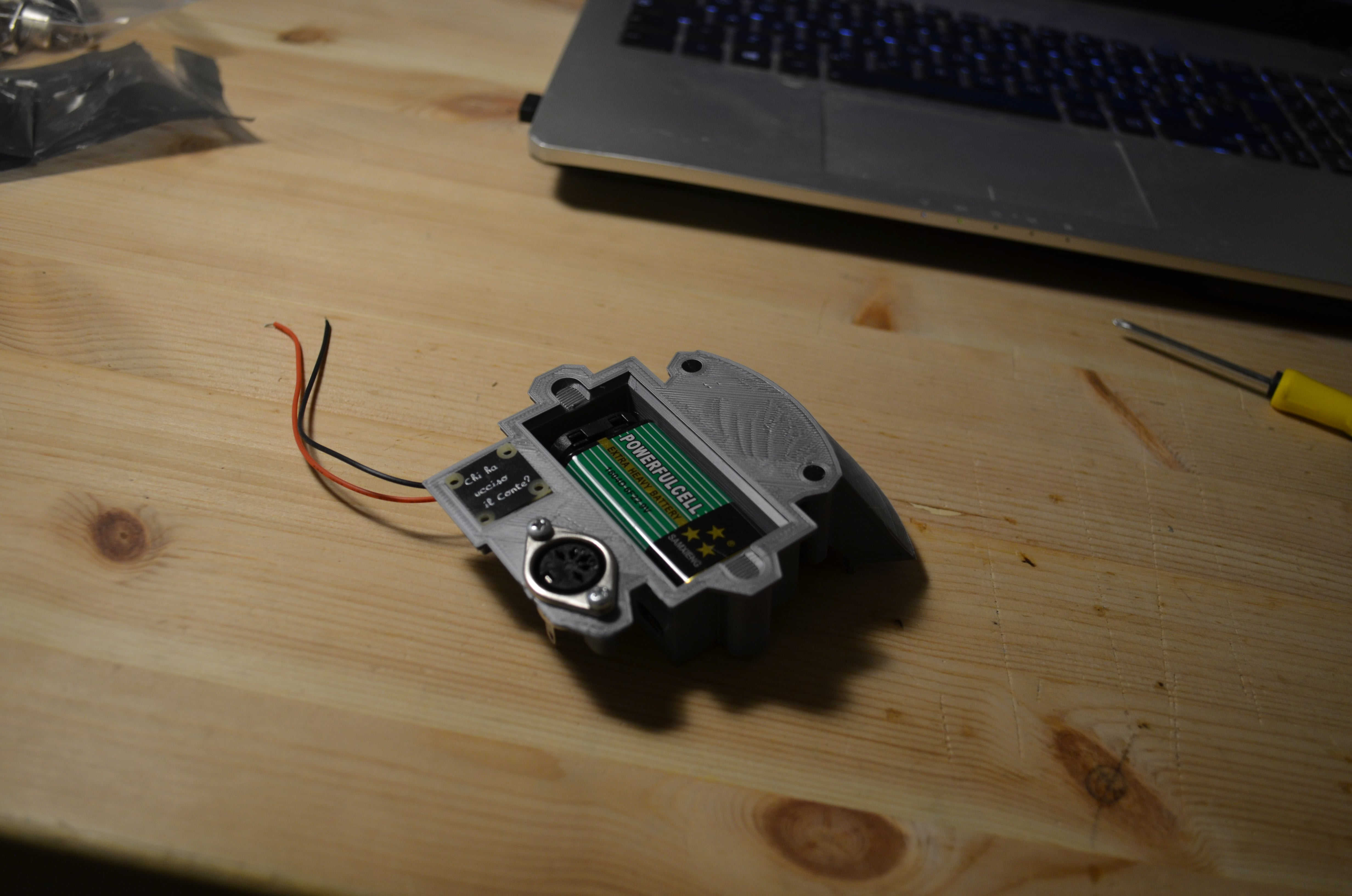
The process that lead to the bottom shell re nearly the same as the ones needed to design the top shell, the only significant difference in this procedure is that I also had to make a (long…) series of pad/pocket to make the battery slot, the support for the MIDI socket and the tag. I used similar commands to realize a cap to close the battery slot.
2D - design a mark to communicate the gyroscope position
Generally when working with CAD you start with 2D and then you move to 3D, but in this case (not counting the lot of 2d sketches that are part of the 3d model) the things went the other way around… In fact I used Inkscape to work on an element that will be placed in correspondence with the position of the gyroscope, so that the user will know that there’s something important in the center of the device, but at the same time I don’t want this sign to be too obvious. To Design such a thing in an agile and effective way I switched to Inkscape. After a few attempts I went for a quite twisted concept, which is a representation in morse code of the XY axis that the gyroscope will detect to tweak the sound. To design the pattern I used the bezier commands, but to use it in freeCAD I need to convert the thickness of the vectors I’m using into a complete shape that can be extruded. To do that I use the command “stroke to path”, and that was it.
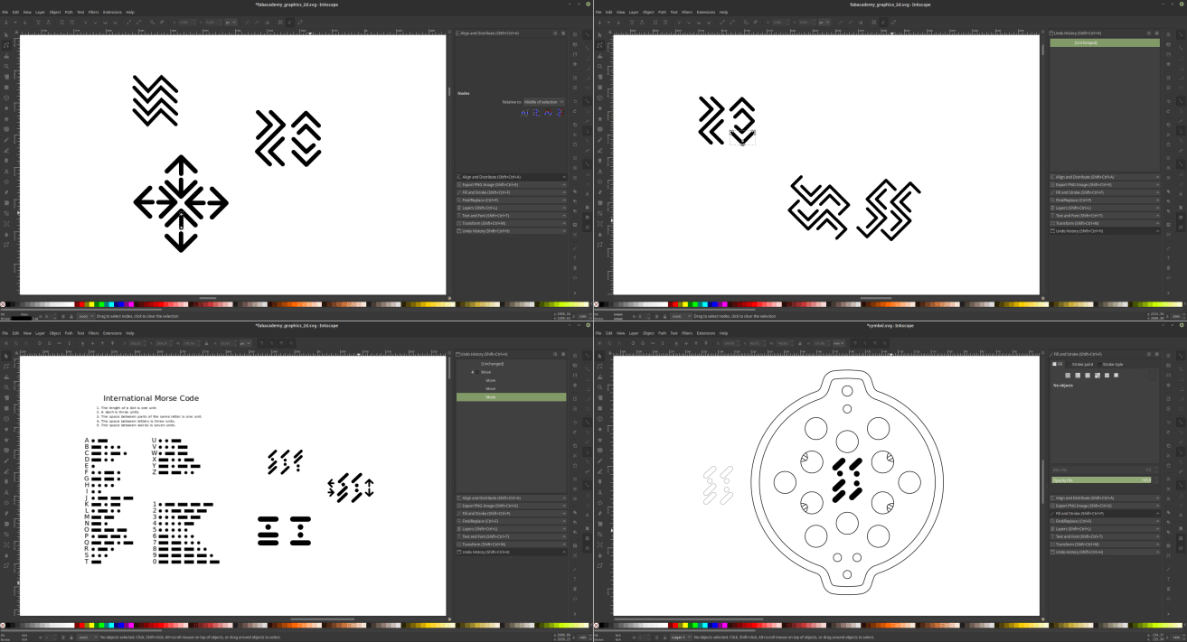
2D - import the vectors in freecad
Once the design was done all I had to do was ti import it back on freecad, turn it into a sketch through the “Draft” workbench and use it as a base for a “pocket” command in my top shell.
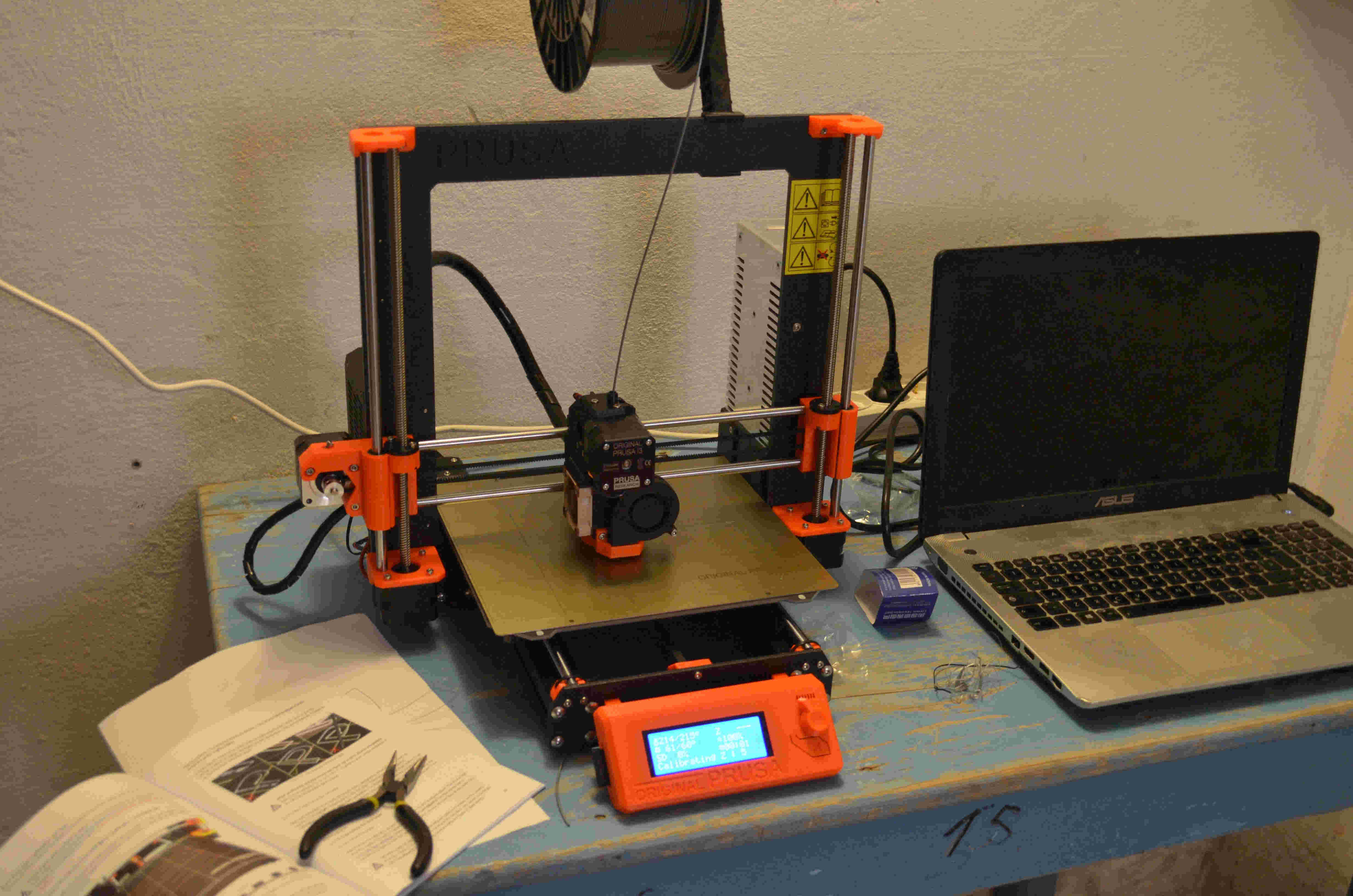
3D printing tests
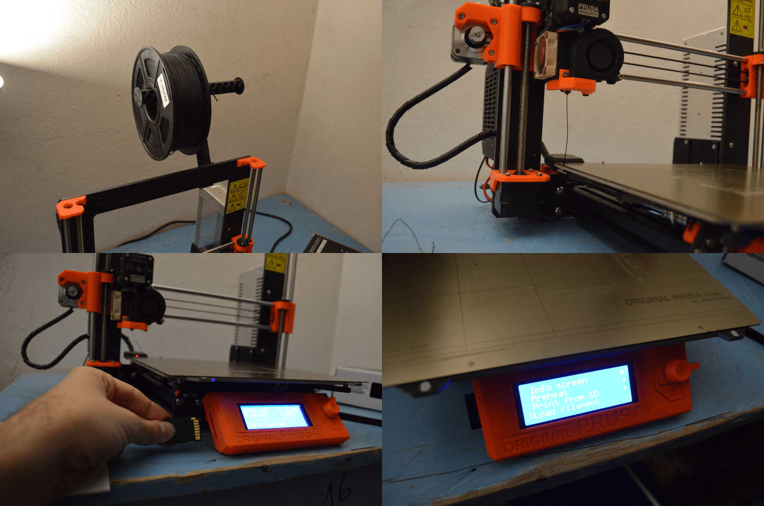
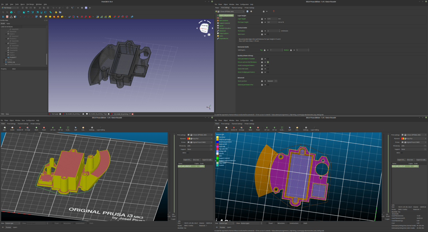
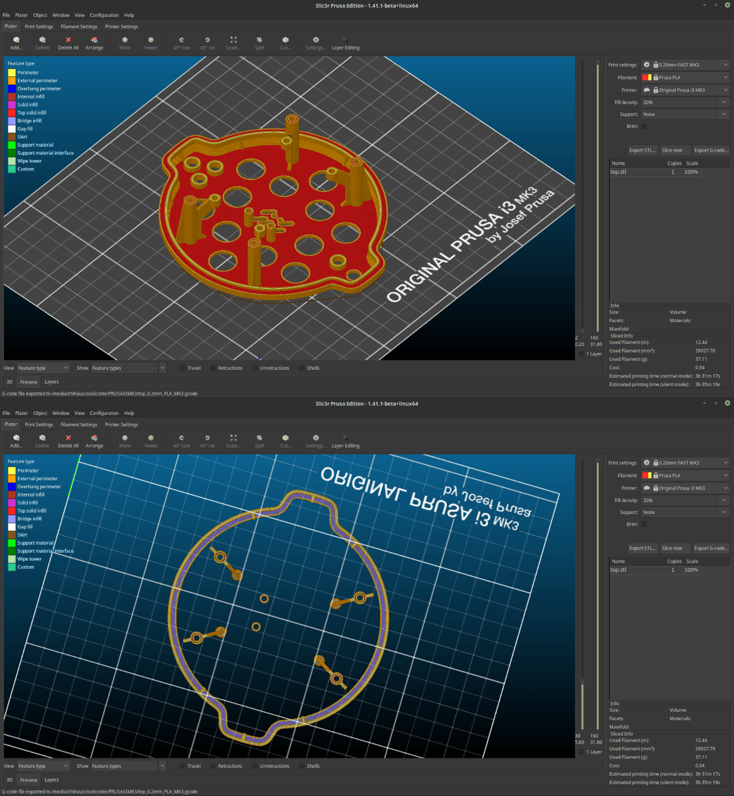
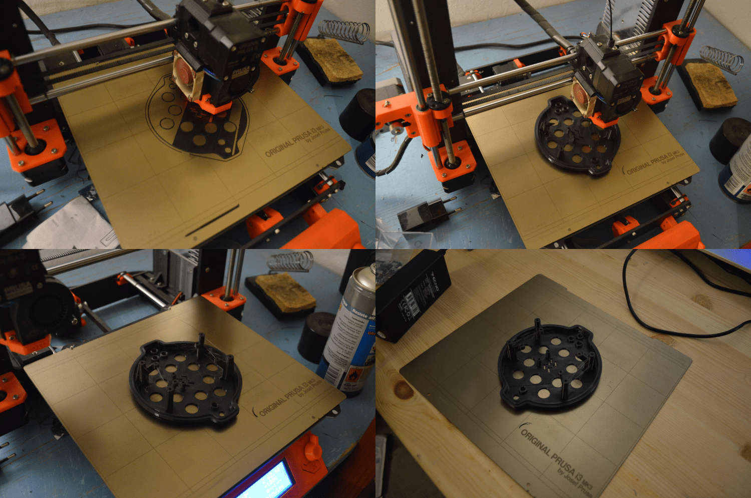
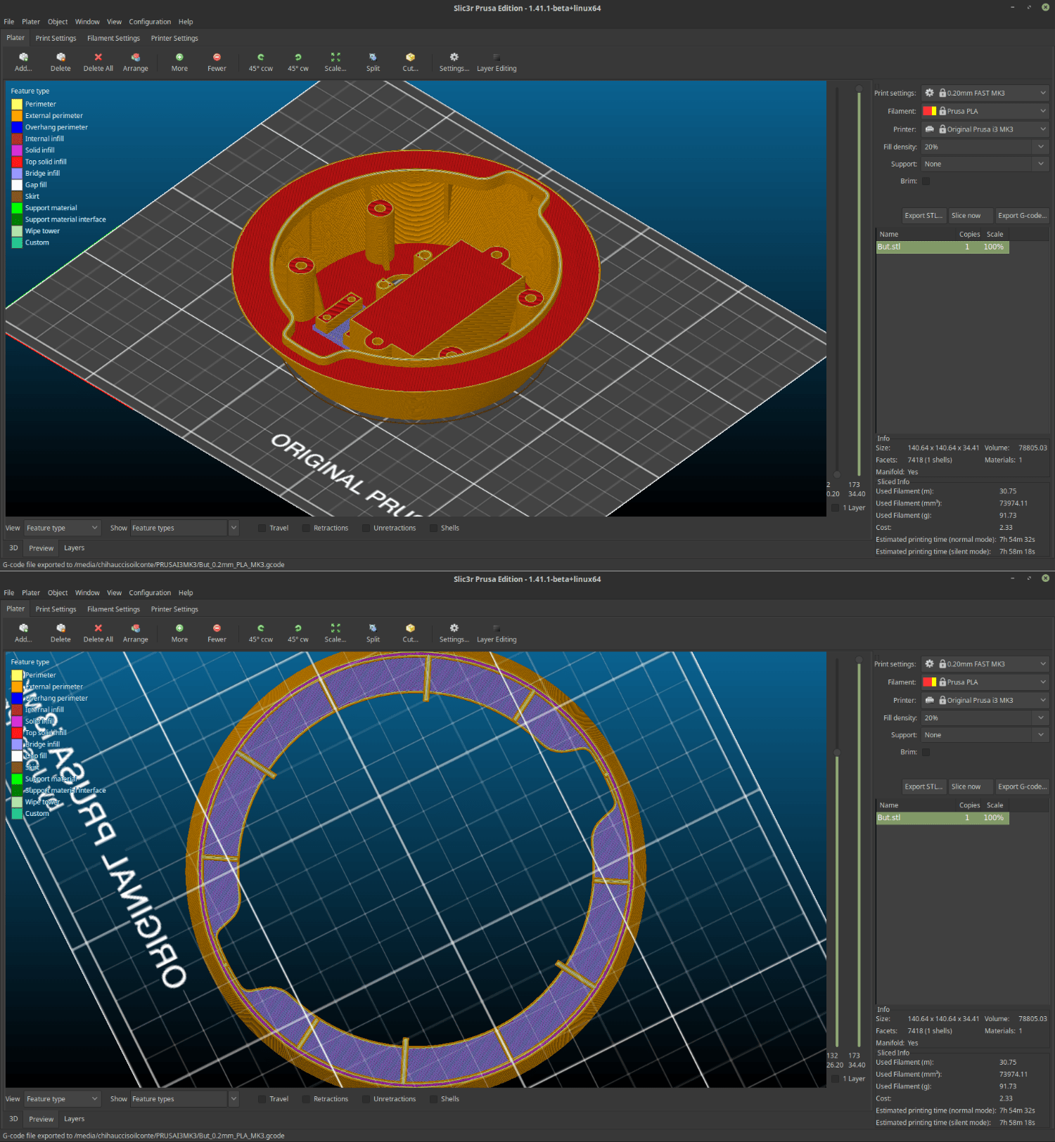
To slice the models I moved to Slicer prusa edition to take care of the postion and the rinting parameters of the machine. The slicer also allows me to test if my assumptions are correct. I can see through the colors in the visualization if my piece includes overhangs and bridging parts. The undercut that will suort the pcb its so inclined that its not even visualised as an overhang part and the slits I designed to suort the overganhing planes did their job because everything its visualises as a bridging plane. Im going to rint this part with a layer thickness of zero.fifteen mm which is a fine quality. Once my model is exorted into my sd cart I can finally approach the mnachine which is a badass prusa i3 mk3. The first thing to do its to lload the filament. in my case pla I preheat the extruder to 215 degrees and I gently accompany the filament inside the extruder so that it takes smoothly the material. Once this is done I insert my SD card containing the gcode I just made with Slic3r. The machine starts to move and it uses his "pinda" sensor to detect the exact position of the building plate. then it starts to build my iece layer after layer... The printing went really well. the piece looks nice and the overhanging surface that will kee the pcb its erfectly smooth. The bridging also went well I must not that dued tothe fact that the perimeter of the surface is circular some of the filament did not stick as lanned anb theres a bit of "spaghetti" in the inner part of the piece. The plane its trong and steady anyway and Im sure the world has seen worse, so, I think I can consider this a success.
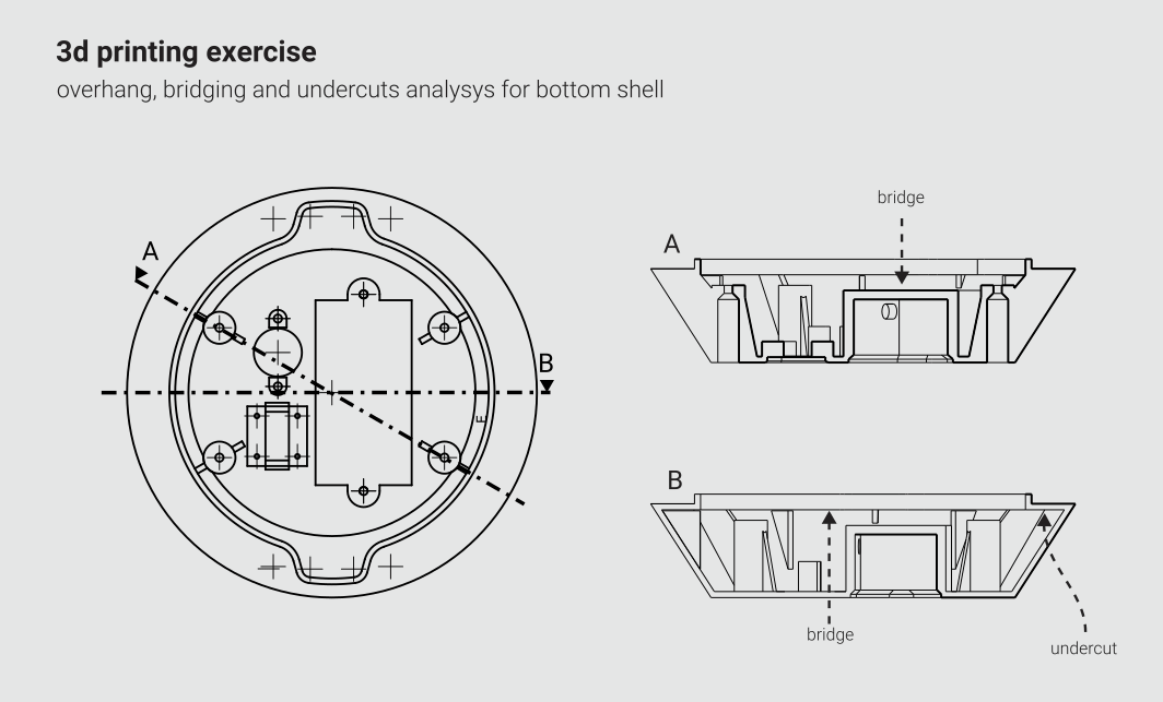
Nest step its going to print a section of the lower shell too wich contains a big bridging area that is the bottom of the battery case + a hole for the MIDI socket and a little frame to contain a tag that I would like to attach to my controller. I feel like mentioning that in this shelll there will be some holes that are not touching the printing surface which could turn in a quite bad thing. to do that I extruded a little plane on to of those trichy elements in this way I turned those overhanging perimeters into a bridging surface that will be handable by the machine and smashed very easily by the screws that willl go inside the comonent I followed the same process I did with the upper shell anb also this print gave me good results (still some little problems in the bridging erimetral area but nothing terrible...)
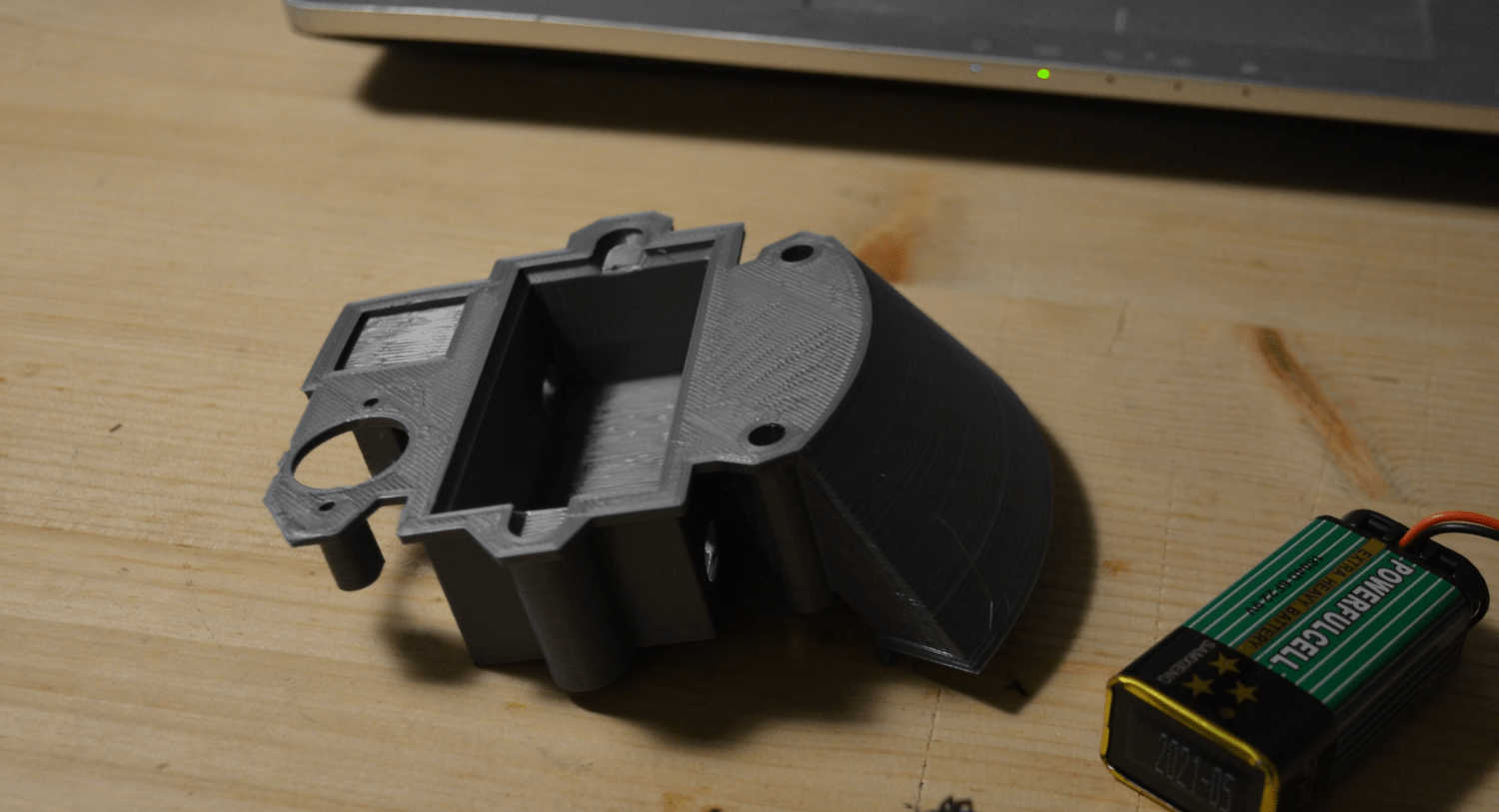
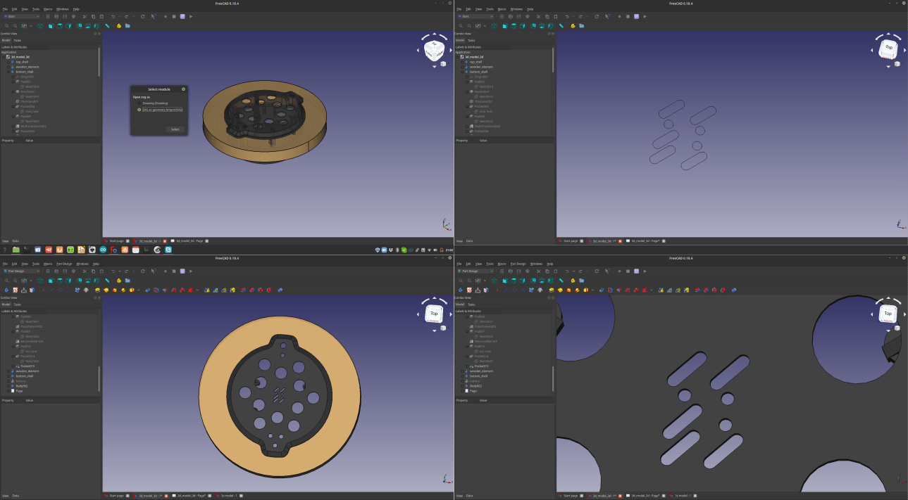
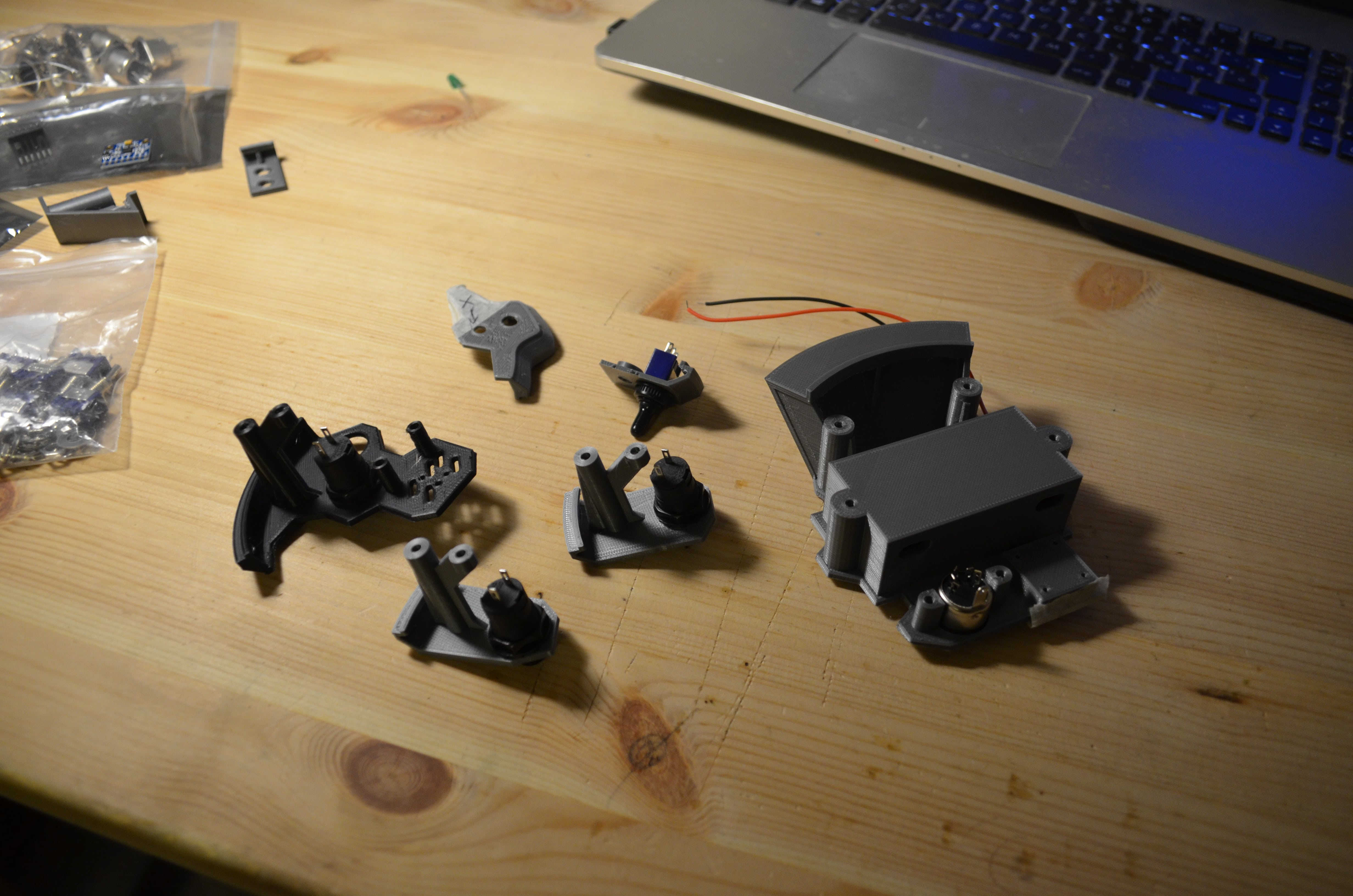
3 –sections of the design to test if the comonents will fit
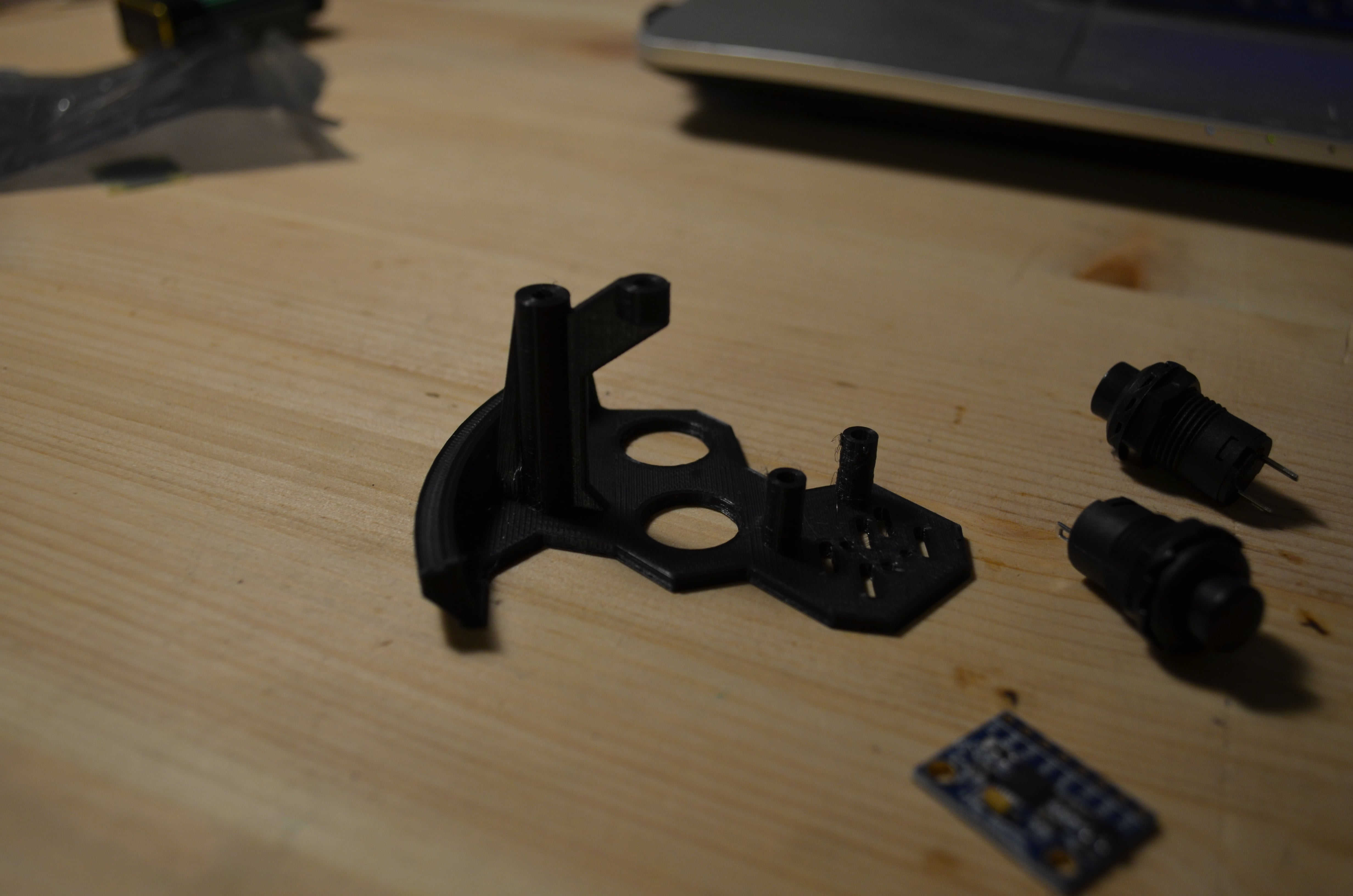
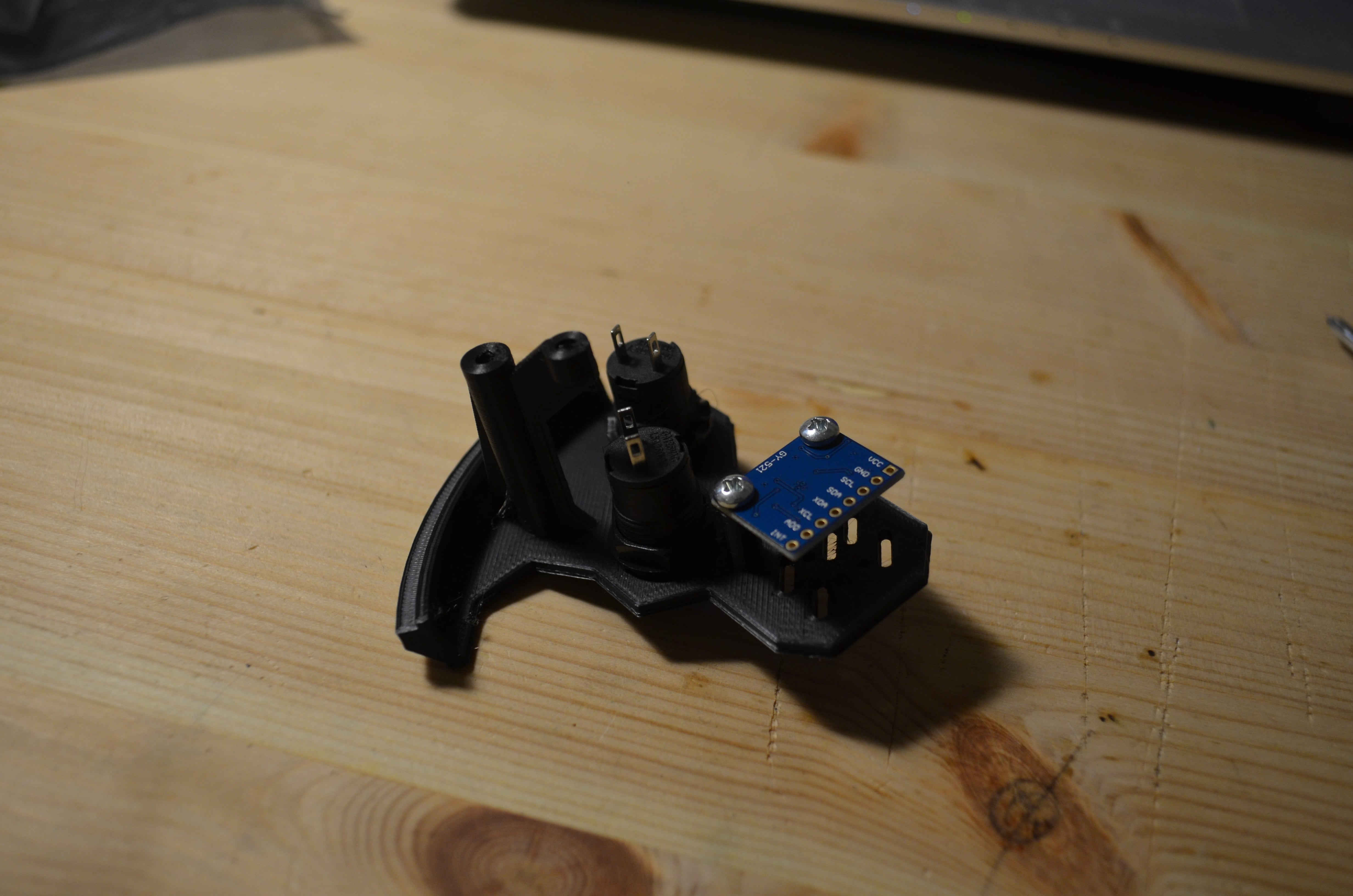
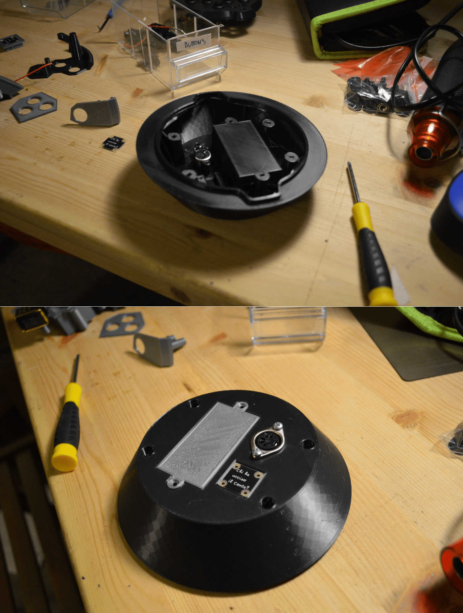
Next test I did was to check if the parts that I’ll need to make my final project work will fit in the parts I designed. So, I took the buttons, the battery, the accelerometer, the MIDI socket and the tag to see if everything worked and the answer was affermative in almost every case eccept for the tag, and (ouch...) the distance between the circuit support and the lower shell. I noticed that this distance was almost zero which will tur into a non-fitting circuit...
So I came back to FreeCAD and fixed those problems and I also made some more STL files to test other components like LEDs and the switch.
After a littke bit of ping-pong I managed to make everything fitat perfectly!
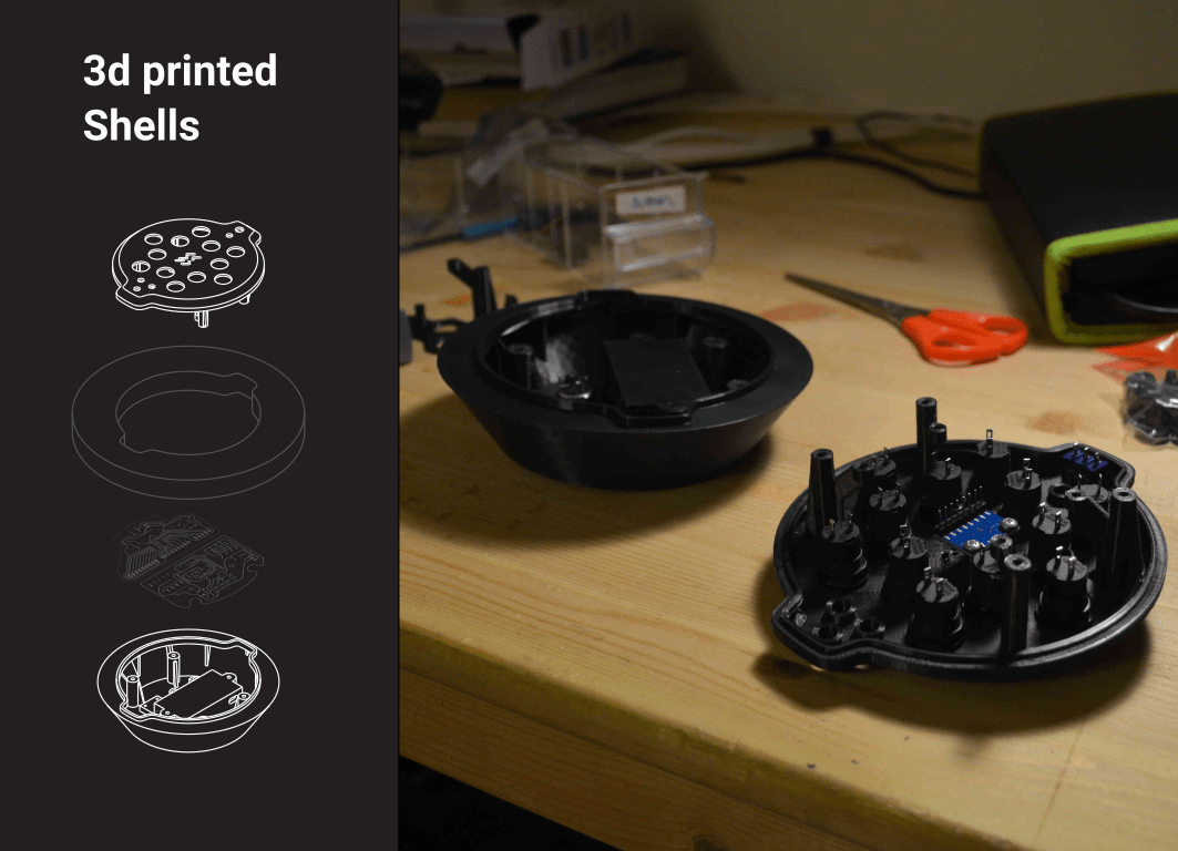
3d print the whole shells
Last art of my assignment was to finally rint the whole parts so I exorted them from freeCAD and printed them comnletely. Since the parts were big I was a little nervous about it but I was also confident in the test I made.
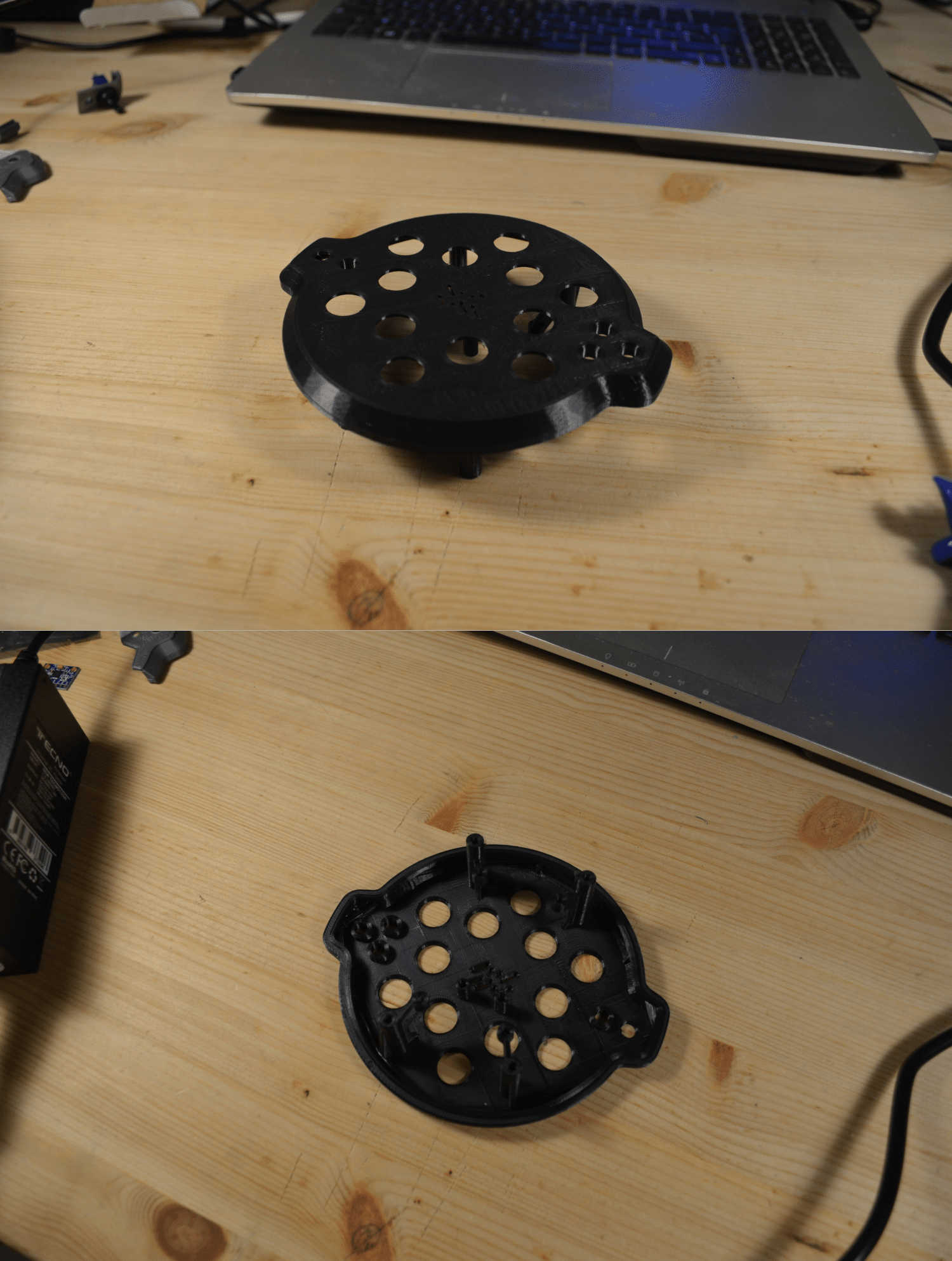
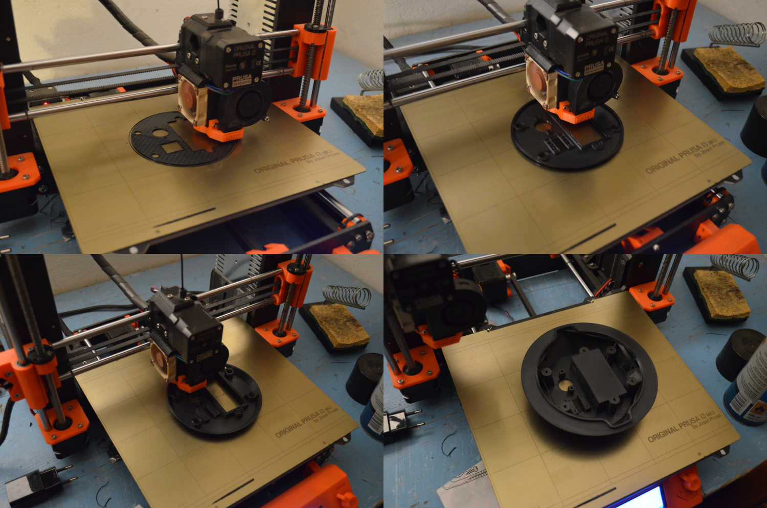
In the upper part there was a little bit of oozing which is a very thin filament that goes all over the part. it is ossible to fix that by just blasting hot air around the piece with a heating gun however this is a symtom of the fact that the ressure of my extruder its too high and that is probably dued to a nozzle that is too close to the printing surface so I re-calibrated the machine and went for the bottom shell which came out perfectly.
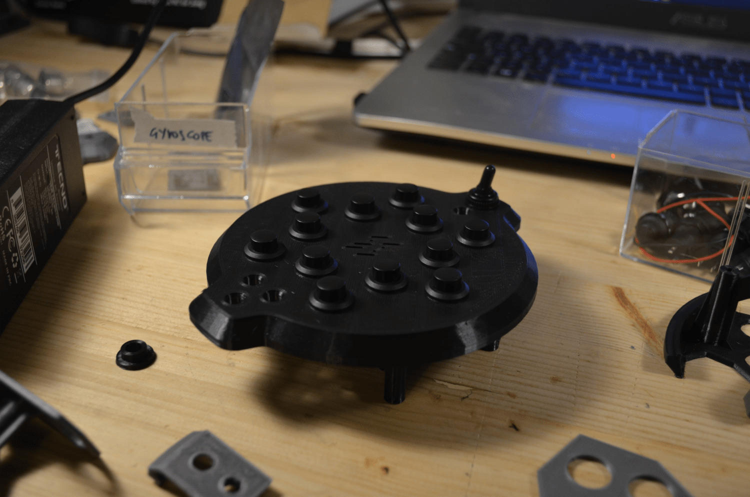
Last thing I did was to place the comonents into my shells ands Im very happy with what I had in my hands at the end of the process.
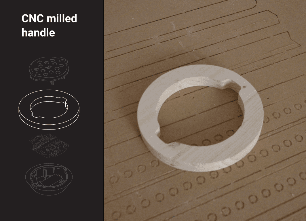
CAM for the middle element (handle)
The wooden element was made with a CNC milling machine.
To generate the gcode and drive the milling machine I use the Path workbench from FreeCAD
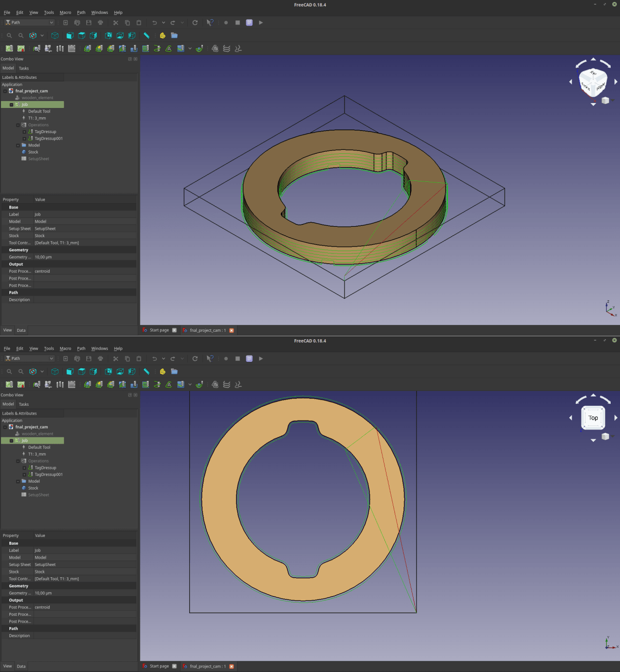
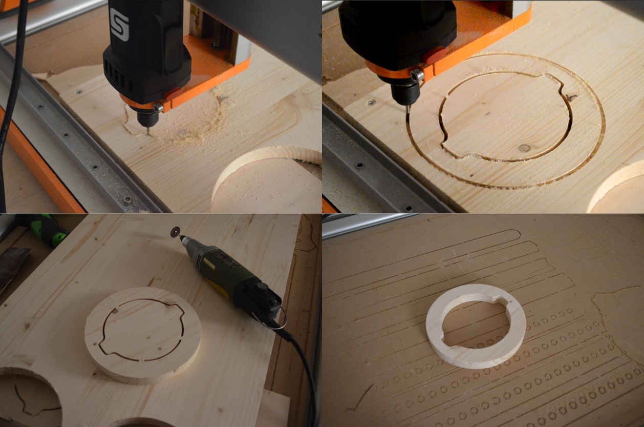
Milling final project wooden element (handle)
The handle of the MIDI controller I'm designing will be will be milled out of a very nice piece of fir wood.
Just like I did for the assignment, I first set up the origin of the milling work, and then I sent the job to the machine, then I removed the tabs with a Proxxon and used some sanding paper to smooth it.
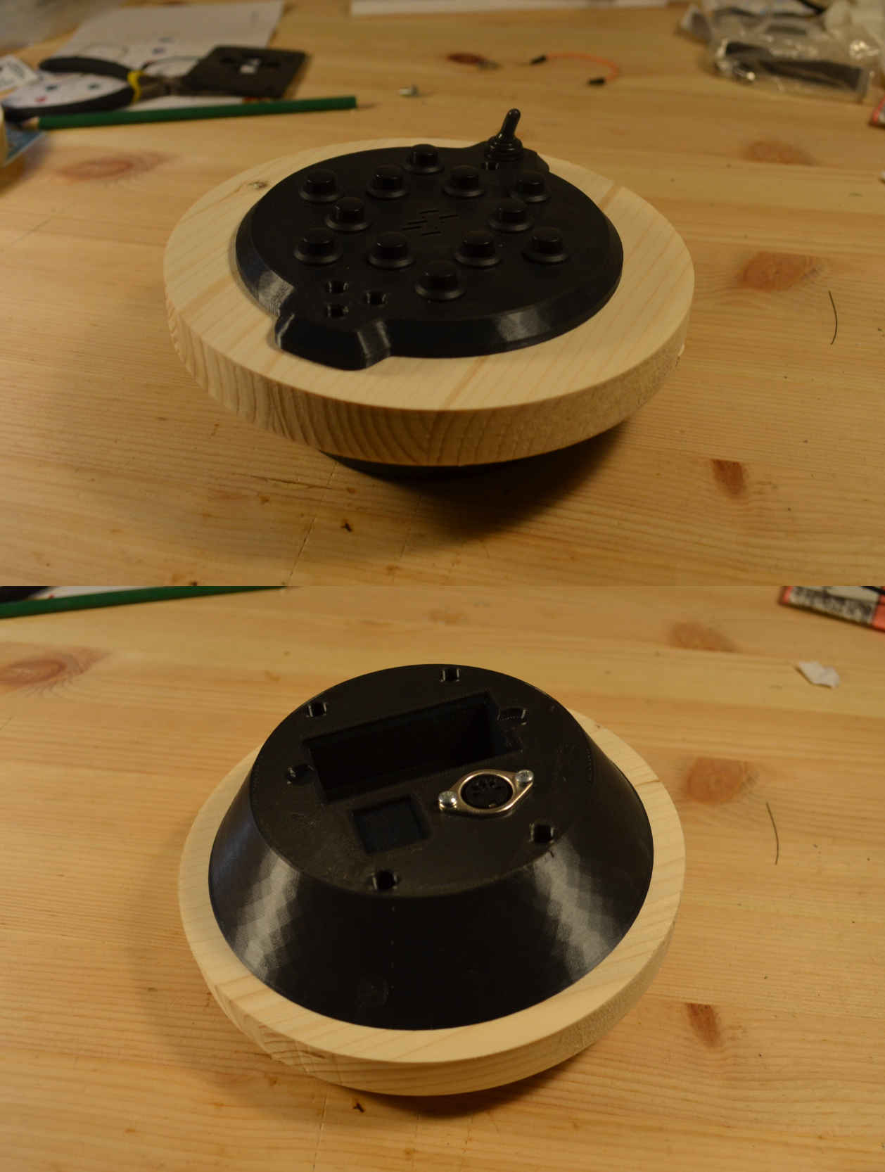
assembly test for final project wooden element
The 3d printed shells perfectly fitted with the wooden element, and once it’s secured with screws it’s very firm and steady. I like very much the combination between the black plastic and the wooden element. I might try to color the wood before applying protective paint on it.
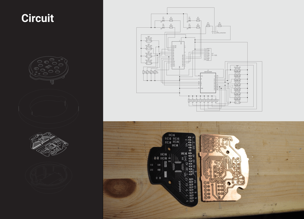
Electronics
The electronics for my final project were also developed during the assignments. In order to work my MIDI controller needs a series of inputs, which are a set a 12 buttons and a gyroscope. As Output devices the controller will have a few LEDS, and of course a MIDI connector to send signals to a sound device.
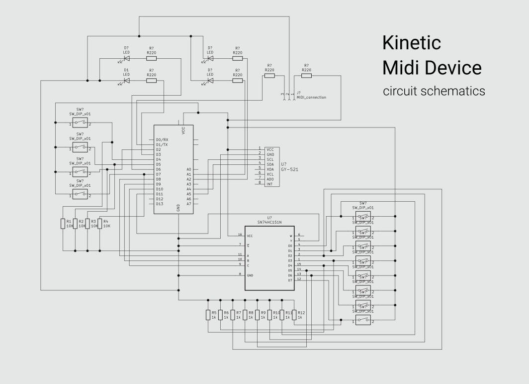
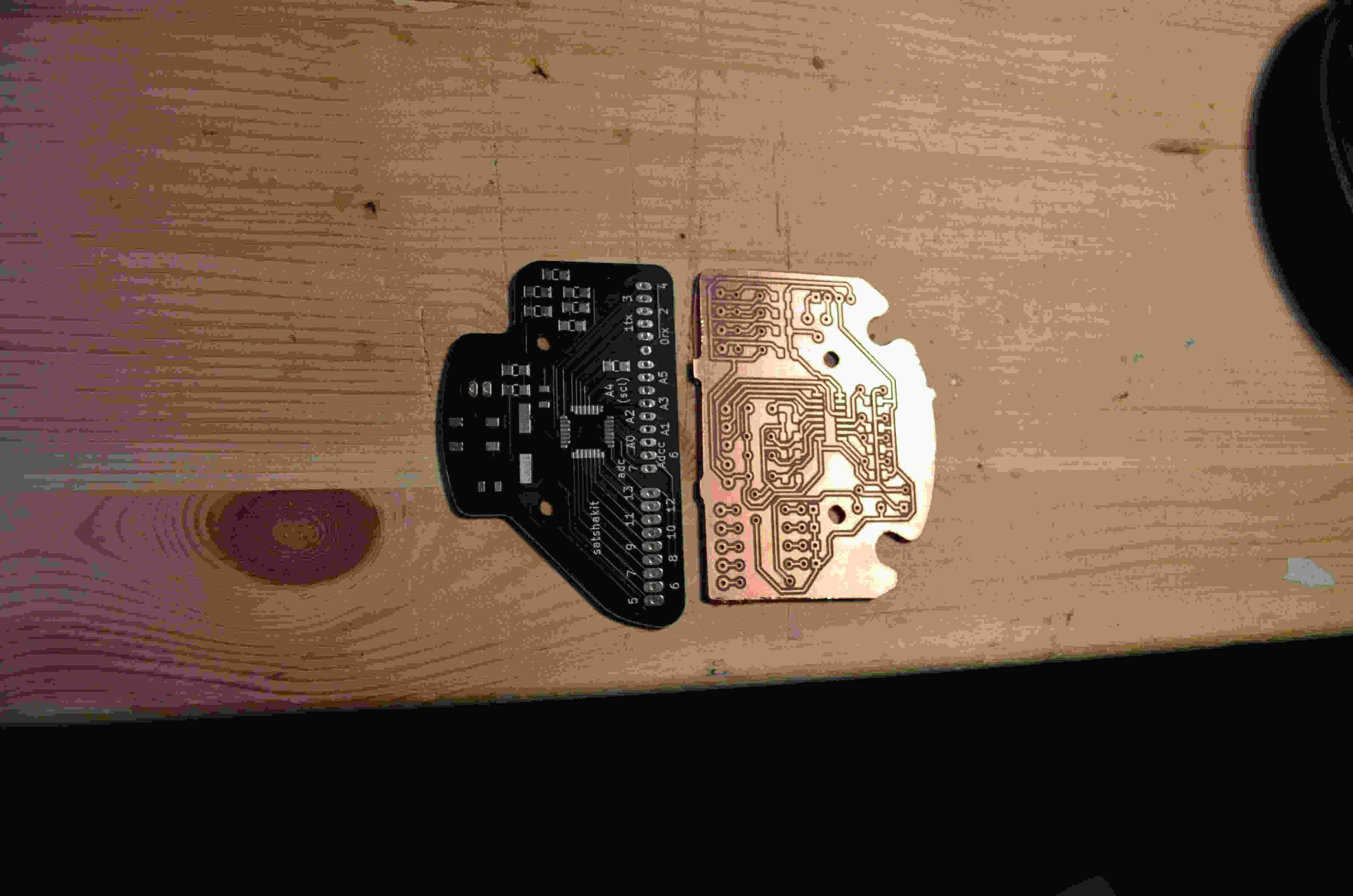
So, the electronics will be made out of a Satchakit and of a PCB containing all the input and output devices.
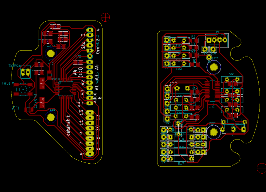
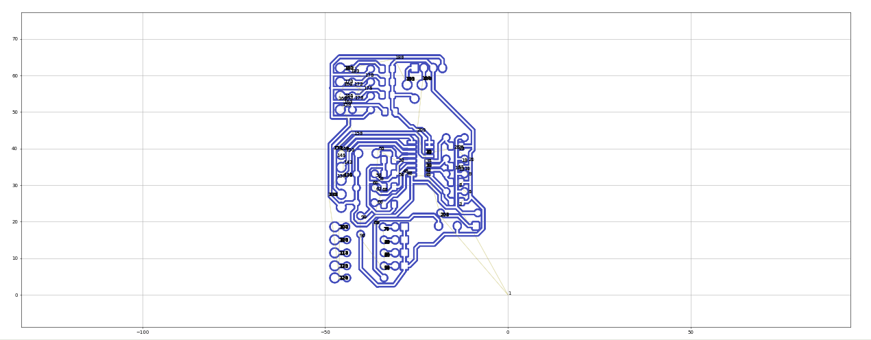
I designed the pcbs as two semi-circular elements that will fit perfectly in the shells previously deigned. To do this I used KiCAD together with the very powerful add on called “Kicad Stepup”, that allows you to design the edge cuts of your PCB using freeCAD tools.
The Satchakit was produced by a manufacturer because at the time we were in the middle of the Covid Lockdown, and I thought it could be a smart thing to commission the production of the device as Neil told us about once.
The input/output PCB was milled, to do that I prepared the gcode using flatcam, and the Stepcraft 2/600 black edition to mill the pcb.
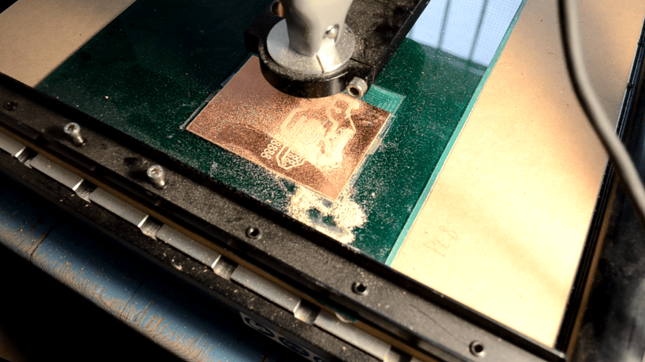

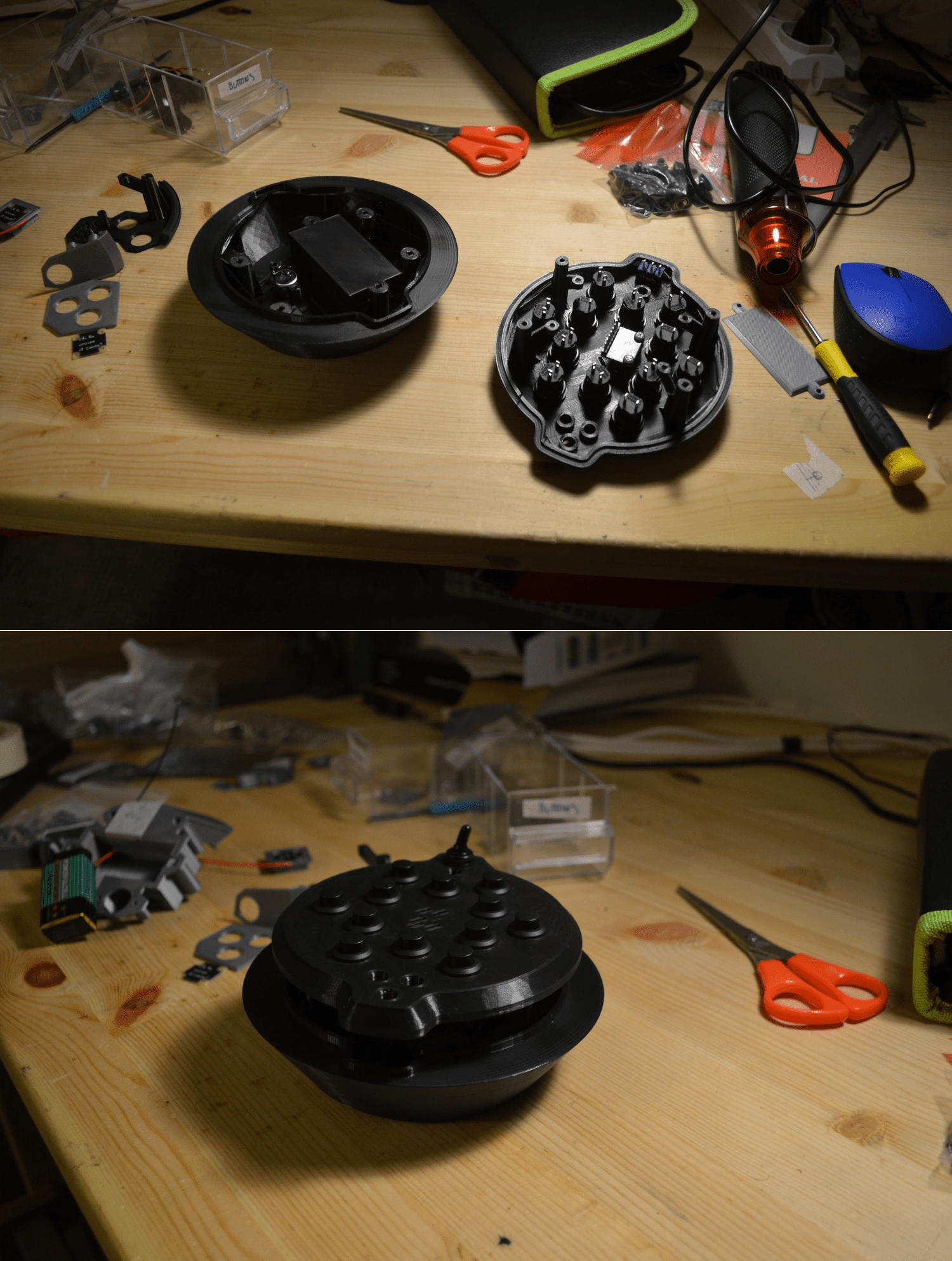
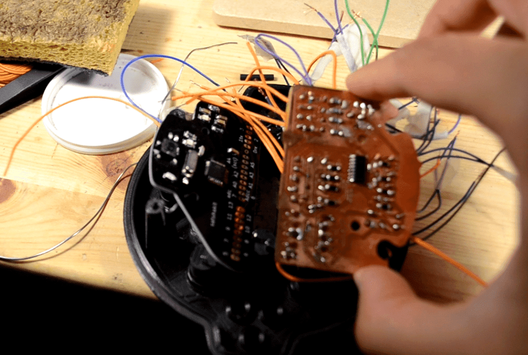
Once this was done I soldered the components on the boards and placed them inside my device.
As usual the soldering process was quite though, and there was a big difference between the one I milled and the one with solder mask.
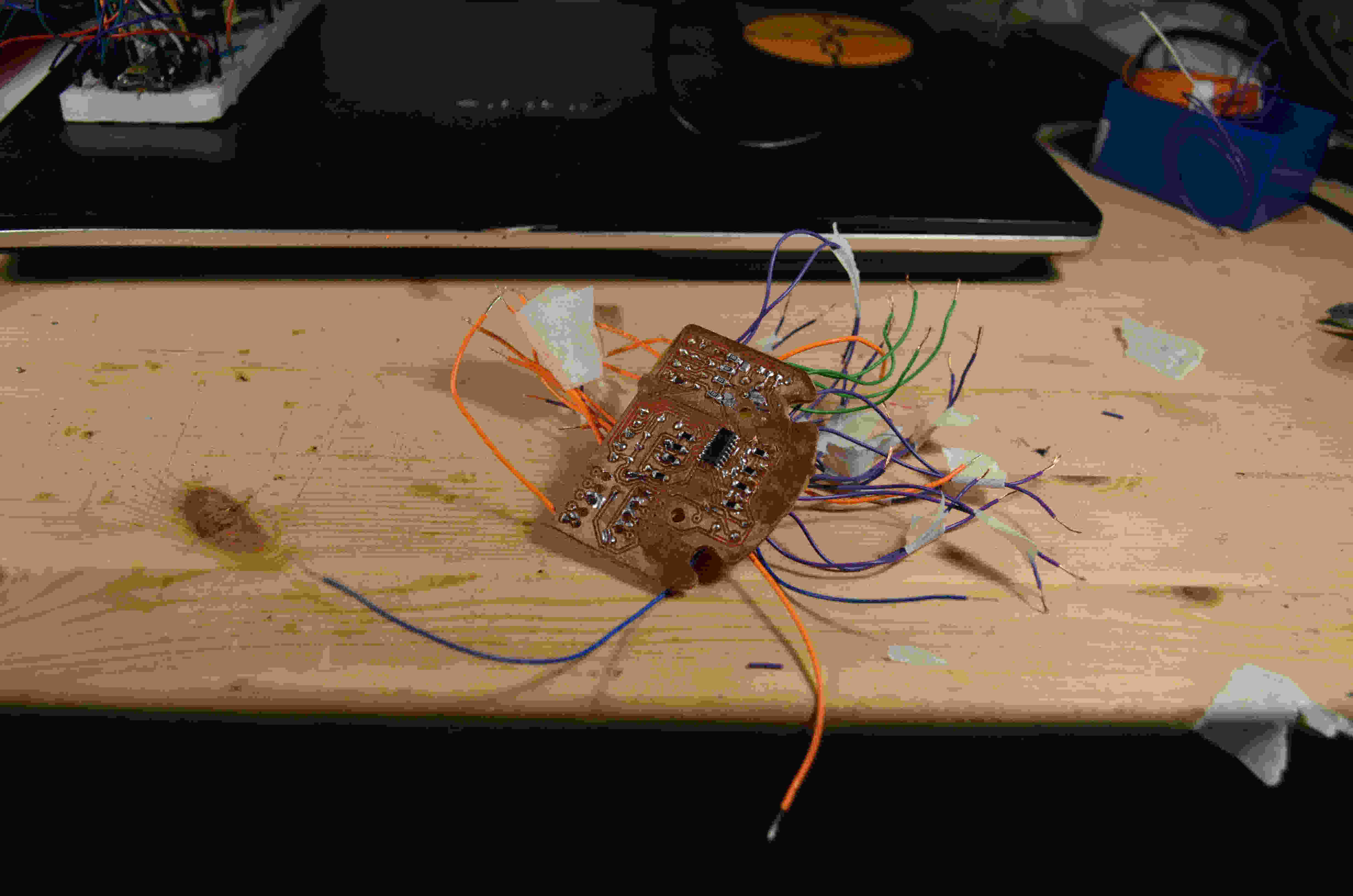
Anyway everything seemed to be acceptable, and so, I uploaded the code using the Arduino IDE.
The code it’s basically the same I made during the output devices week, but I had to change the baud rate to 31250, which is what MIDI needs to communicate.
Use the Device
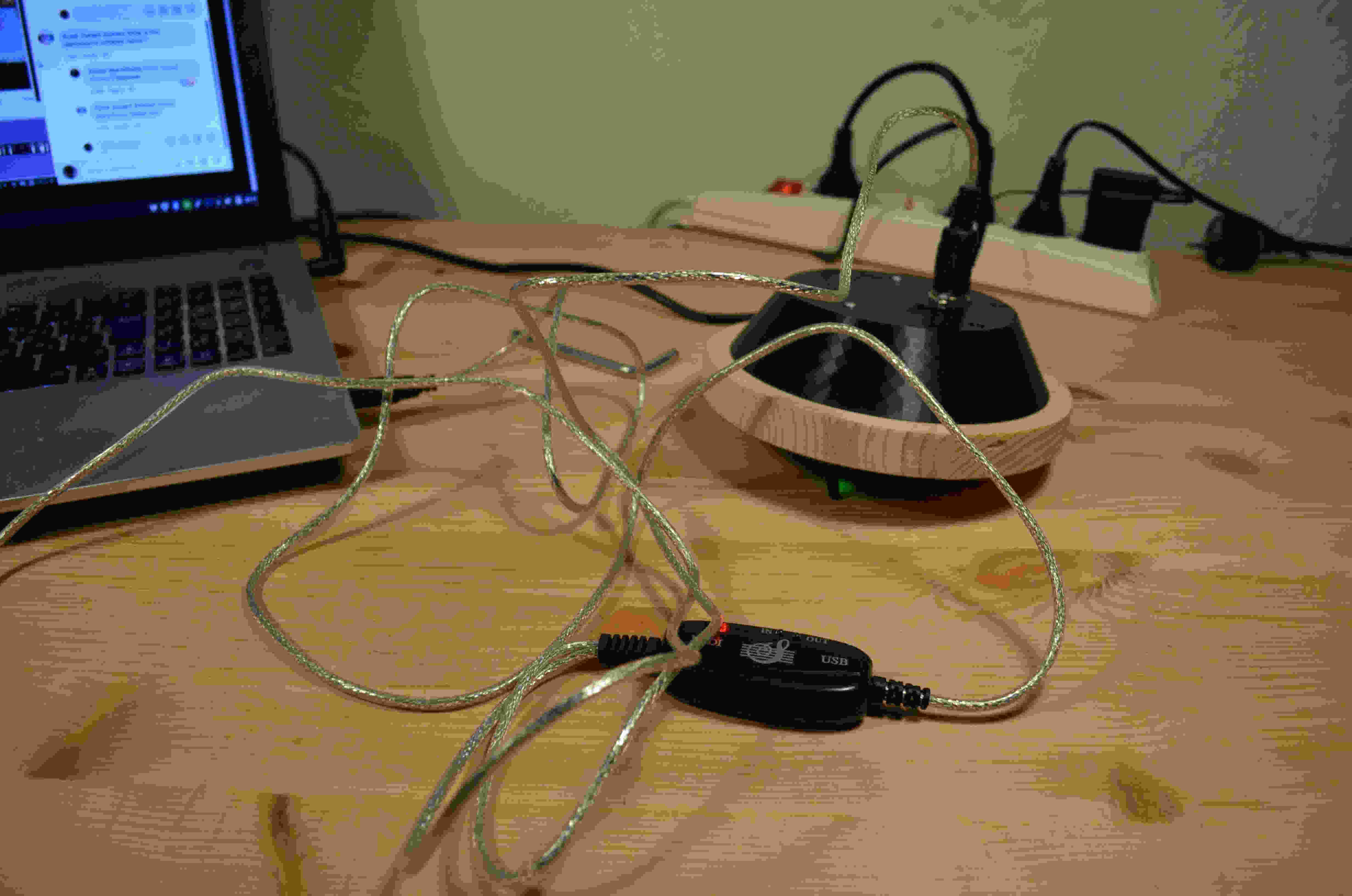
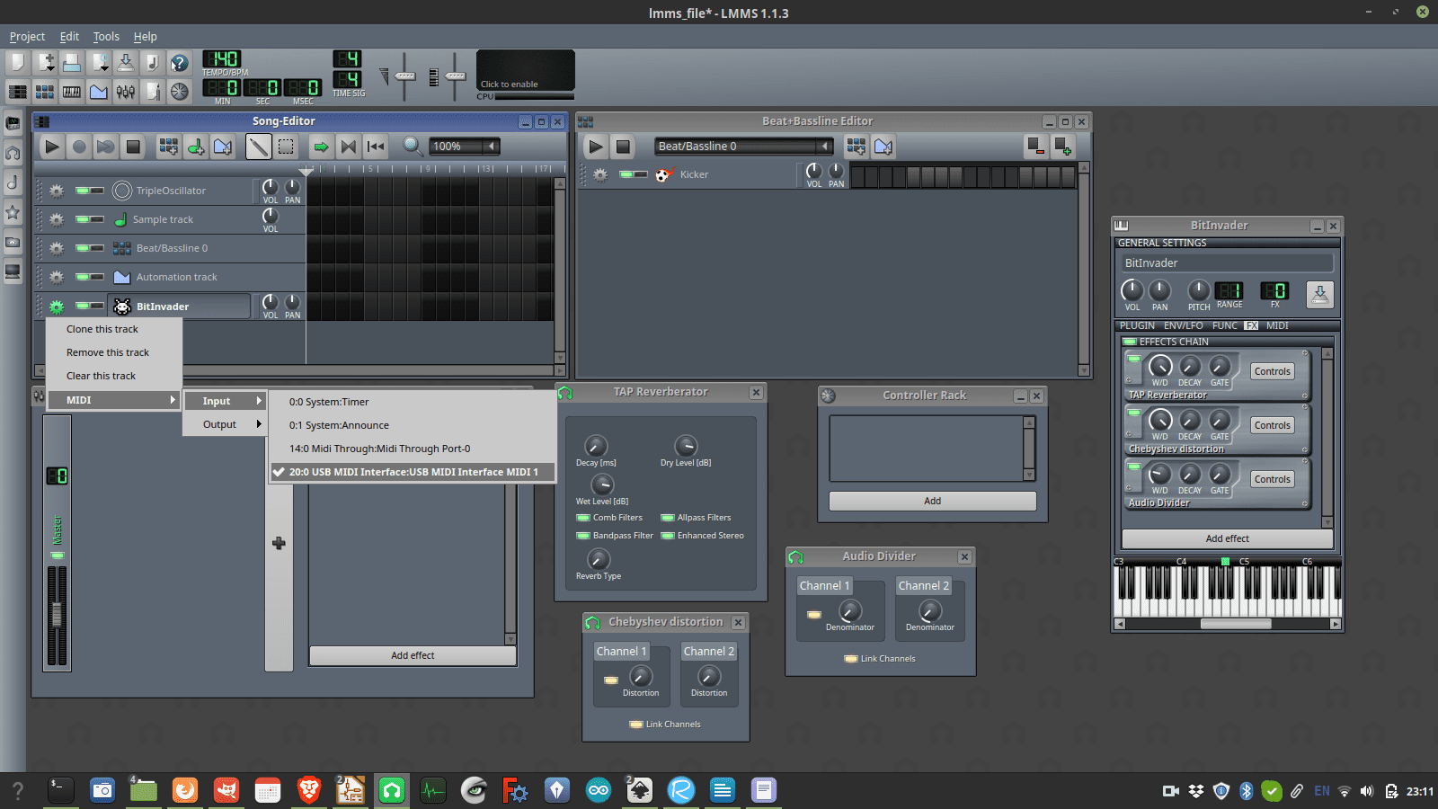
To use the device via usb I got a MIDI usb adaptor, by connecting it to my device and to my PC I was able to connect the controller I made to LMMS, and there we go, I’ve got a working MIDI controller that sends MIDI CC when rotated!
Final remarks
I'm quite happy with the final result I achieved during the program, but for sure there are large margins for improvement, especially in the electronic parts that I milled and soldered. As soon as I'll find the courage to open the device I'll find out why there's something moving inside, tegether with the integration od a voltage regulator and better soldering on my milled PCB.
source files
Here are all the source files for the final project
1 – Top shell STL
2 – Bottom shell STL
3 – Full 3D model - FreeCAD
4 - wooden handle CAM
5 - PCB Satshakit Kicad files
6 - PCB Output devices Kicad files
7 - code with LED + MIDI