5. Electronics production
This week I worked on defining my final project idea and started to getting used to the documentation process.
Grop assignment :
We were asked to test our milling machine properties by milling a test file using different milling bits .The file contains different values of thiknesses, you can see the process by clicking here.
Milling PCB
For the individual assignment, I have worked on Brain’s programmer using “ATtiny45” microcontroller. And bellow is the steps of how i did it.
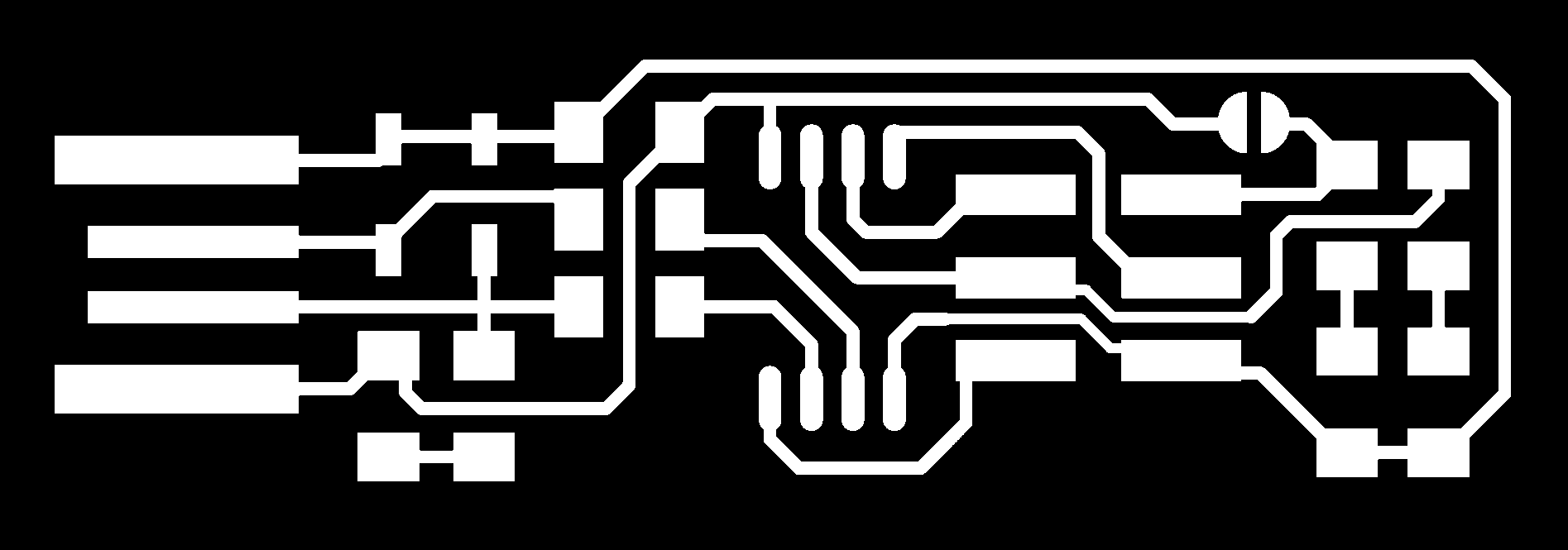
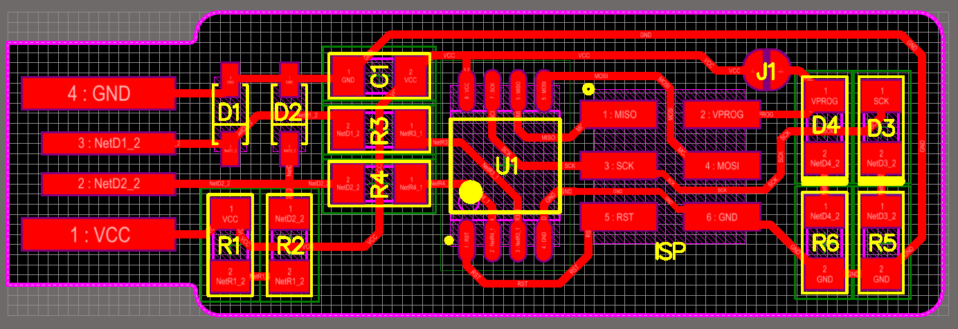
First of all i saved the following images which are the traces and the outline of the circuit.

Next, i uploaded the traces images in “mods” software so i can set up the circuit cutting.
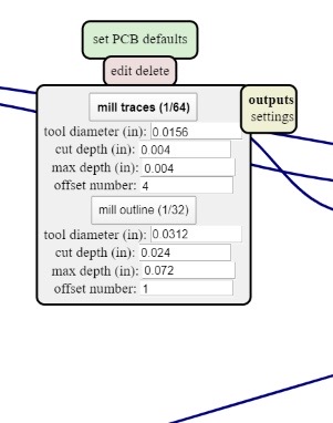 and as you can see above, I choosed the 1/64 since I’m milling the traces, and by defualt the values of the depth and offset apears.
Then i added a new input that will make the machine reads the images as it is. To do that right click in anywere, then “programs” >> “open server program” >> and since I’m using “SRM-20” machine i searched for it amd click “PCB png”
and this is what will apear:
and as you can see above, I choosed the 1/64 since I’m milling the traces, and by defualt the values of the depth and offset apears.
Then i added a new input that will make the machine reads the images as it is. To do that right click in anywere, then “programs” >> “open server program” >> and since I’m using “SRM-20” machine i searched for it amd click “PCB png”
and this is what will apear:
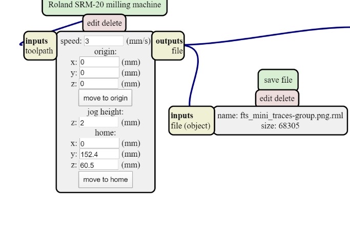 then i connected it with the output, Then press “calculate” the red lines shows the movement of the machine and make sure that it will pass through all the paths of the circuit.
Finally, I saved it as “rml” file.
then i connected it with the output, Then press “calculate” the red lines shows the movement of the machine and make sure that it will pass through all the paths of the circuit.
Finally, I saved it as “rml” file.
Now Its ready to be cut. I placed the ( 1/64 excavator ) and set up tha x,y and z origins,
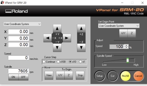 by clicking the arrows of the origins, the excavator will move, the “cursor step” section where you control the speed of the movement while setting it up, then click set origin point x,y and z then cut, delete all the old files and upload the new one, The machine will start cutting and it takes a few minutes.
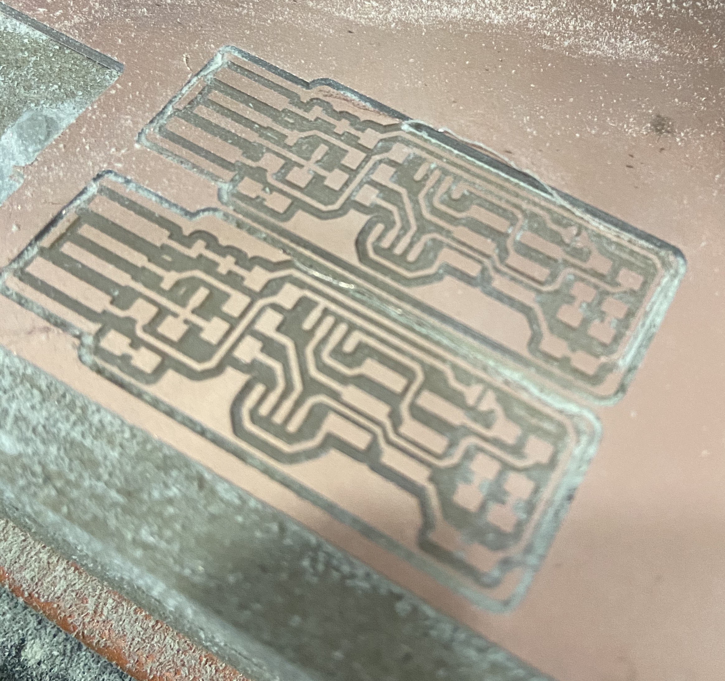
After it finishes cutting the traces, I replaced the 1/64 to the 1/32 which it excavate deeper to cut the outline, then i re-placed the z origin, and return the x and y origins to it first place.
by clicking the arrows of the origins, the excavator will move, the “cursor step” section where you control the speed of the movement while setting it up, then click set origin point x,y and z then cut, delete all the old files and upload the new one, The machine will start cutting and it takes a few minutes.
After it finishes cutting the traces, I replaced the 1/64 to the 1/32 which it excavate deeper to cut the outline, then i re-placed the z origin, and return the x and y origins to it first place.
Soldering the component
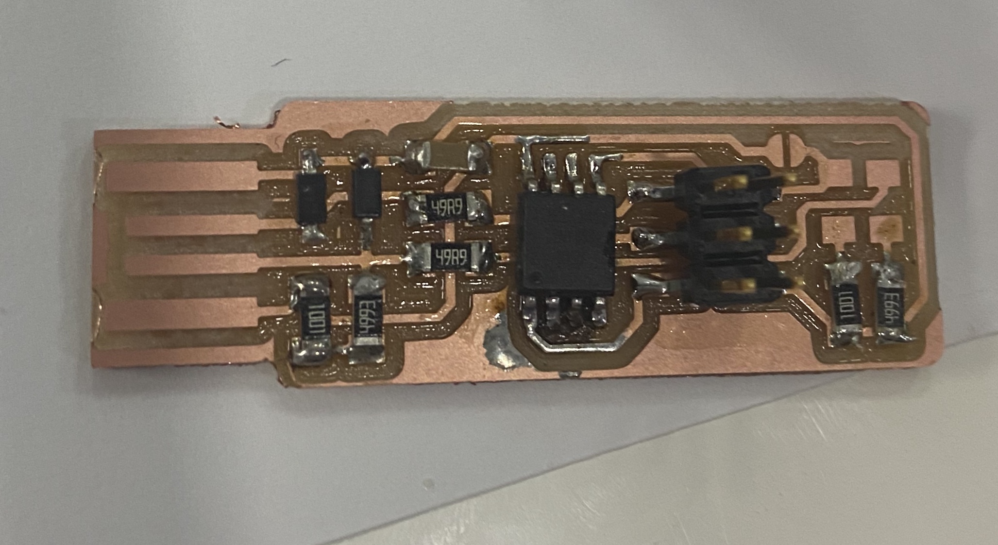
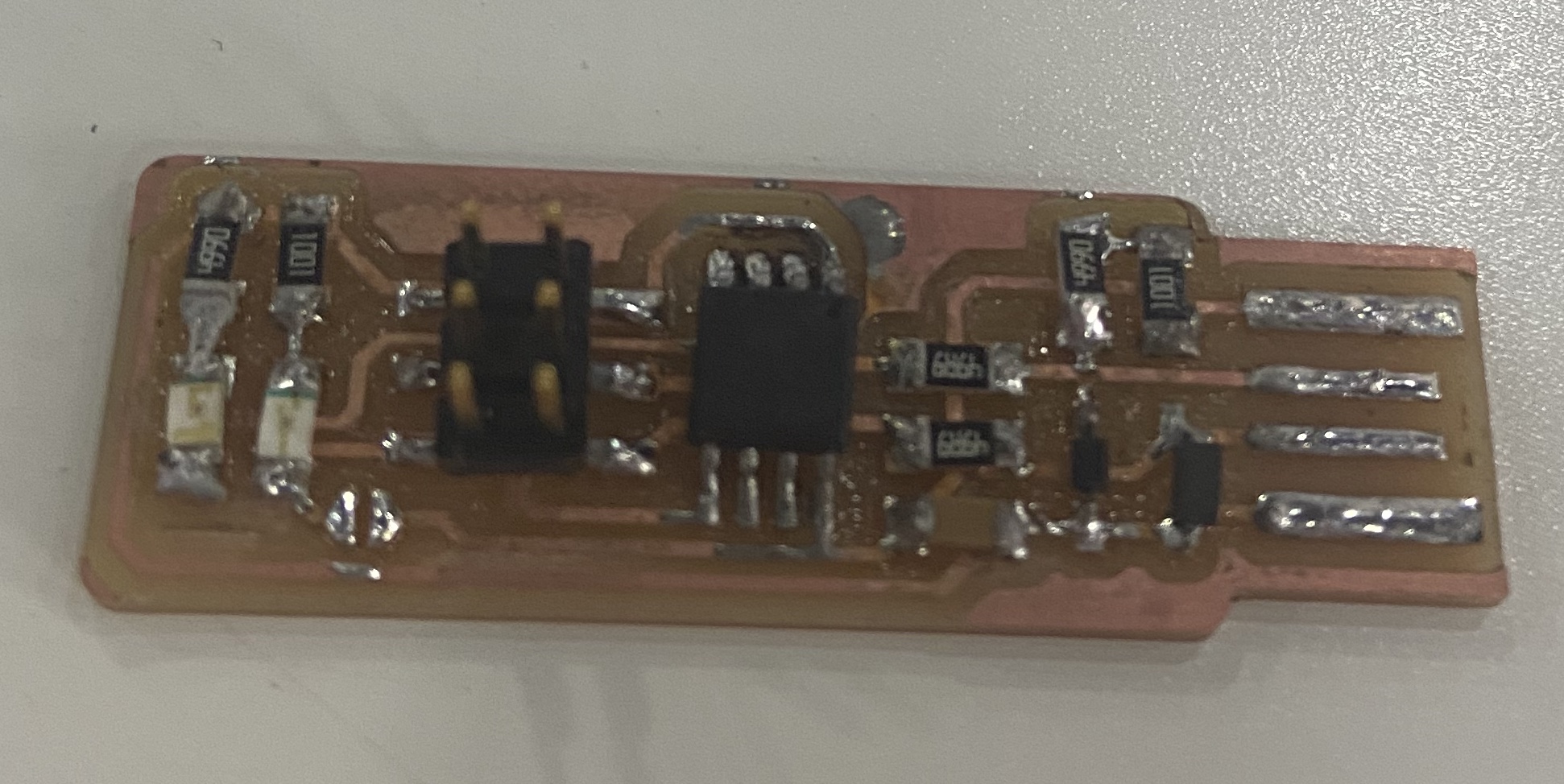
I Obtained the components that needed:
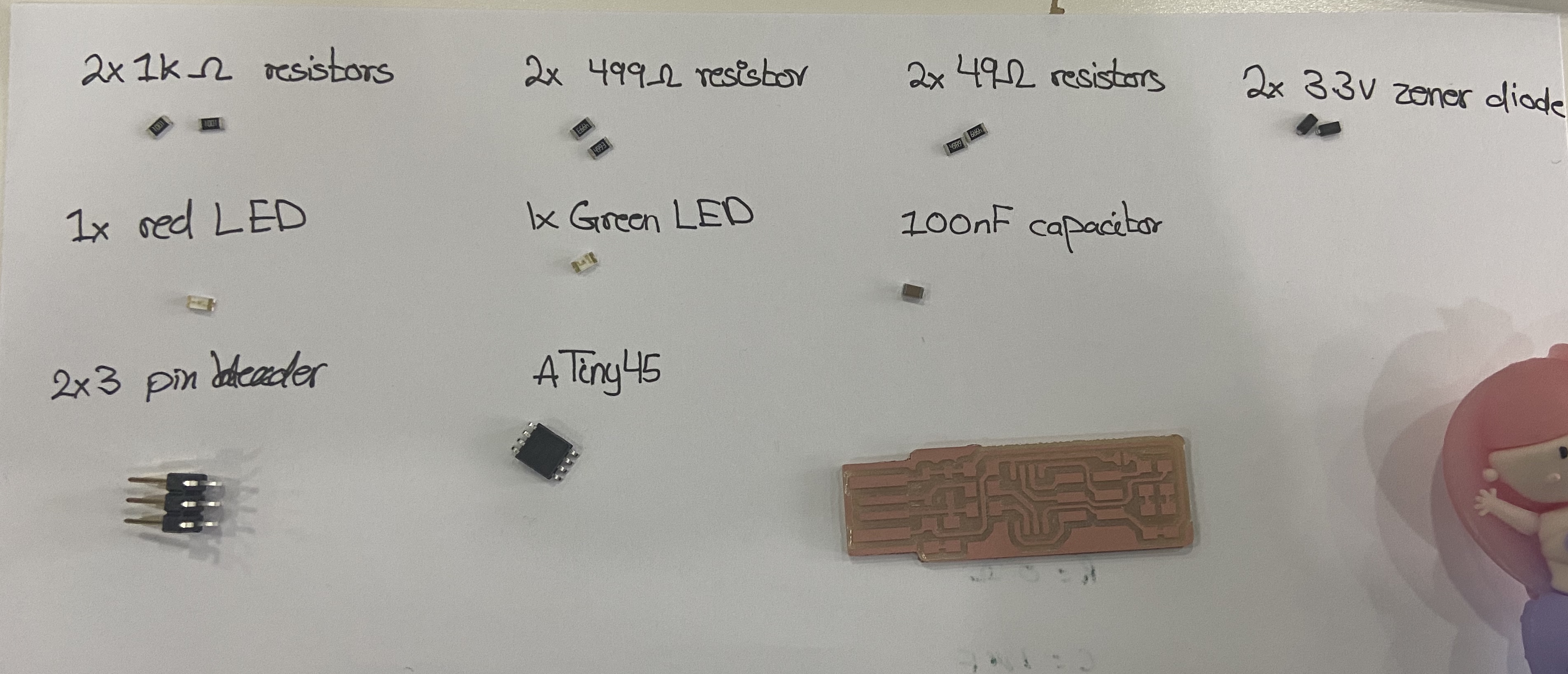
and uses the below image as a refrence;
Then I began soldering the middle components first and end up with the components that in the edges.
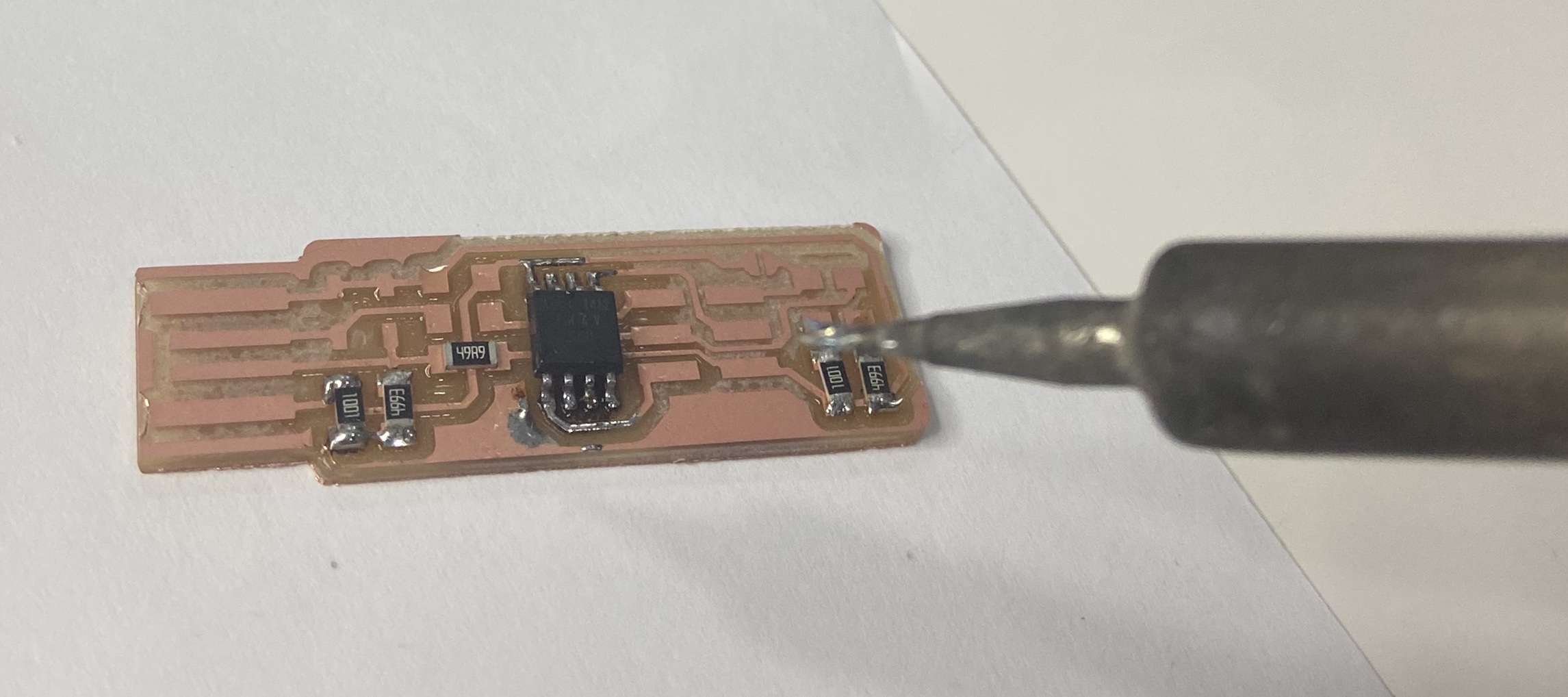
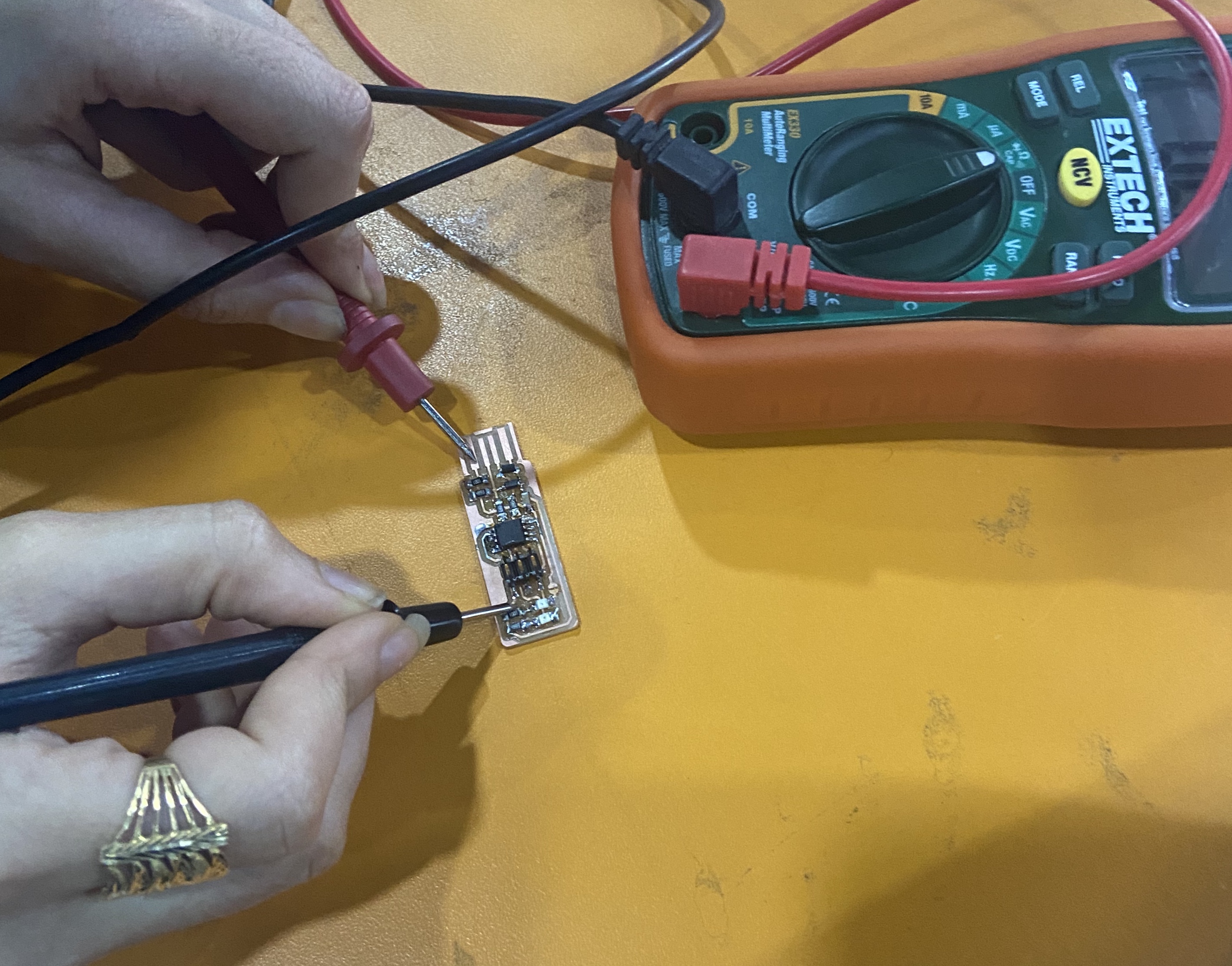
After soldering all the components, i did the continuesly test with the voltmeter to make sure that there is no short in the circuit.
Next, I removed the end edge with a knife since its extra.

Programming
For programming, I followed Brain’s steps. First, Dowmload CrossPack Since I’m using MacOS.
Then download firmware source code
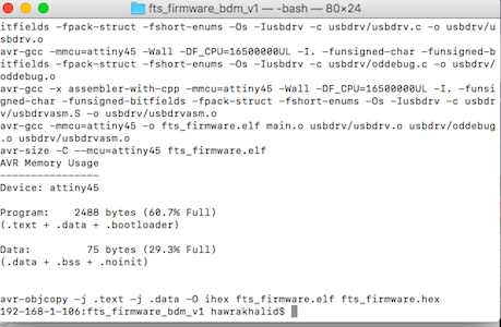
Now open the terminal and cd into the source code directory, then run the command “make”.
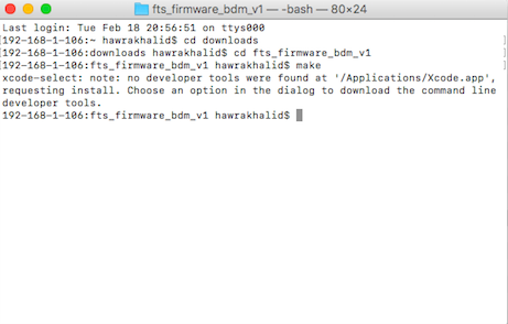 this opened a “hex” file which will get programmed onto our micro-controller.

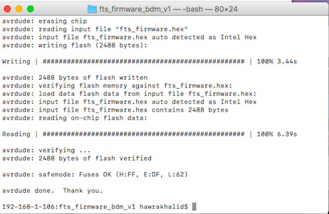
After that i connect my programmer with other one using USB wire. Then back to the terminal run the following commands: - make flash
 Then
Then
- make fuses
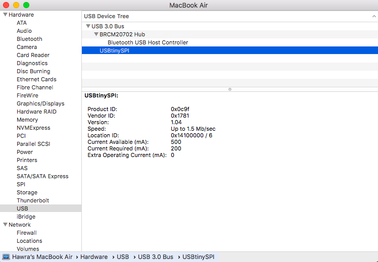
Then, to make sure that the computer recognized by USB go to “apple menu” >> “about this mac” >> “system report” >> “USB”
 and as you can see above there is no “ATtiny” so my pc did not recognize it.
So i tried several things, I changed the usb cables, re-cecked the connection paths over and over , I soldered the USB contacts
and as you can see above there is no “ATtiny” so my pc did not recognize it.
So i tried several things, I changed the usb cables, re-cecked the connection paths over and over , I soldered the USB contacts
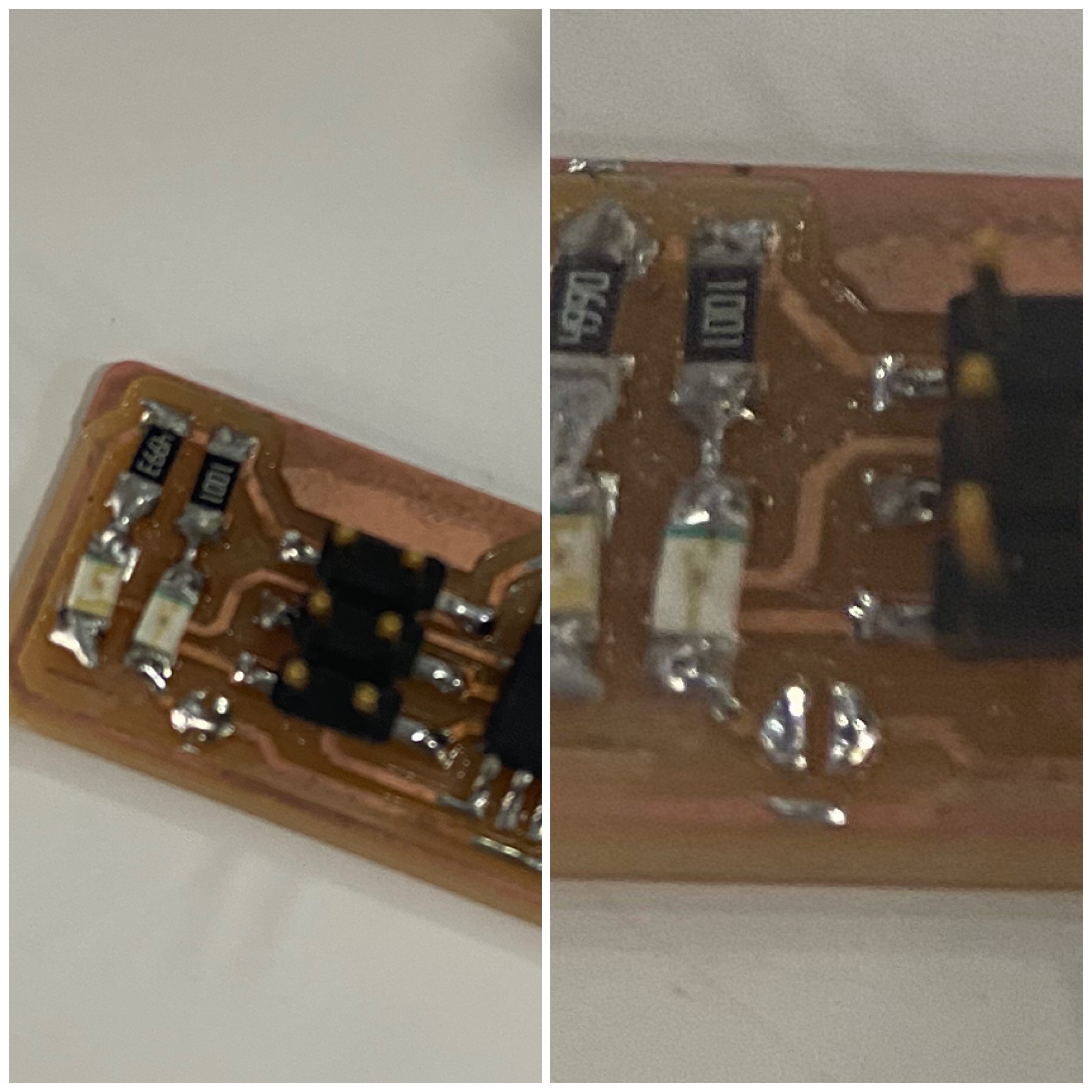
 then I checked the values of the resisters and it turns that i obtain a different value of the 499 ohm resister, so i immedediately changed them to the correct value.
Then I checked again but still it did not apear, so i re program it from terminal then check again and still not apearing, so I thought that the zener diodes burned when i used the wrong resistors , so i replaced them with other new ones, tried to do it with other computers and unfortunately it did not work either :(
I took a digital USB microscope and check the connection with the voltmeter again, the connection was ok, but i noticed that the solder quality is not that well
then I checked the values of the resisters and it turns that i obtain a different value of the 499 ohm resister, so i immedediately changed them to the correct value.
Then I checked again but still it did not apear, so i re program it from terminal then check again and still not apearing, so I thought that the zener diodes burned when i used the wrong resistors , so i replaced them with other new ones, tried to do it with other computers and unfortunately it did not work either :(
I took a digital USB microscope and check the connection with the voltmeter again, the connection was ok, but i noticed that the solder quality is not that well
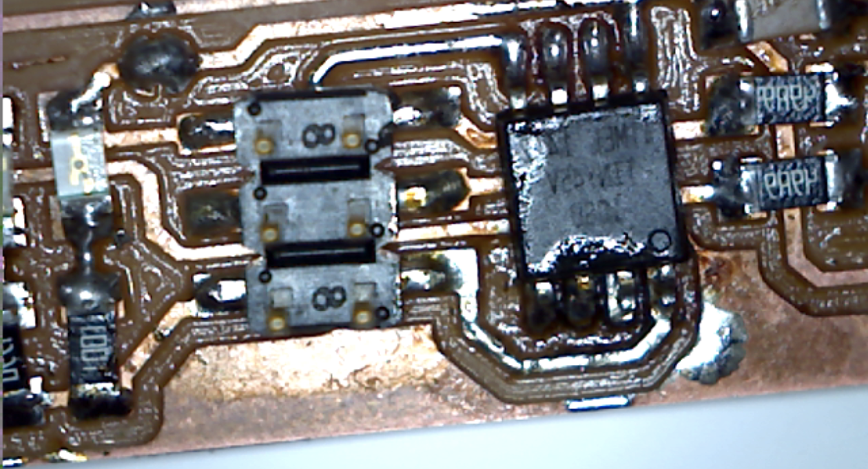 I re solder it and make it shiny as much as i can, and then finally it apeared in my pc!
For the final steps, i onnect my programmer with the other one, then back to the terminal again I run “make rstdisbl” This does the same thing as the make fuses command, but this time it’s going to include that reset disable bit as well.
and finally i desoldered the bridge and now its ready