Output devices (WEEK 12)
Individual Assignment:
- Add an output device to a microcontroller board you've designed, and program it to do something
Group Assignment:
- Measure the power consumption of an output device
IMPORTANT NOTE : ALL OF MY IMAGES ARE POP UP IMAGES , IF YOU HAVE ANY PROBLEM READINGS THOSE IMAGES , PLEASE CLICK ON THEM AND THEY WILL ENLARGE AUTOMATICALLY AND YOU CAN READ THEM EASILY
Tinkercad
Tinkercad Circuit is a free, online Circuit Designing tool that runs in a web browser, known for its simplicity and ease of use . and is very usefull to design and simulate many components.
If you want to try it out you go to there official website by clicking on this link
Our purpose behind using tinkercad was that , during this week we were in a Lockdown due to COVID 19 pandamic and due to which we were not able to work on any of the physical stuf , so rather then wasting
                                                 time our Mentor Neil suggested that we should use tinkercad as it is a virtual platfrorm where we can simulte whole circuit and all the components as well , plus we can upload real code and check how its work and when we get back to lab we will , directly starts working with our PCB and output devices
Please go through this video before getting started
1. DC motor
I have used Arduino to move DC MOTOR to make some using tinker cad circuit and stimulated them
                                            void setup()
                                          {
                                            pinMode(6, OUTPUT);
                                            pinMode(5, OUTPUT);
                                            pinMode(4, OUTPUT);
                                            pinMode(3, OUTPUT);
                                          }

                                          void loop()
                                          {
                                          digitalWrite(6 ,HIGH);
                                          digitalWrite(5 ,LOW);
                                          digitalWrite(4 ,HIGH);
                                          digitalWrite(3 ,LOW);
                                            delay(1000);
                                          }
you can use this code by just clicking and copying it
2. Making song through Piezo
I have used Piezo to make some sound using tinker cad circuit and simulted that
3. Neo pixel LED
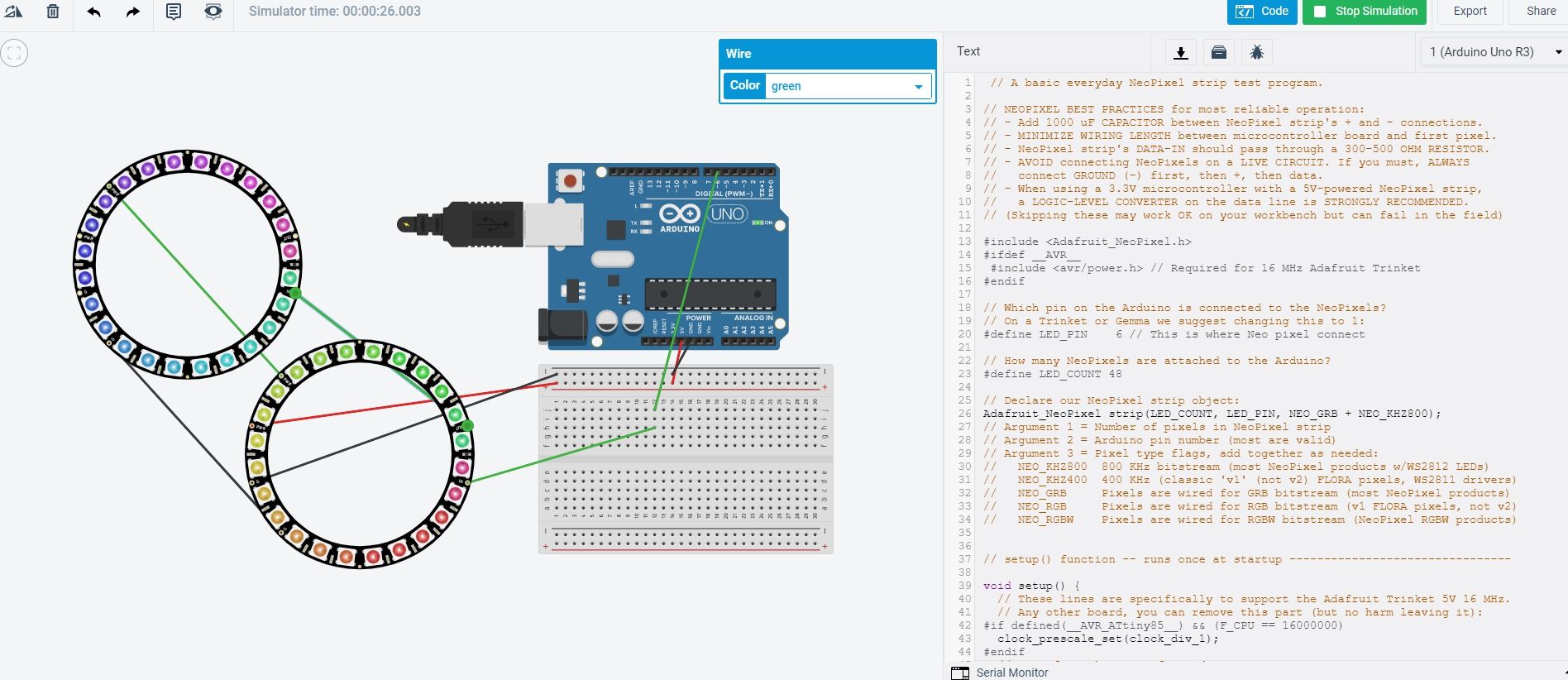
This code was taken fron Adafruit library for NEO PIXEL and I then edited it according to my mood.
                                          // A basic everyday NeoPixel strip test program.

                                          // NEOPIXEL BEST PRACTICES for most reliable operation:
                                          // - Add 1000 uF CAPACITOR between NeoPixel strip's + and - connections.
                                          // - MINIMIZE WIRING LENGTH between microcontroller board and first pixel.
                                          // - NeoPixel strip's DATA-IN should pass through a 300-500 OHM RESISTOR.
                                          // - AVOID connecting NeoPixels on a LIVE CIRCUIT. If you must, ALWAYS
                                          //   connect GROUND (-) first, then +, then data.
                                          // - When using a 3.3V microcontroller with a 5V-powered NeoPixel strip,
                                          //   a LOGIC-LEVEL CONVERTER on the data line is STRONGLY RECOMMENDED.
                                          // (Skipping these may work OK on your workbench but can fail in the field)

                                          #include
                                          #ifdef __AVR__
                                           #include  // Required for 16 MHz Adafruit Trinket
                                          #endif

                                          // Which pin on the Arduino is connected to the NeoPixels?
                                          // On a Trinket or Gemma we suggest changing this to 1:
                                          #define LED_PIN    6 // This is where Neo pixel connect

                                          // How many NeoPixels are attached to the Arduino?
                                          #define LED_COUNT 48

                                          // Declare our NeoPixel strip object:
                                          Adafruit_NeoPixel strip(LED_COUNT, LED_PIN, NEO_GRB + NEO_KHZ800);
                                          // Argument 1 = Number of pixels in NeoPixel strip
                                          // Argument 2 = Arduino pin number (most are valid)
                                          // Argument 3 = Pixel type flags, add together as needed:
                                          //   NEO_KHZ800  800 KHz bitstream (most NeoPixel products w/WS2812 LEDs)
                                          //   NEO_KHZ400  400 KHz (classic 'v1' (not v2) FLORA pixels, WS2811 drivers)
                                          //   NEO_GRB     Pixels are wired for GRB bitstream (most NeoPixel products)
                                          //   NEO_RGB     Pixels are wired for RGB bitstream (v1 FLORA pixels, not v2)
                                          //   NEO_RGBW    Pixels are wired for RGBW bitstream (NeoPixel RGBW products)


                                          // setup() function -- runs once at startup --------------------------------

                                          void setup() {
                                            // These lines are specifically to support the Adafruit Trinket 5V 16 MHz.
                                            // Any other board, you can remove this part (but no harm leaving it):
                                          #if defined(__AVR_ATtiny85__) && (F_CPU == 16000000)
                                            clock_prescale_set(clock_div_1);
                                          #endif
                                            // END of Trinket-specific code.

                                            strip.begin();           // INITIALIZE NeoPixel strip object (REQUIRED)
                                            strip.show();            // Turn OFF all pixels ASAP
                                            strip.setBrightness(50); // Set BRIGHTNESS to about 1/5 (max = 255)
                                          }


                                          // loop() function -- runs repeatedly as long as board is on ---------------

                                          void loop() {
                                            // Fill along the length of the strip in various colors...
                                            colorWipe(strip.Color(255,   0,   0), 50); // Red
                                            colorWipe(strip.Color(  0, 255,   0), 50); // Green
                                            colorWipe(strip.Color(  0,   0, 255), 50); // Blue

                                            // Do a theater marquee effect in various colors...
                                            theaterChase(strip.Color(127, 127, 127), 50); // White, half brightness
                                            theaterChase(strip.Color(127,   0,   0), 50); // Red, half brightness
                                            theaterChase(strip.Color(  0,   0, 127), 50); // Blue, half brightness

                                            rainbow(10);             // Flowing rainbow cycle along the whole strip
                                            theaterChaseRainbow(50); // Rainbow-enhanced theaterChase variant
                                          }


                                          // Some functions of our own for creating animated effects -----------------

                                          // Fill strip pixels one after another with a color. Strip is NOT cleared
                                          // first; anything there will be covered pixel by pixel. Pass in color
                                          // (as a single 'packed' 32-bit value, which you can get by calling
                                          // strip.Color(red, green, blue) as shown in the loop() function above),
                                          // and a delay time (in milliseconds) between pixels.
                                          void colorWipe(uint32_t color, int wait) {
                                            for(int i=0; i RGB
                                                  strip.setPixelColor(c, color); // Set pixel 'c' to value 'color'
                                                }
                                                strip.show();                // Update strip with new contents
                                                delay(wait);                 // Pause for a moment
                                                firstPixelHue += 65536 / 90; // One cycle of color wheel over 90 frames
                                              }
                                            }
                                          }
                                          ```
you can use this code by just clicking and copying it
4. LCD screen
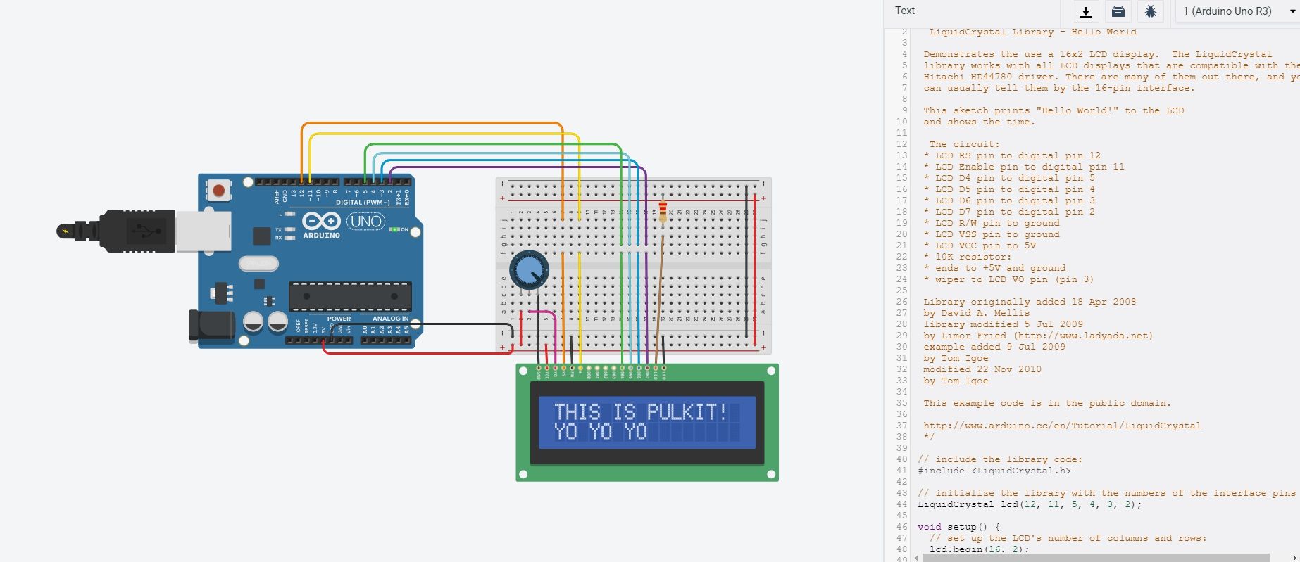
This is for a single LCD screen
                                          LiquidCrystal Library - Hello World

                                          Demonstrates the use a 16x2 LCD display.  The LiquidCrystal
                                          library works with all LCD displays that are compatible with the
                                          Hitachi HD44780 driver. There are many of them out there, and you
                                          can usually tell them by the 16-pin interface.

                                          This sketch prints "Hello World!" to the LCD
                                          and shows the time.

                                           The circuit:
                                          * LCD RS pin to digital pin 12
                                          * LCD Enable pin to digital pin 11
                                          * LCD D4 pin to digital pin 5
                                          * LCD D5 pin to digital pin 4
                                          * LCD D6 pin to digital pin 3
                                          * LCD D7 pin to digital pin 2
                                          * LCD R/W pin to ground
                                          * LCD VSS pin to ground
                                          * LCD VCC pin to 5V
                                          * 10K resistor:
                                          * ends to +5V and ground
                                          * wiper to LCD VO pin (pin 3)

                                          Library originally added 18 Apr 2008
                                          by David A. Mellis
                                          library modified 5 Jul 2009
                                          by Limor Fried (http://www.ladyada.net)
                                          example added 9 Jul 2009
                                          by Tom Igoe
                                          modified 22 Nov 2010
                                          by Tom Igoe

                                          This example code is in the public domain.

                                          http://www.arduino.cc/en/Tutorial/LiquidCrystal
                                          */

                                         // include the library code:
                                         #include

                                         // initialize the library with the numbers of the interface pins
                                         LiquidCrystal lcd(12, 11, 5, 4, 3, 2);

                                         void setup() {
                                           // set up the LCD's number of columns and rows:
                                           lcd.begin(16, 2);
                                           // Print a message to the LCD.
                                           lcd.print("PULKIT TALWAR");
                                         }

                                         void loop() {
                                           // set the cursor to column 0, line 1
                                           // (note: line 1 is the second row, since counting begins with 0):
                                           lcd.setCursor(0, 1);
                                           // print the number of seconds since reset:
                                           lcd.print("YO YO YO");
you can use this code by just clicking and copying it
And if you want to download the CODE which i used ,you can click on this link for that
LCD_prgramming5. Brushless D.C FAN
This output device is suppose to be fit in my final project and upto this point we got access of the lab after long period of lockdown
This video taught me lot of things like , what is pwm and how to connect the mosfet and how we can control the motor
Initially i was very confused in choosing the best fan in the start ,as i dont have any idea how much rpm or cfm i required so i bought these typpe of fan and i have attached them to Regulated D.C variable power to check the air push they are giving
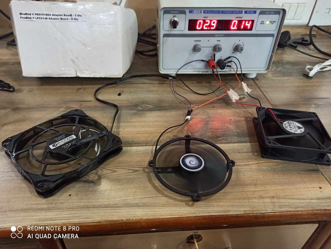
All the fans can work upto 12V power supply
Initially i saw that the fan in the right is giving maximum air but it was also giving maximum nnoise as well and the fan in the left gives less air but is the most silent one also and middle 1 was average
In this video you can see that i have stack 2 fans on each other n same configuration , as i read that if we put fans in series the air pressure will be increased and it happens , the pressure was increased
Controlling speed
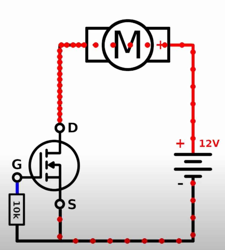
First aded an N-chanel mosfet to the circuit and use it as a gate,
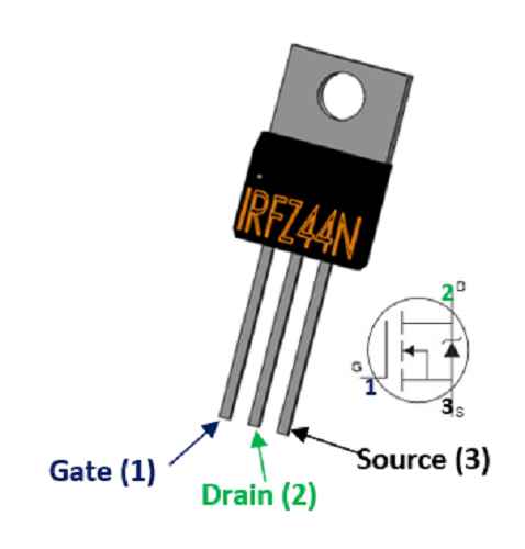
Your required this mosfet named by IRFZ44N ,it is an N- channel mosfet
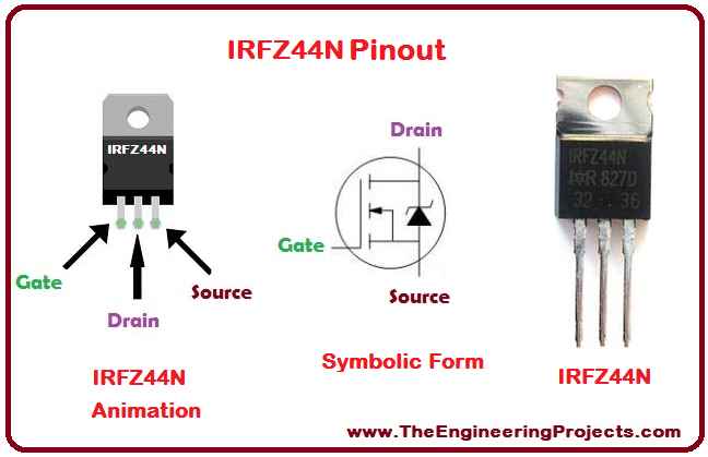
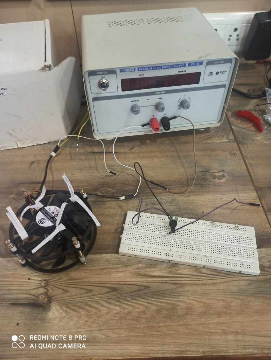
I have place the mosfet and make the neccesary connection
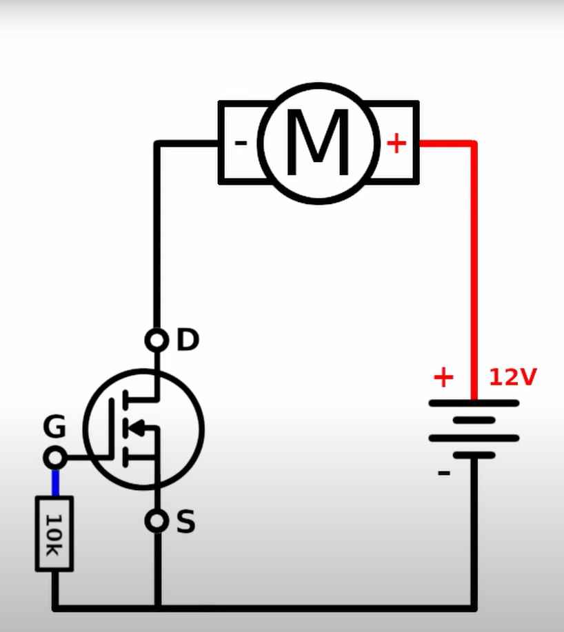
Through this image you can see how it works
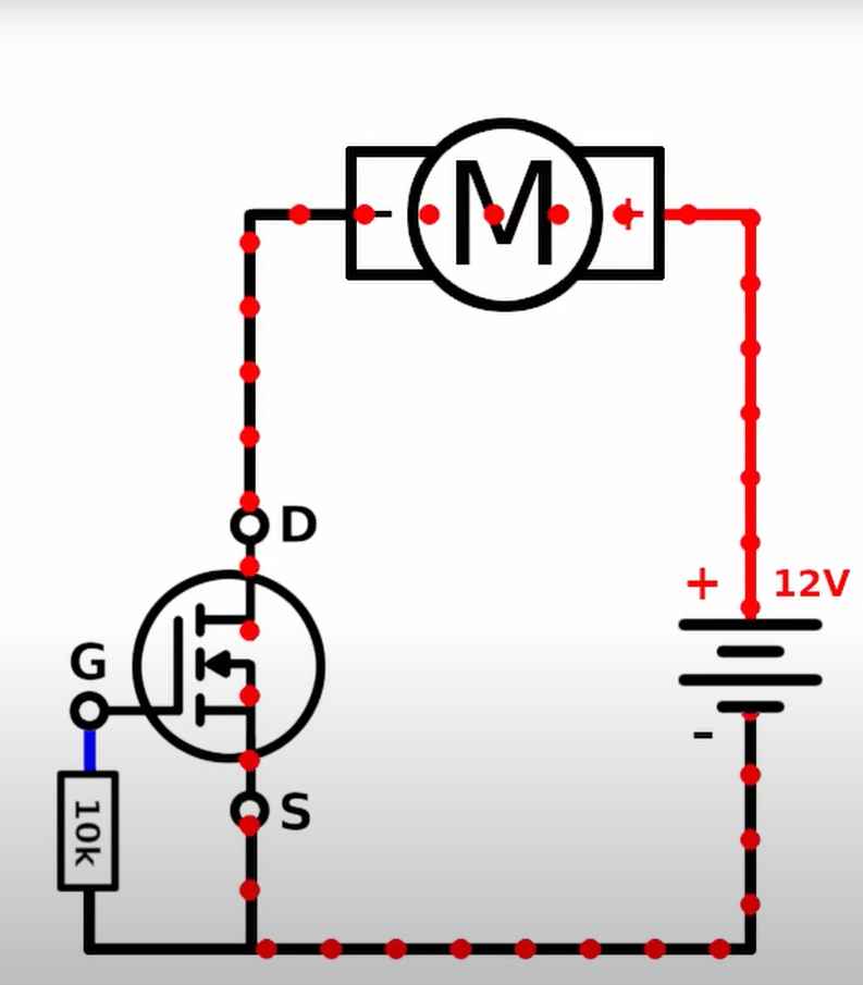
When NPN Mosfet gate is given positive power currents starts flowing and fan starts working and when -ve power is given gate gets closed
By going through this video you can understand what i am trying to do
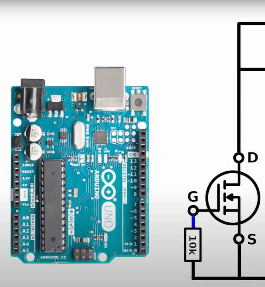
Now its time to connect to Arduino so i can program it
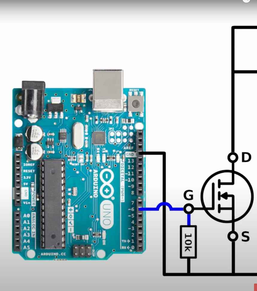
I have connected the Mosfet Gate pin to Arduino PWM 6 pin and Mosfet ground to Arduino ground
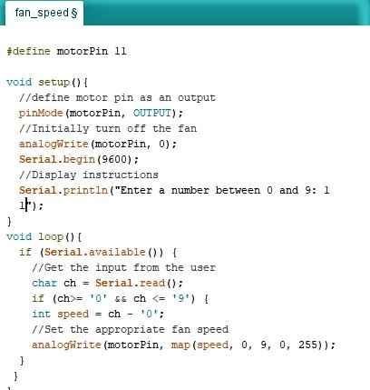
And wrote this basic code and upload it to Arduino
#define motorPin 6


void setup(){
  //define motor pin as an output
  pinMode(motorPin, OUTPUT);
  //Initially turn off the fan
  analogWrite(motorPin, 0);
  Serial.begin(9600);
  //Display instructions
  Serial.println("Enter a number between 0 and 9: ");
}
void loop(){
  if (Serial.available()) {
    //Get the input from the user
    char ch = Serial.read();
    if (ch>= '0' && ch <= '9') {
    int speed = ch - '0';
    //Set the appropriate fan speed
    analogWrite(motorPin, map(speed, 0, 9, 0, 255));
  }
 }
}
you can use this code by just clicking and copying it
And if you want to download the CODE which i used ,you can click on this link for that
Motor_controlling_program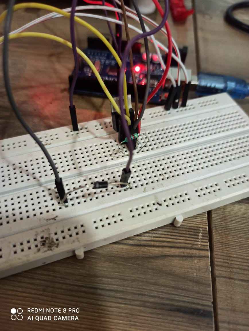
As you can see that on giving commands through serial monitor you can control the speed
PROBLEM FACED
This problem took me 3 days to solve , once i give ON command the fan starts , but when i try to give "0" value to stop the fan it didnt work , fan slows down but not stop until i remove power , because of this
Once mosfet gates open and fan starts moving it generate a small amount of current on its own which keep's the gate opened
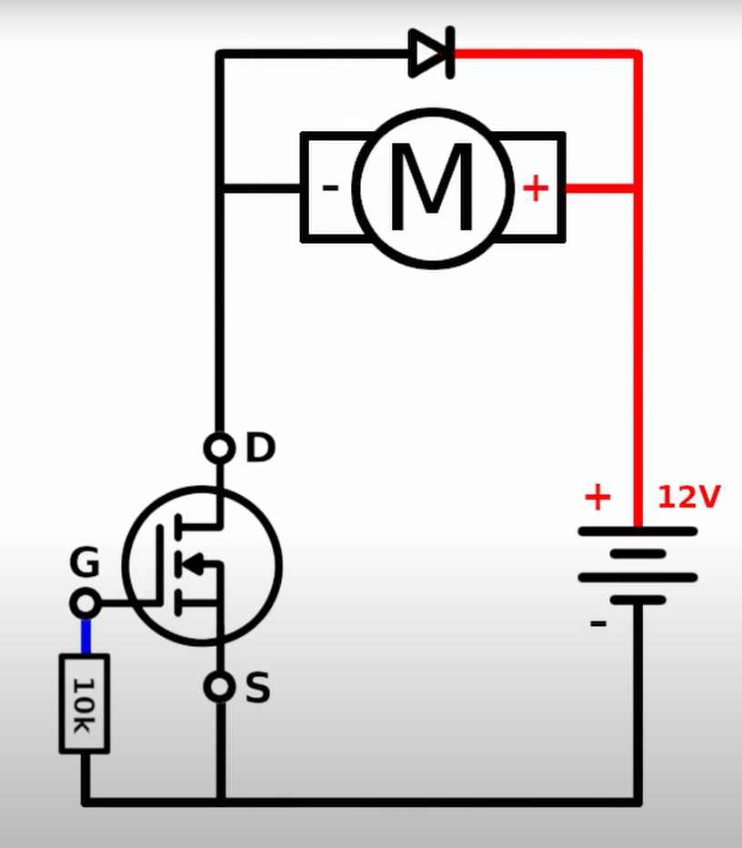
Solution for this problem was that , we require to add an diode to circuit
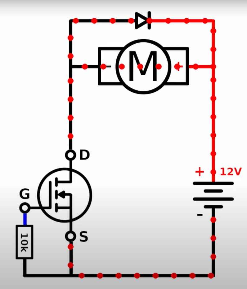
It will help to regulate the extra current , which was being produced , and from this point my fans work according to my command
Controlling Fan with my PCB
Well upto this week i was able to create my FInal board PCB and i have controlled it using that , if you would like to know about that more please click on this link and you will be guided to my final page where i have documented its making
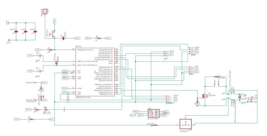
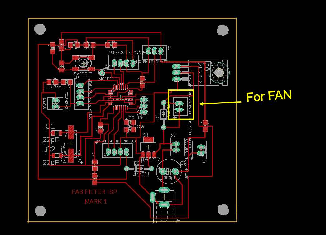
This is schematic for my final PCB
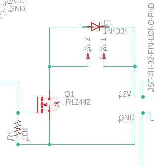
As you can see i have made same schematic in the final circuit as i have explained previously
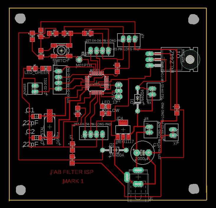
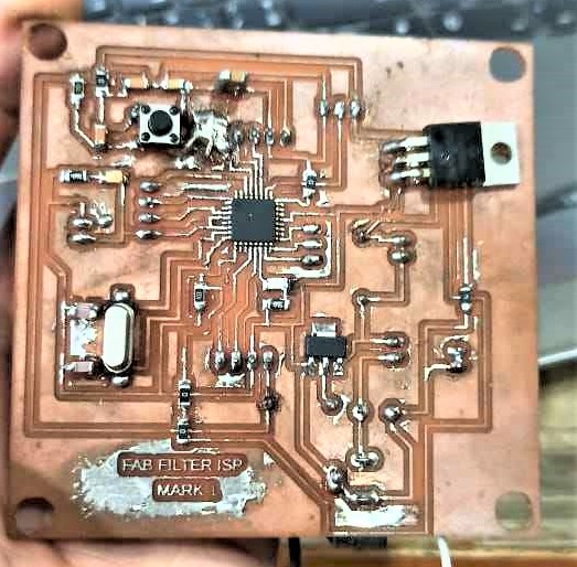
Thats how my final PCB looks
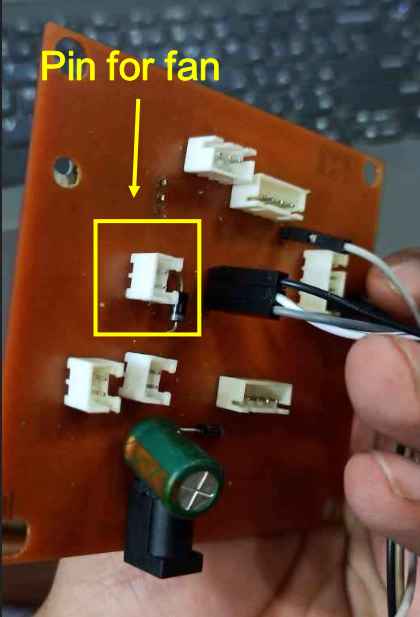
This is point for fan
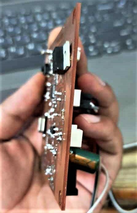
After all the components are soldered
Video of controlling speed using my pcb
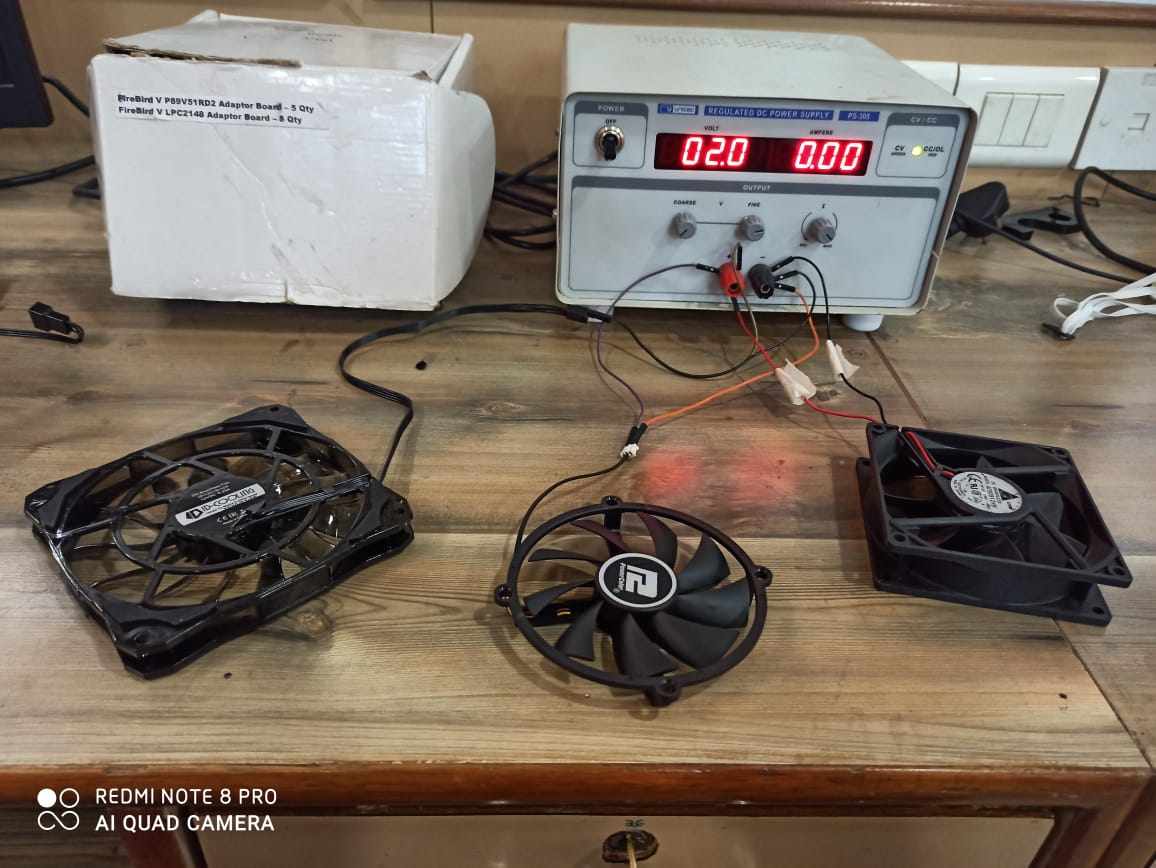
Group Assignment:
In group assignment we have to measure power of output device.So we decided to measure power consumption of DC Geared motor. We Connected the Motor to a Variable power supply and observed the current drawn by the motorOBSERBATIONS
We noticed that when we provide 4V of voltage consumption of current is around 60ma and as we increase the voltage the current consumption is also increase
                                          Using formula P=VI
Here P = Power
>V = voltage
I = Current
P = 0.06 * 4 = 0.24 Watt
P = 0.11 * 10.5 =1.15 Watt
So the power consumed by motor at No load ranges from 0.24 Watts - 1.1 Watts
you can use this code by just clicking and copying it