Interface & Application (WEEK 13)
Individual Assignment:
- Write an application that interfaces a user with an input &/or output device that you made
Group Assignment:
- Compare as many tool options as possible
IMPORTANT NOTE : ALL OF MY IMAGES ARE POP UP IMAGES , IF YOU HAVE ANY PROBLEM READINGS THOSE IMAGES , PLEASE CLICK ON THEM AND THEY WILL ENLARGE AUTOMATICALLY AND YOU CAN READ THEM EASILY
Individual Assignment:
1. MIT APP INVENTOR

MIT App Inventor is a web application integrated development environment originally provided by Google, and now maintained by the Massachusetts Institute of Technology (MIT). It allows newcomers to computer programming
to create application software(apps) for two operating systems (OS): Android, and iOS, which, as of 8 July 2019, is in final beta testing. It is free and open-source software released under dual licensing: a
Creative Commons Attribution ShareAlike 3.0 Unported license, and an Apache License 2.0 for the source code.
It uses a graphical user interface (GUI) very similar to the programming languages Scratch (programming language) and the StarLogo, which allows users to drag and drop visual objects to create an application
that can run on android devices, while a App-Inventor Companion (The program that allows the app to run and debug on) that works on iOS running devices are still under development. In creating App Inventor,
Google drew upon significant prior research in educational computing, and work done within Google on online development environments.[1]
If you want to try it out you go to there official website by clicking on this link
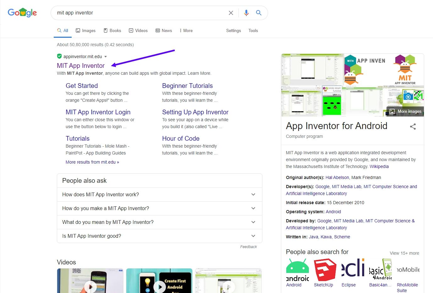
either you can search on google "MIT APP INVENTOR" or by clicking on the link i have mentioned above you can access the site

This is there official site

First click on the create app
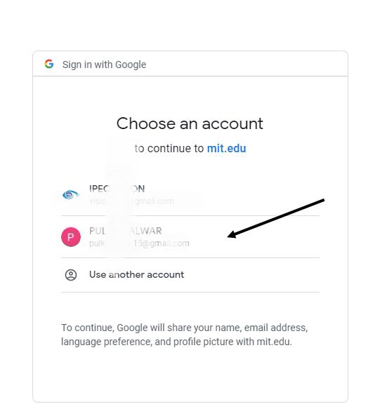
Then sign in using your Gmail account
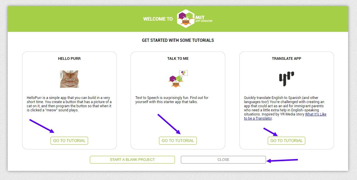
I will recomend you go through the tutorial's provided when you first sign in
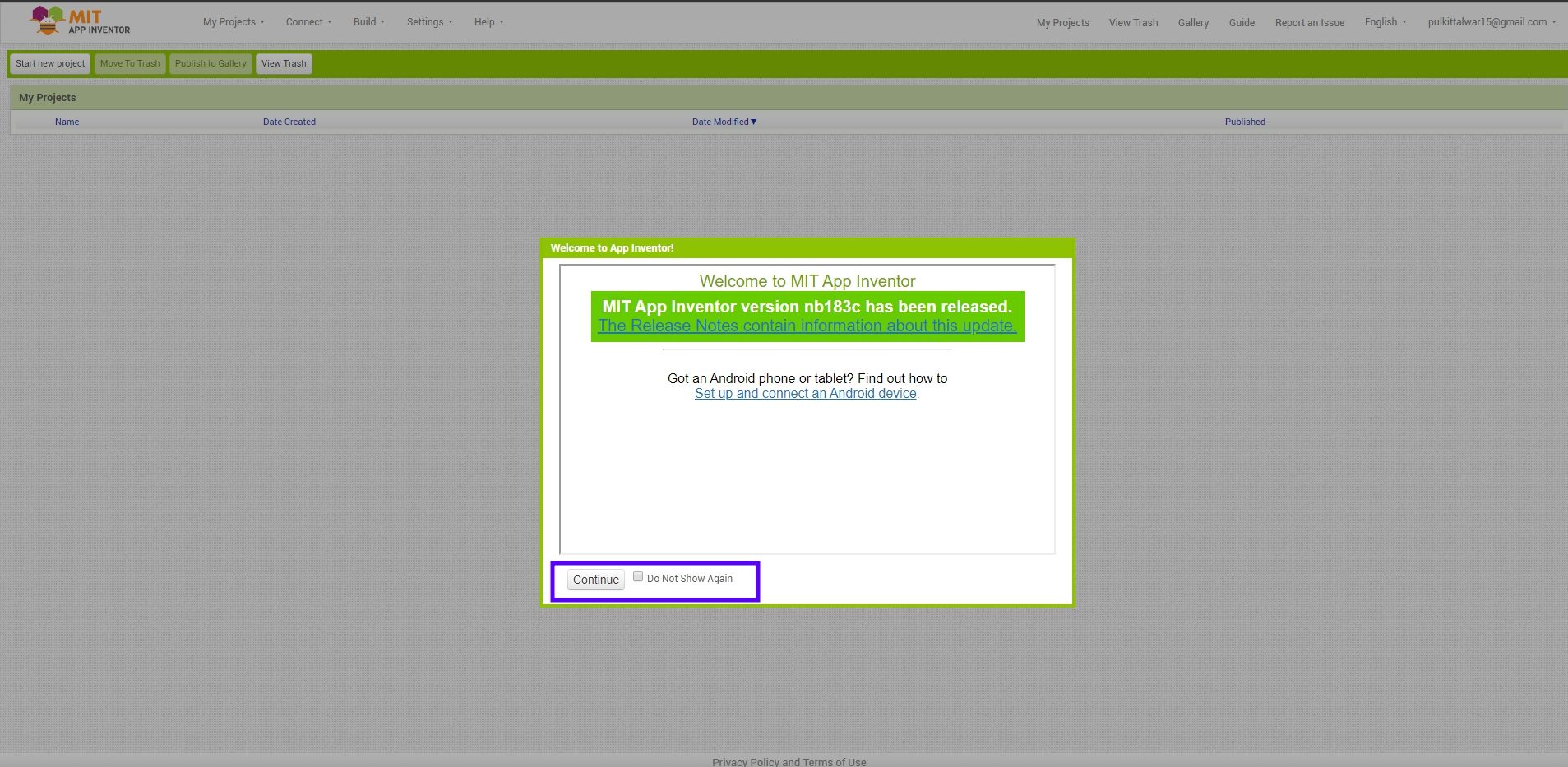
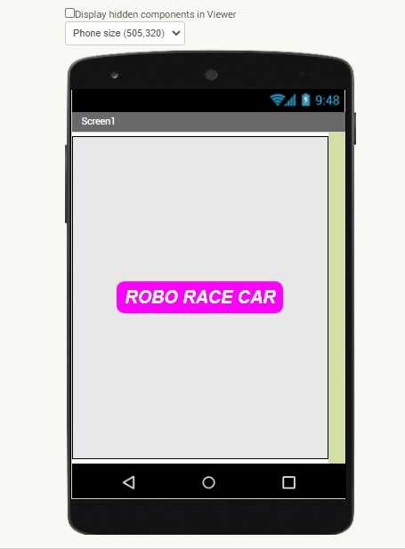
Image displaying app
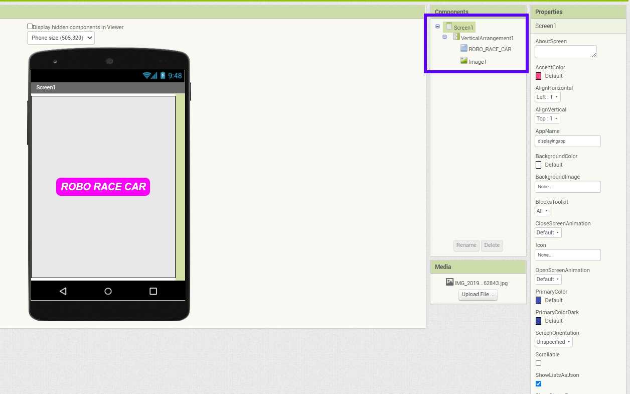
This is the first app which i made , it is a basic one which only display image
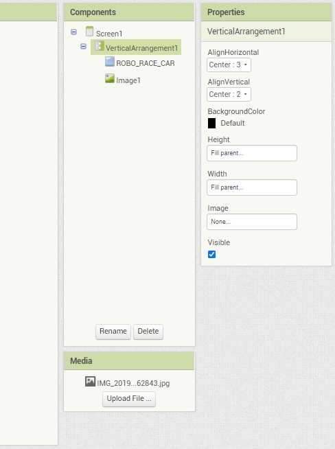
These are basic components i used
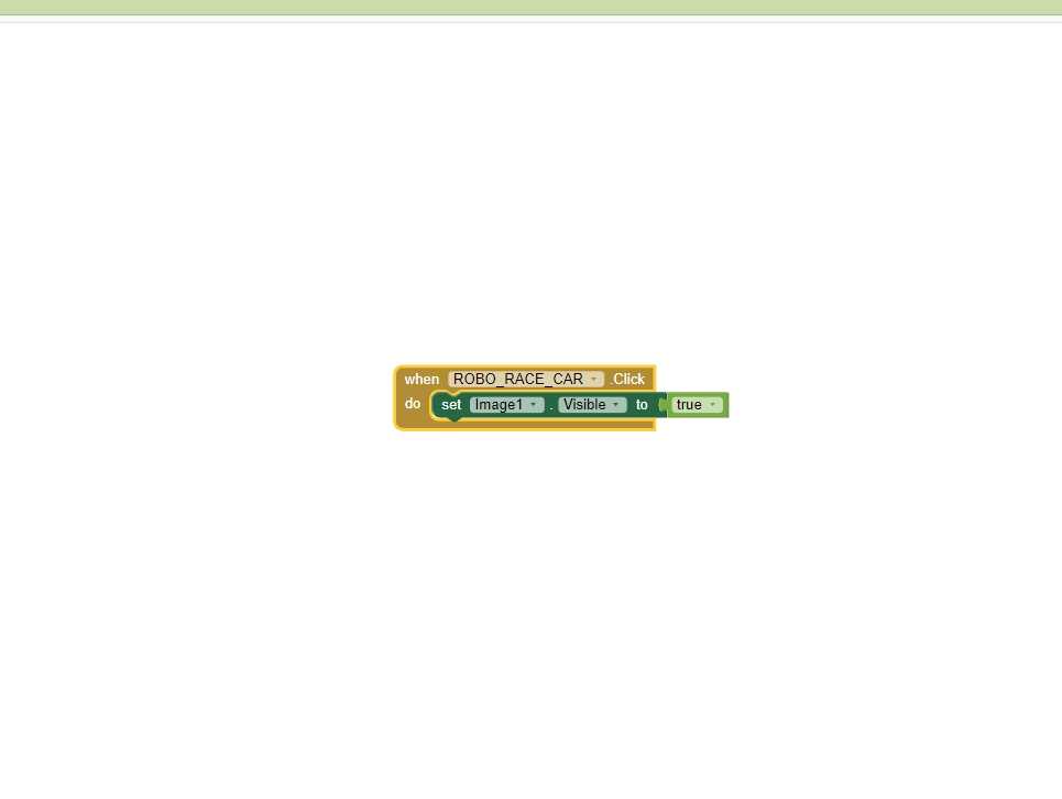
Block for the app
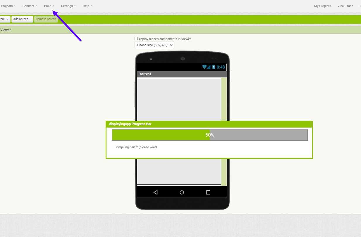
Once the app is made i click on build >> APP (provide QR code for .apk)
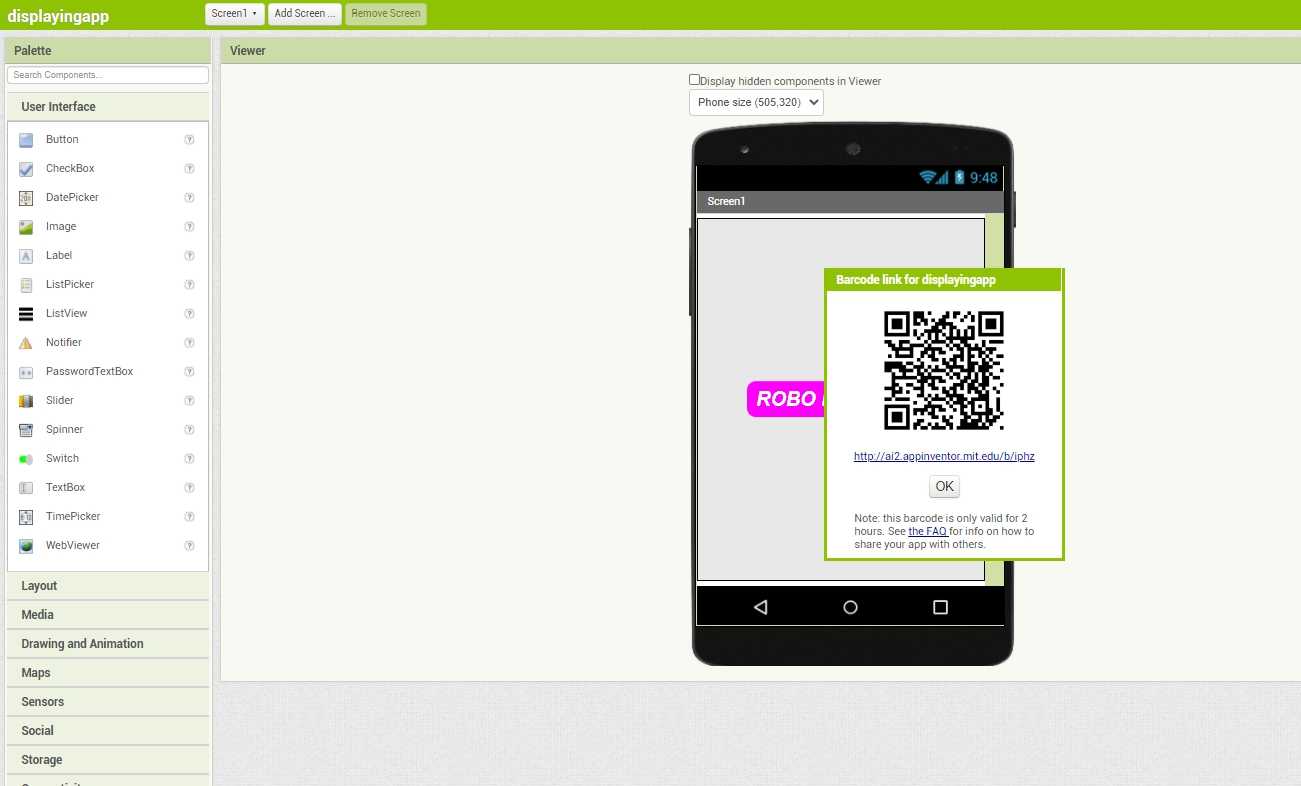
And after seberal minute of wait i got this Qr code which i scanned using , my mobile MIT app inventor app and i got hte downloaded
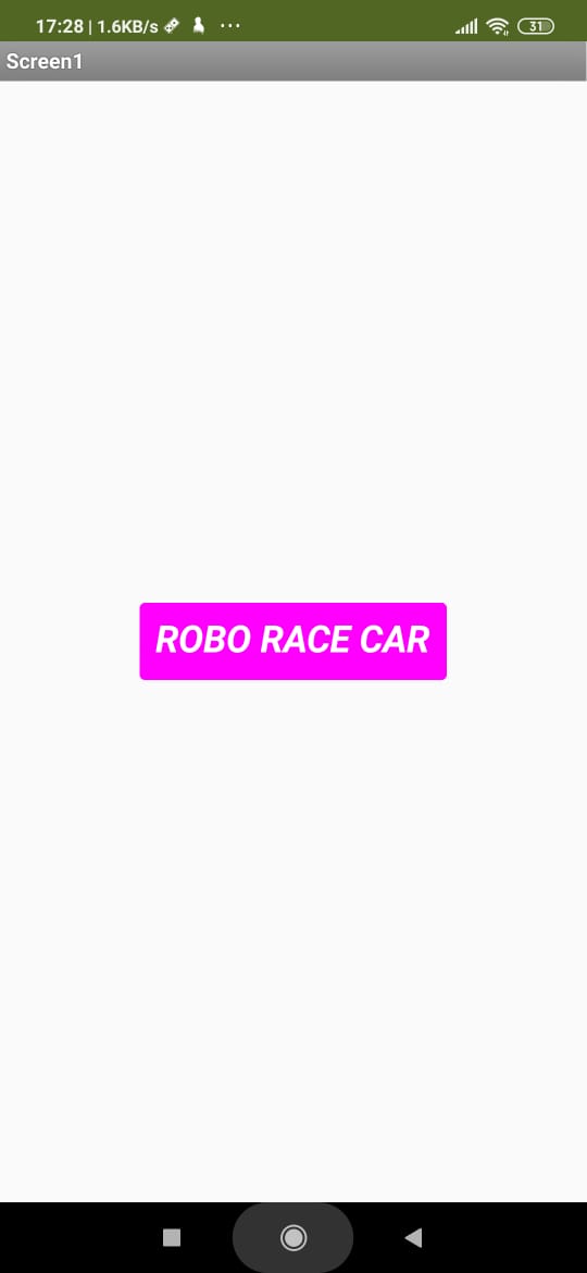
Open the app in our mobile and something like this will appear
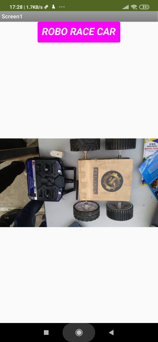
When i click on "ROBO CAR "this image will appear , as hwat i have made
In thid video have explained how to make a basic photo displaying app
Controlling led using MIT APP
Creating app first
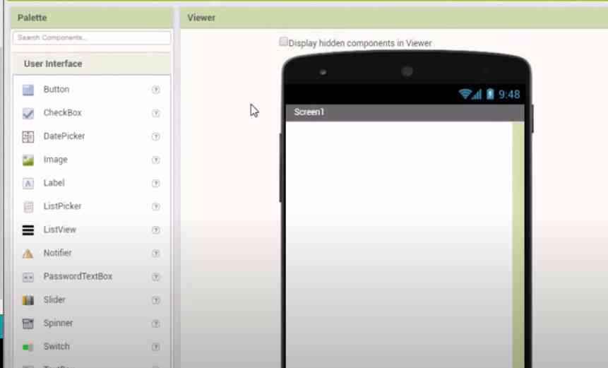
I named this app bluetooth
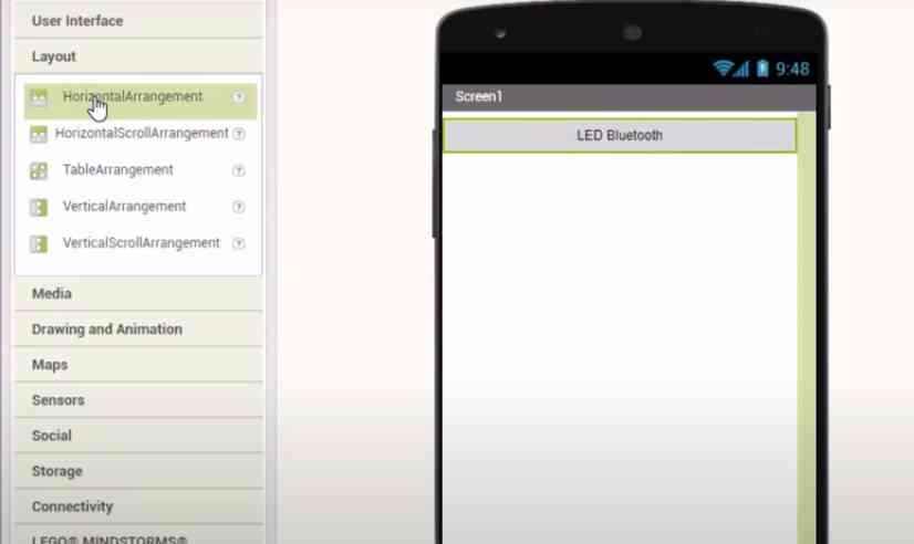
First giving Horrizontal arrangement from layout
Naming it "LED Bluetooth"
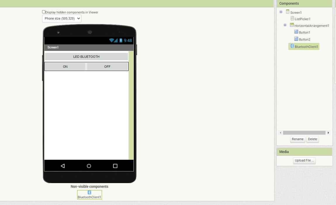
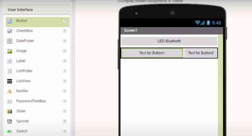
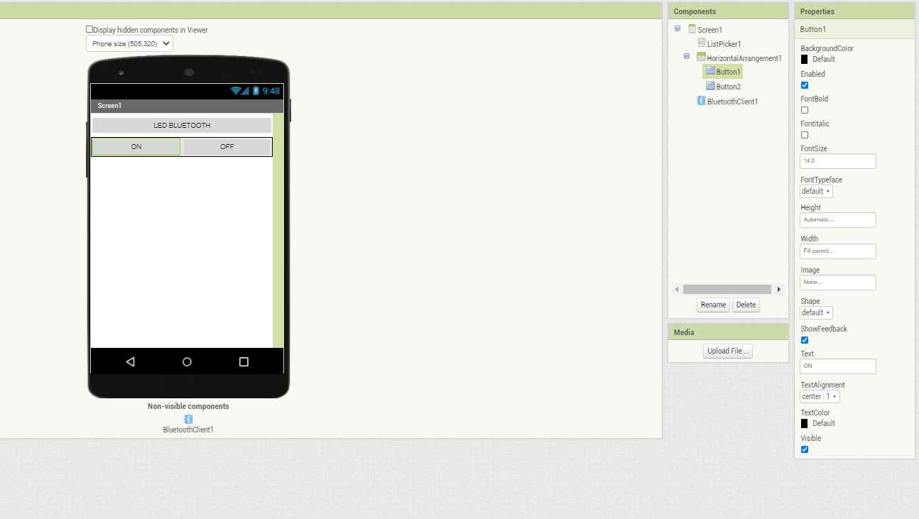
Then giving 2 more Horizontal arrangement and giving them eqaul space
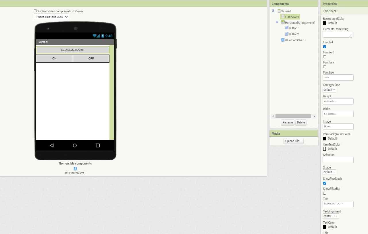
Namin them ON and OFF respectively
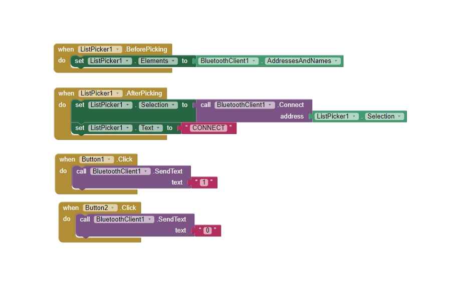
This will be the block for the app
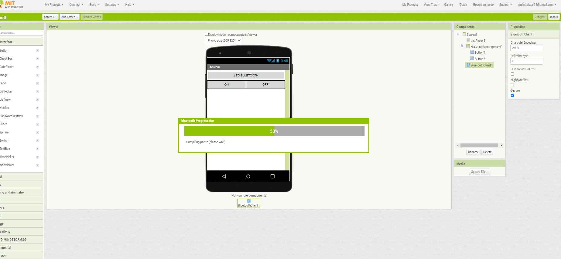
After everything is completed just click build in the same manner as the previous app
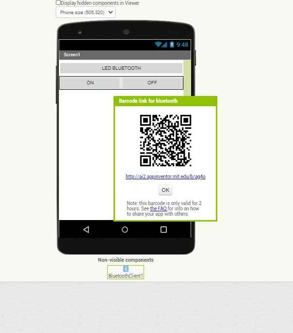
And scan the code to download your app in your phone
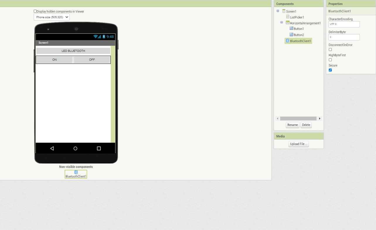
Wiring for the control
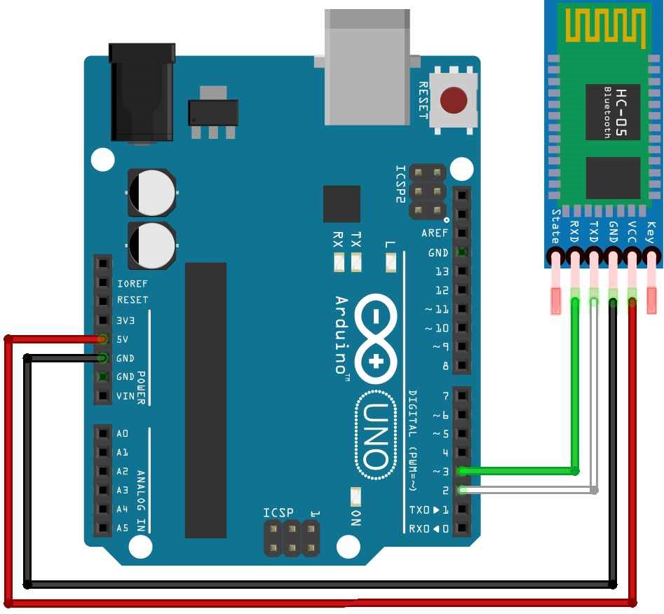
Code for Connecting bluetooth to Ardiono ass well as My pcb
                                            #include SoftwareSerial mySerial(0, 1); // RX, TX
                                            char Incoming_value = 0;

                                            void setup()
                                            {
                                              mySerial.begin(9600);
                                              pinMode(10, OUTPUT);
                                            }

                                            void loop()
                                            {
                                              if(mySerial.available() > 0)
                                              {
                                                Incoming_value = mySerial.read();
                                                //mySerial.print(Incoming_value);
                                               // mySerial.print("\n");
                                                if(Incoming_value == '1')
                                                  digitalWrite(10, HIGH);
                                                else if(Incoming_value == '0')
                                                  digitalWrite(10, LOW);
                                              }
                                            }
And if you want to download the CODE which i used ,you can click on this link for that
Bluetooth_interfacing_codeI first tested my code as well as app with arduino , so this video shows you its working
Similarly this video shows the working in my PCB
Proccesing
Processing is an open-source graphical library and integrated development environment built for the electronic arts, new media art, and visual design communities with the purpose of teaching non-programmers the fundamentals of computer programming in a visual context.
If you want to try it out you go to there official website by clicking on this link
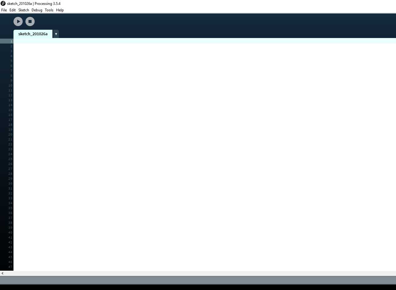
First install the software by clicking on the link i have given above
Then please write the code i have written ( code is Given below)
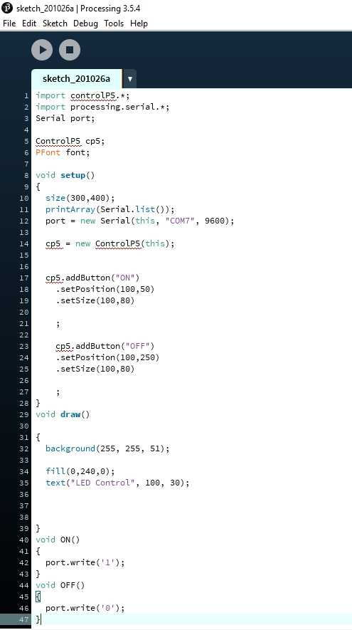
CODE For PROCESSING
                                            import controlP5.*;
                                            import processing.serial.*;
                                            Serial port;

                                            ControlP5 cp5;
                                            PFont font;

                                            void setup()
                                            {
                                              size(300,400);
                                              printArray(Serial.list());
                                              port = new Serial(this, "COM9", 9600);

                                              cp5 = new ControlP5(this);


                                              cp5.addButton("ON")
                                                .setPosition(100,50)
                                                .setSize(100,80)

                                                ;

                                                cp5.addButton("OFF")
                                                .setPosition(100,250)
                                                .setSize(100,80)

                                                ;
                                            }
                                            void draw()

                                            {
                                              background(50, 50, 250);

                                              fill(0,240,0);
                                              text("LED Control", 100, 30);


                                            }
                                            void ON()
                                            {
                                              port.write('1');
                                            }
                                            void OFF()
                                            {
                                              port.write('0');
                                            }
And if you want to download the CODE which i used ,you can click on this link for that
Proceesing code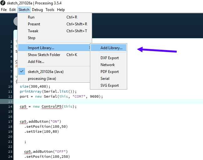
When you try to run the code the system will show that library is missing so you need to add a library , for that purpose click on SKETCH >> IMPORT LIBRARY >> ADD LIBRARY
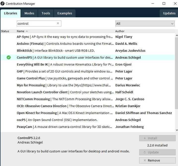
Then contribution mannager will be open , then enter controlp5 in search bar
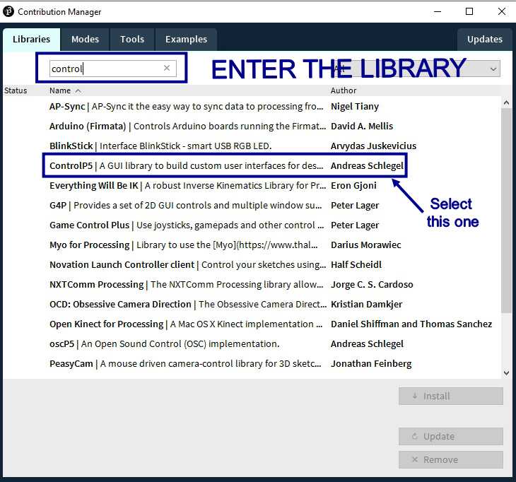
Select the respective llibrary and add it
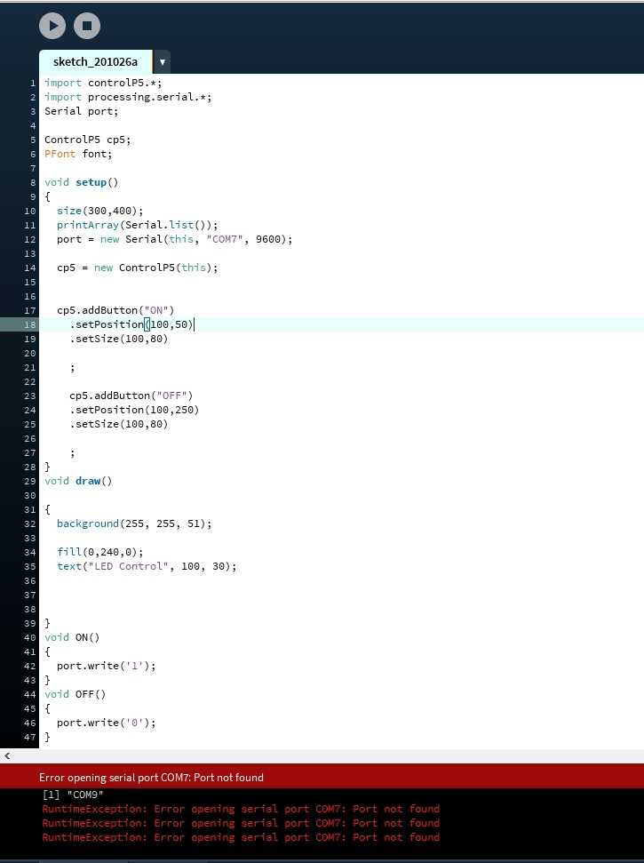
Then this time run it again , now there will be a problem shown like in processing you required to add on which COM your arduino is attached , so go on device manager and check to which COM port your device is attached and enter the port name to program and try to run it again
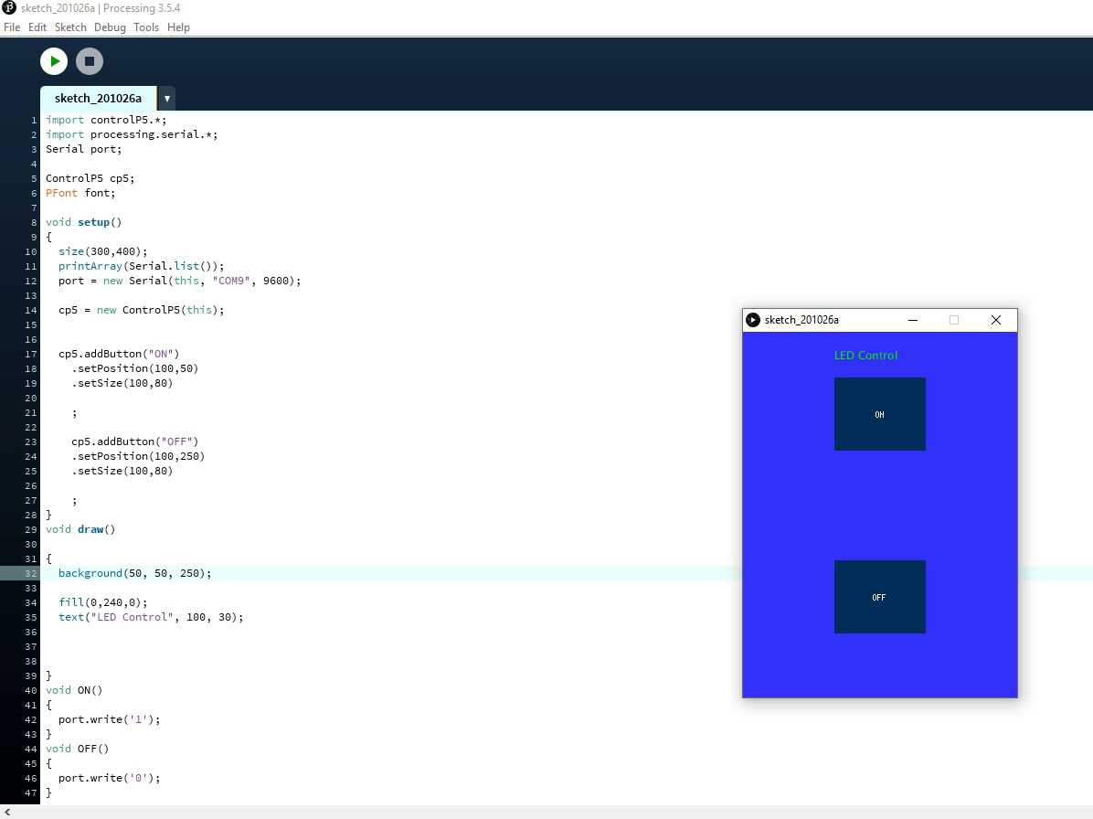
If everything goes perfectly you will get a small menu like this apppeared on your screen
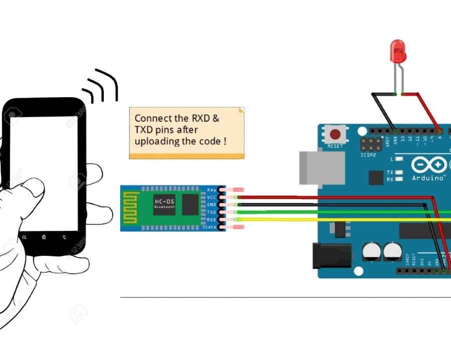
Then connect your PCB with arduino like what i have done in Week 9 , you can go and check it out by clicking n this link
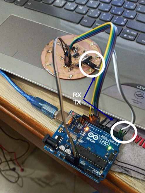
thats howconnections to be made , plus you require to connect RX- TX of Arduino to TX-rx of your PCB , so commands can gofrom one controller to another , but pls check my week9 it has more detail explanation
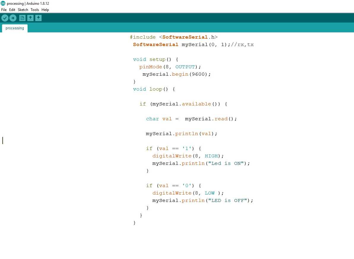
CODE FOR ARDUINO
                                            #include
                                            SoftwareSerial mySerial(0, 1);//rx,tx

                                            void setup() {
                                              pinMode(8, OUTPUT);
                                               mySerial.begin(9600);
                                            }
                                            void loop() {

                                              if (mySerial.available()) {

                                                char val =  mySerial.read();

                                                mySerial.println(val);

                                                if (val == '1') {
                                                  digitalWrite(8, HIGH);
                                                  mySerial.println("Led is ON");
                                                }

                                                if (val == '0') {
                                                  digitalWrite(8, LOW );
                                                  mySerial.println("LED is OFF");
                                                }
                                              }
                                            }
And if you want to download the CODE which i used ,you can click on this link for that
Proceesing code for arduino