Final Project
For my final project I would like to make a interactive tree that re-creates the feeling of lying under a tree looking trough the foliage at the sky and stars while you’re in your own city home. This page describes the components, how to make each part, what I would like to change and the bill of material. The full development of the final project and the weekly process can be found in the documentation of week 20: project development
Final project video and slide
After the final presentation I made a new video and added the capacitive touch to my final presentation video, as it was not clear enough during the presentation.
Final project video version 2
 Final project
Machines and tools
- Laser cutter
- Vacuum former
- UV printer
- Shopbot
- Vinyl cutter
- PLPKF Protomat
- Ultimaker 2
- Sewing machine
- Dremmel
- Soldering Iron
Software
- KiCad
- Circuit Cam
- Fushion 360
- ExactFlat
- Slicer for Fushion 360
- Adobe Illustrator
- Adobe Premiere
- Adobe Photoshop
- Cura
- Sublime text
- Arduino IDE
Bill of Material
Overview of all the materials used and their costs plus supplier. The original excel can be found here
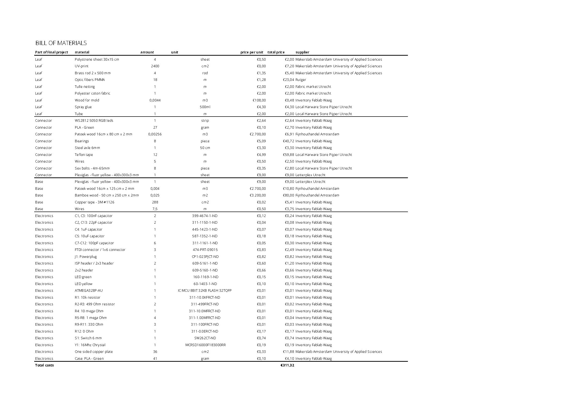 Bill of material final project
All the parts of my final project
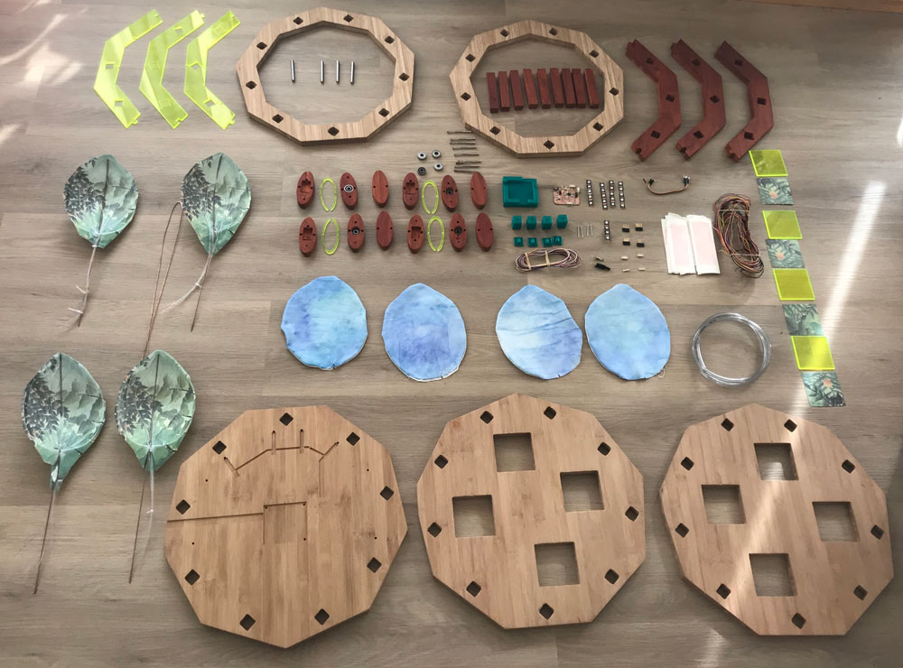 Overview of the parts of my final project
Files
- Bill of Material
- STL-file 3D print Neopixel connector base
- STL-file 3D print Neopixel connector top
- STL-file 3D print case Satsha kit
- Fushion 360 Neopixel case
- Fushion 360 Electronics case
- Fushion 360 Base
- Fushion 360 Leaf Connector
- Fushion 360 Mold Leaf
- Illustrator file base - CNC
- Illustrator file plexiglas - lasercutter
- Illustrator file connector -CNC
- Illustrator file capacitive touch
- Illustrator file leaf cover
- Illustrator file sliced mold leaf
- KiCad files Tree Satsha Kit
- Arduino file - Tree capactive touch with neopixel program
How to make the Leaves
During the Fab Academy did a lot of prototyping to get the right sort of leaf. In the end I came up with the following development process.
Step 1: Design a 3D mold
My first step was to design a 3d mold for my leaf so I could use it in the vacuum former.
- Start with 2D sketch of a leaf in Fushion 360
- Extrude the sketch
- Go to the skulpt mode.
- On top of the sketch skulpt a plane in such a way that it give a nice curve.
- Slice the body of the extrude leaf with the plane from the skult mode.
- Keep the part that you need for the mold.
- Save this body as STL-file to use in Fushion slicer
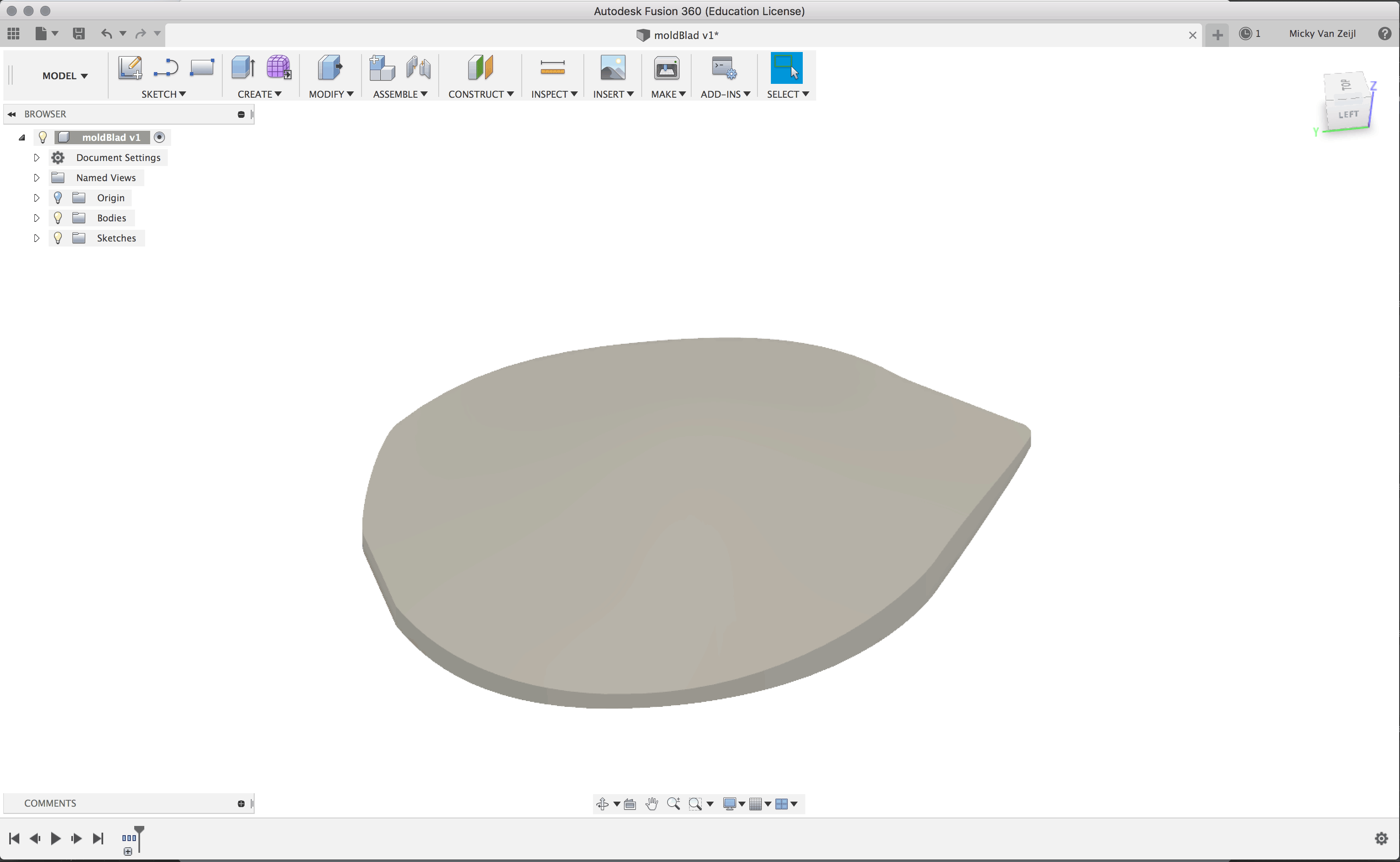 3D design mold for leaves
Step 2: Make the mold
After the 3D design I could create the mold. You can use the STL file and CNC foam. However I sliced it and laser cut the mold, due to opening times of the lab.
- Import the STL file in Slicer for Fushion 360
- Make vertical slices, this gives a more detailed finish
- Download the plans from Slicer
- Open these in Illustrator and save as Illustrator CS2 for the laser in the Fab Lab of the Waag.
- Get the material you need and place it in the laser.
- Follow the steps as described in week 3, while using the laser cutter.
- When finished, glue each part on top of each other, make sure to have a guide.
- Sand the mold so it’s smooth.
- Now you’re ready to use the mold.
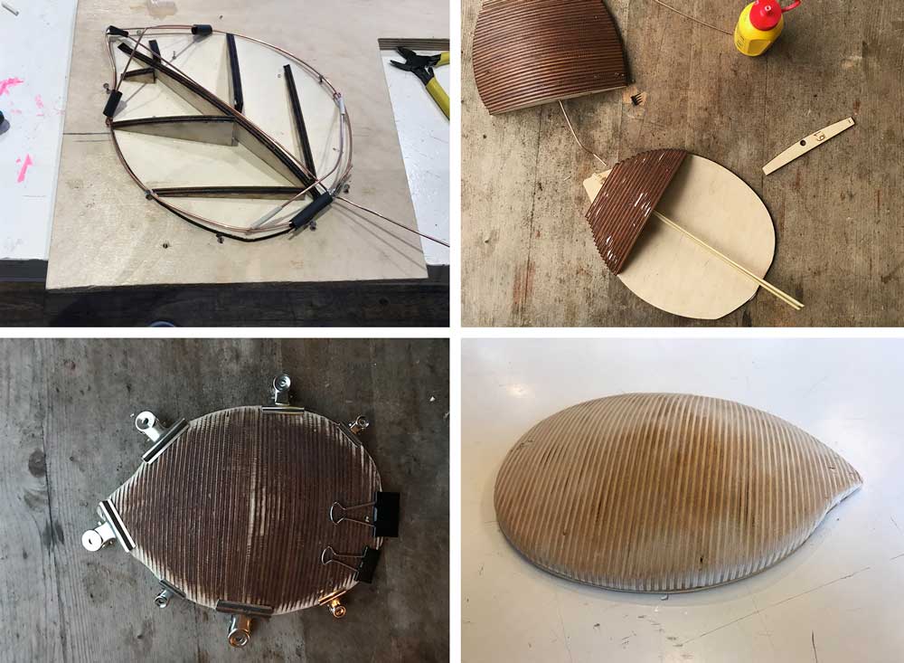 Making the mold for the leaf
Step 3: Make the leaves from fabric.
Next step was to make the leaves. I use polyester for the outside and tulle for the inside.
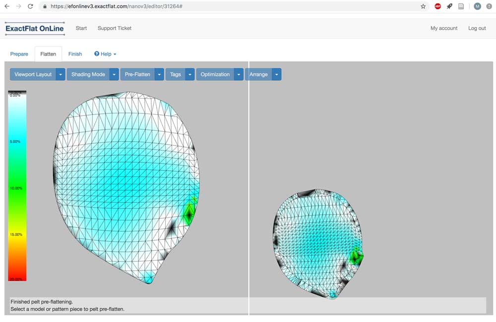 Exact Flat 2D pattern design
- In Fushion 360, use the plug-in Exact Flat. Select the faces for a 2D pattern design.
- Export it to exact flat and go to the online editor.
- In exact flat use the pre-flatten tool to flatten the 3D shape to a 2D pattern, more detail on this process can be found in my documentation of week 10.
- Export and download the pdf file of the 2D-pattern
- Open pdf in Illustrator. I use the inside line for the tulle and the line with zoom for the polyester fabric.
- Place the fabrics in the laser and laser cut the parts.
- For the polyester parts, I used watercolor paint for the outside. Normally fabric dye would give a better result but for time reasons I took watercolor paint. It gives a nice effect.
- I used the tulle in the vacuum forming process as place holder for the optic fibers.
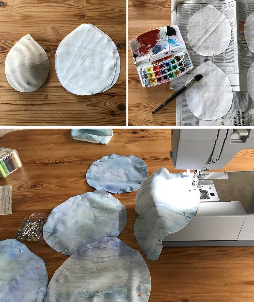 Fabric cover for leaves
Step 4: Making the leaf pattern
To create the feeling of foliage, I used the UV-printer.
- Select the image you want, normally I would produce my own image but this time I used parts of a painting by Rousseau.
- Select the part you want to print.
- Place the material in the UV-printer. I printed the images on polystyrene that I will use for the vacuum former later on.
- Make sure the setting are okay, more details on this part can be found in the documentation of week 20.
- Press print and print all four pieces.
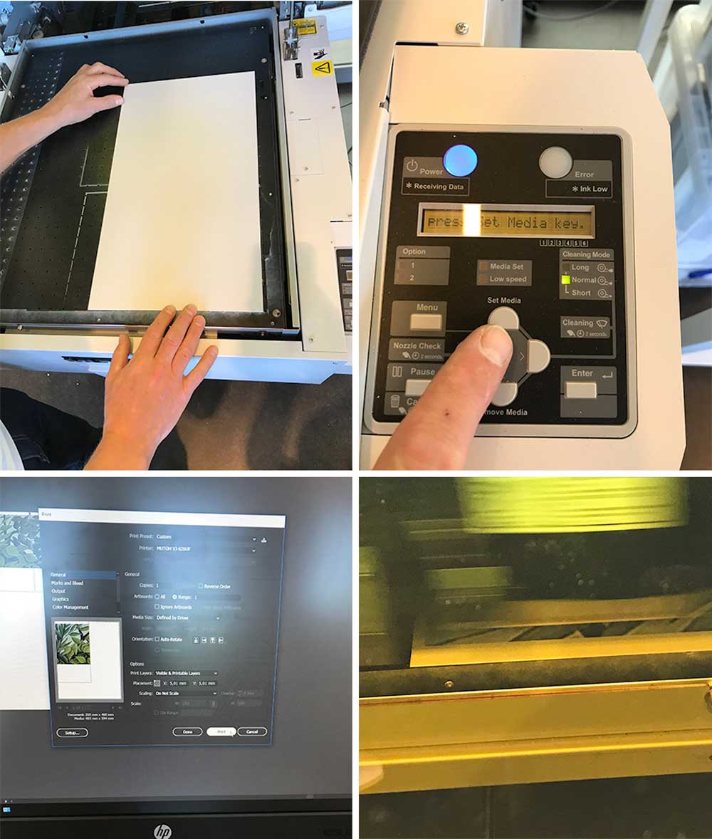 UV-printing of polystyrene for leaf
Step 5: Producing the leaves.
Now we have all the parts together and it’s time to assemble the basics.
- Use brass or copper wire for the petiole. I place it over my mold.
- Weave the wire together with the optic fiber through the tulle place this on top of the mold.
- Place this all together in the vacuum former.
- Place the UV-printed polystyrene sheets with the printed image down in the machine.
- Vacuum form the polystyrene over the mold with the tulle, optical fibers, and brass rod.
- I used spray glue after this process to make sure the optical fibers keep stuck to the cover.
- sew the two polyester fabrics together, make sure to leave a hole.
- place the leaf inside the cover made from polyester fabric.
- Close the fabric cover, this is optional. In the end I didn’t add the fabric covers because it was a bit more difficult to see the light and the print.
- Add extra brass rod or copper rod at the end so the twig has more stability with the connector.
- Add the tube around the optic fiber and brass rod.
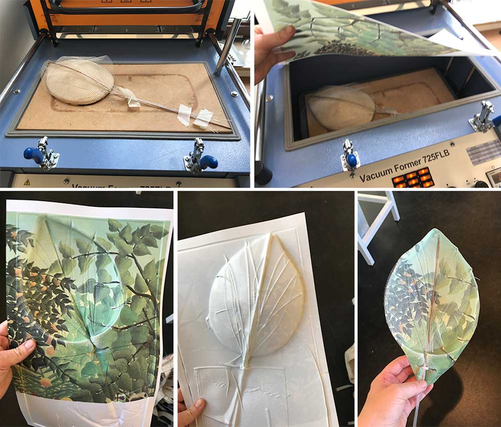 Making the leaves
How to make the connectors
It took me a while to figure out how I would design the connectors between the leaves and the base, because I had several parts to keep in mind:
- There should be a solid connection between Neopixel and Optical Fibers
- There should be room for wiring
- It should hold the leaf construction
- It should be able the create movement.
Step 1: Neopixel optical fiber connector
First I designed a connector for the optic fibers as it’s very subtle how these are connected to get the right effects.
![]() Bottom of Neopixel connector
Bottom of Neopixel connector
- Make sure to get the right measurements for the Neopixel.
- Open Fushion 360, start with a sketch.
- Extrude the parts you need. As shown in image above and the Fushion 360 file of my design on top of this page.
- I created six holes for wiring.
- I made sure the Neopixel would really pop-up with an extrude placement.
- The top part clicks in nicely onto the bottom part.
- The Neopixel now, fits into the the beam hole of the top part.
- Solder the wires to the neopixel.
- Weave the wires through the holes on the bottom.
- Place the Neopixel with the wire on top. Make sure the sides bent a bit.
- Put the beam hole on top.
- Connect this part with the optical fibers of the leaf.
![]() Top of Neopixel connector
Top of Neopixel connector
Step 2: Design of the connector hub
To make sure the Neopixel connector above stays put and the leaf stays hanging I created a connector hub. That connects these parts to the base. I wanted them to move and keep moving like a pendulum. I did a lot of tests with springs. In the end I decided that I will leave this part for future development. As it takes a lot more testing to fine tune. For now the movement is created with the bearings in steel rod.
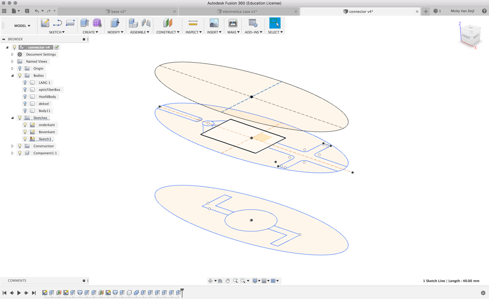 Design Connector Hub
- Take the measurements of the neopixel connector or include the design in your new Fushion 360 design.
- place them within a eclipse. My version is 40 mm x 100 mm.
- Make sure to add a hole at the back for wiring and placement of the optic fibers and brass rod.
- The lowest part needs a pockets for the bearings.
- Add holes to connect all three parts with sex bolts.
- Export parts from Fushion 360 as DXF.
- Use the DXF files with the Shopbot
- I used the red Patoek wood for the connectors.
- I made some thinking mistake in my design. I turned the position of the wiring around, so in the end I had to drill holes at the other side of the connector
- Another mistake I made was the mill I used. Because I didn’t have much time I thought I would save time with a 6mm mill, I forgot that my design was based on a 4mm mill. So some pockets ended up missing of not working the way I wanted.
Combining the leaf with the connector
I connected all four leaves to the connector with the Neopixel connection block inside it. These parts can be assembled with the Base.
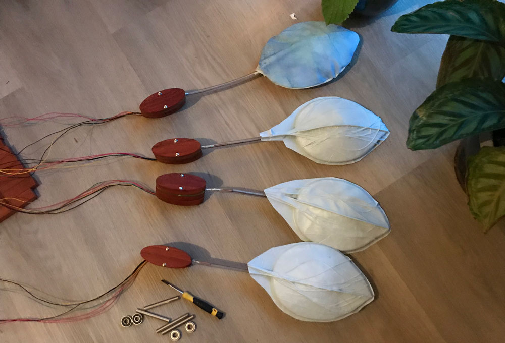 Connector with leaves
How to make the base
For the base I used bamboe and patoek wood combined with neon plexiglas. I sliced the 3D design in layers of these materials and placed them on top of each other. Where they will be held with the wooden side parts. I designed it in Fushion 360.
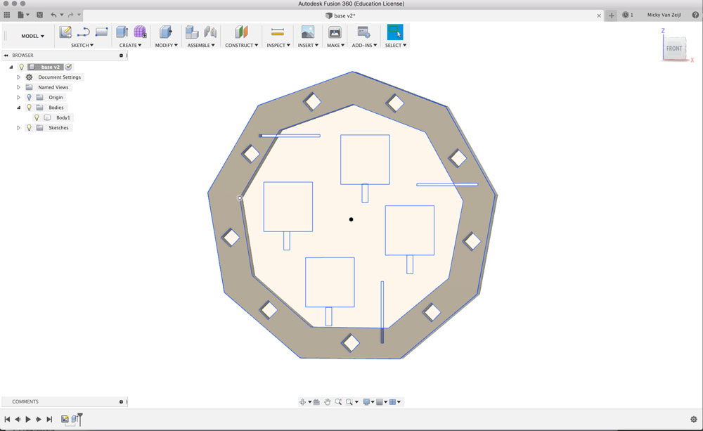 Base design
Import requirements for the base were:
- It should have enough space for the connectors.
- It should have holes, placement for wiring.
- It should be solid
- No glue should be required
Combining the leaf with the connector
How to make the electronics
More details on the electronic design can be found in my documentation of week 20. I made Satsha kit with two extra elements included in the design and I left a lot of pins open for future projects. Or for debugging when needed.
- Capacitive touch - I used five pins to have five touchboard for the capacitive touch
- Neopixel connector - I used three pins to create a connector to attach three Neopixel strings.
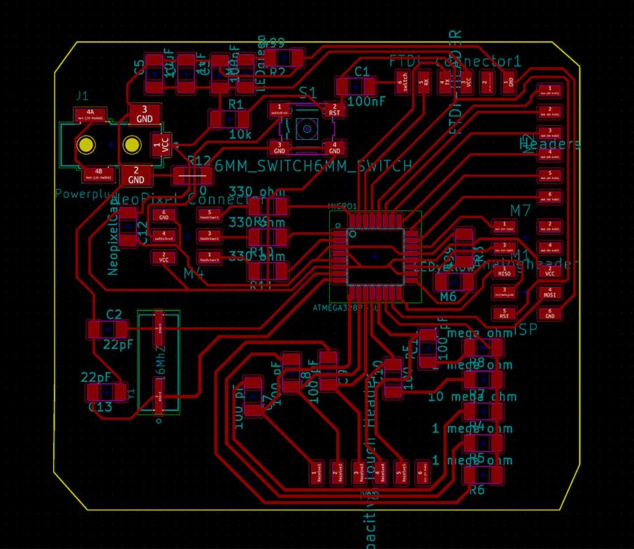 Final design of my Tree Satsha Neopixel touch board
In the design of the base, I also made sure there was enough space for wiring.
Wiring and tree-satsha board
Capacitive touch
I created to option to add 5 capacitive touch pads in the design of my board. In the end I used four pads in the design of my base and in the programming code, in the end I used four.
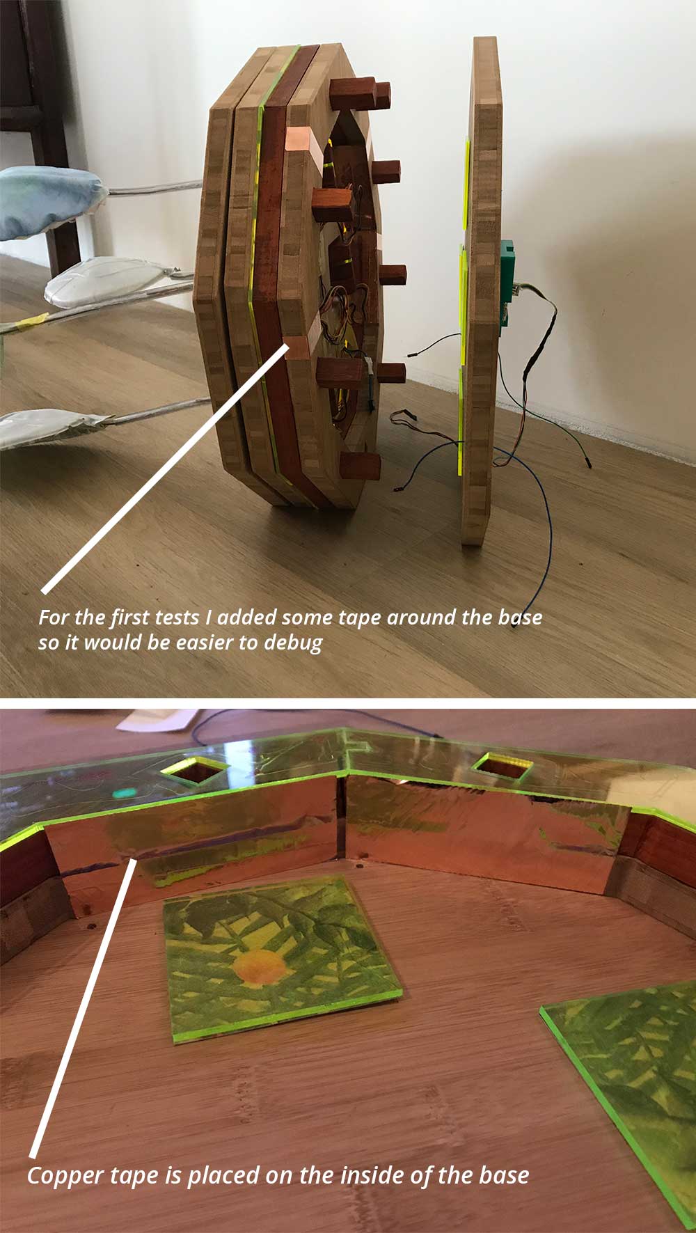 Capacitive touch
The capacitive touchpads are placed inside the frame. So you will have to touch the wood on the side to put the Neopixel on and off or to change color theme. For this moment I put some tape around the base so it would be a bit easier to debug. In the final result this part will be removed. I used the vinyl cutter to cut the tape.
Capacitive touch with copper tape
Before I added this to my final project I tested it, as I write more in detail in week 20, together with the Neopixels to make sure it works.
capacitive touch test with Neopixels
Making a case for the electronics
To make sure the Tree-Satsha board stays solid and safe, I created a case around it to attach to the back of the base in Fushion 360 and 3D-printed it.
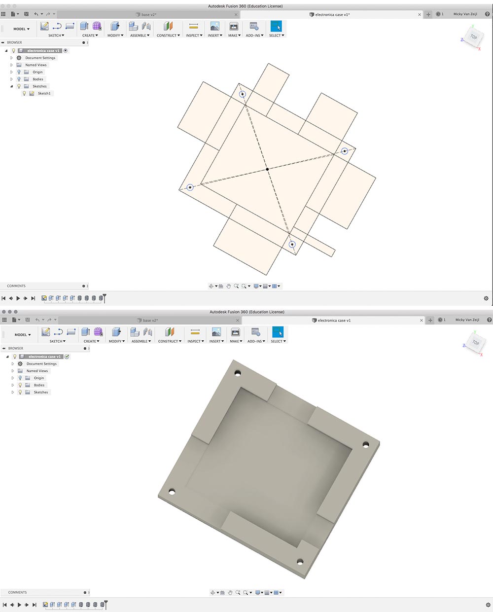 3D design for my Tree-satsha board
As you can see in the video below the tree-satsha board fits nicely within the case. I will mount the case on the back of my base to make sure the board stays safe.
Case for my Tree-Satsha Board
How to make the programming code
I didn’t have the time I wanted and needed for the programming of my code. The design, production and assembly of all the parts took me a lot longer than I had planned. This left me with hardly no time to write a nice program. To make sure I could prove and see that my final project works I wrote an Arduino sketch which combines two example sketches. The capacitive touch and Neopixel strand version. I tweaked these so the Neopixels would respond to the capacitive touch. I also added a more green version of the rainbow function in the strand test, to create a more forest feel to my project. This code can be found in the [documentation of week 20]((http://fabacademy.org/2019/labs/waag/students/mick-vanzeijl/posts/2019/06/05/week20.html)
In the end I did tweak a bit in code after the final presentation as I wanted to show a better proof of concept. It’s still quite simple but at least I have four touch pads working and one of them I can use to switch off the lights.
//Based on the example sketches by Ada Fruit
// CapitiveSense Library Demo Sketch - Paul Badger 2008
// and Neopixel Strand test - A basic everyday NeoPixel strip test program by Adafruit
// Changed by Micky van Zeijl on June 29, 2019

#include <CapacitiveSensor.h>
#include <Adafruit_NeoPixel.h>
#define LED_PIN   3
#define LED_COUNT 4

Adafruit_NeoPixel strip(LED_COUNT, LED_PIN, NEO_GRB + NEO_KHZ800);

CapacitiveSensor   cs_10_7 = CapacitiveSensor(10, 7);       // 1M resistor
CapacitiveSensor   cs_10_9 = CapacitiveSensor(10, 9);       // 1M resistor
CapacitiveSensor   cs_10_6 = CapacitiveSensor(10, 6);       // 1M resistor
CapacitiveSensor   cs_10_5 = CapacitiveSensor(10, 5);       // 10M resistor


void setup()
{
  cs_10_7.set_CS_AutocaL_Millis(0xFFFFFFFF);     // turn off autocalibrate on channel 1 - just as an example
  Serial.begin(9600);

  strip.begin();           // INITIALIZE NeoPixel strip object (REQUIRED)
  strip.show();            // Turn OFF all pixels ASAP
  strip.setBrightness(50); // Set BRIGHTNESS to about 1/5 (max = 255)
}

void loop() {
  long start = millis();
  // arbitrary delay to limit data to serial port

  if (isEffectEnabled(1)) {
    Effect1(strip.Color(0, 255, 0), 0);
    //delay (10);
  }

  else if (isEffectEnabled(2)) {
    Effect2(strip.Color(0, 0, 255), 0);
    //delay (10);
  }

  else if (isEffectEnabled(3)) {
    Effect3(0);
  }

  else if (isEffectEnabled(4)) {
    Effect4(strip.Color(0, 0, 0), 0);
    //delay (10);
  }


}

bool isEffectEnabled (int NR) {
  long total1 =  cs_10_5.capacitiveSensor(30);
  long total2 =  cs_10_6.capacitiveSensor(30);
  long total3 =  cs_10_7.capacitiveSensor(30);
  long total4 =  cs_10_9.capacitiveSensor(30);

  //Serial.print(millis() - start);        // check on performance in milliseconds
  //Serial.print("\t");                    // tab character for debug windown spacing
/*
  Serial.print(total1);                  // print sensor output 1
  Serial.print("\t");
  Serial.print(total2);                  // print sensor output 2
  Serial.print("\t");
  Serial.print(total3);                // print sensor output 3
  Serial.print("\t");
  Serial.println(total4);                // print sensor output 4
  Serial.print("\t");
  //delay(10);
  */

  if (total1 > 800 && NR == 1) {
    return true;
  }

  if (total2 > 400 && NR == 2) {
    return true;
  }

  else if (total3 > 400 && NR == 3) {
    return true;
  }
  else if (total4 > 400 && NR == 4) {
    return true;
  }

  return false;

}

void Effect1(uint32_t color, int wait) {
  for (int i = 0; i < strip.numPixels(); i++) { // For each pixel in strip...
    if (!isEffectEnabled(1)) {
      break;
    }
    strip.setPixelColor(i, color);         //  Set pixel's color (in RAM)
    strip.show();                          //  Update strip to match
    delay(wait);                           //  Pause for a moment
  }
}


void Effect2(uint32_t color, int wait) {
  for (int i = 0; i < strip.numPixels(); i++) { // For each pixel in strip...
    if (!isEffectEnabled(2)) {
      break;
    }
    strip.setPixelColor(i, color);         //  Set pixel's color (in RAM)
    strip.show();                          //  Update strip to match
    delay(wait);                           //  Pause for a moment
  }
}

 //Rainbow cycle along green parts
void Effect3(int wait) {
  for (long firstPixelHue = (65536 / 6); firstPixelHue < 10 * 65536; firstPixelHue += 124) {
      if (!isEffectEnabled(3)) {
        break;
      }
    for (int i = 0; i < strip.numPixels(); i++) { // For each pixel in strip...
      int pixelHue = firstPixelHue + (i * (65536 / 2) / strip.numPixels());
      strip.setPixelColor(i, strip.gamma32(strip.ColorHSV(pixelHue)));
    }
    strip.show(); // Update strip with new contents
    delay(wait);  // Pause for a moment
  }
}

/*
void Effect3(int wait) {
  // Hue of first pixel runs 5 complete loops through the color wheel.
  // Color wheel has a range of 65536 but it's OK if we roll over, so
  // just count from 0 to 5*65536. Adding 256 to firstPixelHue each time
  // means we'll make 5*65536/256 = 1280 passes through this outer loop:
  for(long firstPixelHue = 0; firstPixelHue < 5*65536; firstPixelHue += 256) {
   if (!isEffectEnabled(3)) {
       break;
      }
    for(int i=0; i<strip.numPixels(); i++) { // For each pixel in strip...
      // Offset pixel hue by an amount to make one full revolution of the
      // color wheel (range of 65536) along the length of the strip
      // (strip.numPixels() steps):
      int pixelHue = firstPixelHue + (i * 65536L / strip.numPixels());
      // strip.ColorHSV() can take 1 or 3 arguments: a hue (0 to 65535) or
      // optionally add saturation and value (brightness) (each 0 to 255).
      // Here we're using just the single-argument hue variant. The result
      // is passed through strip.gamma32() to provide 'truer' colors
      // before assigning to each pixel:
      strip.setPixelColor(i, strip.gamma32(strip.ColorHSV(pixelHue)));
    }
    strip.show(); // Update strip with new contents
    delay(wait);  // Pause for a moment
  }
}


 */


void Effect4(uint32_t color, int wait) {
  for (int i = 0; i < strip.numPixels(); i++) { // For each pixel in strip...
   // if (!isEffectEnabled(4)) {
    //  break;
   // }
    strip.setPixelColor(i, color);         //  Set pixel's color (in RAM)
    strip.show();                          //  Update strip to match
    delay(wait);                           //  Pause for a moment
  }
}
Final result
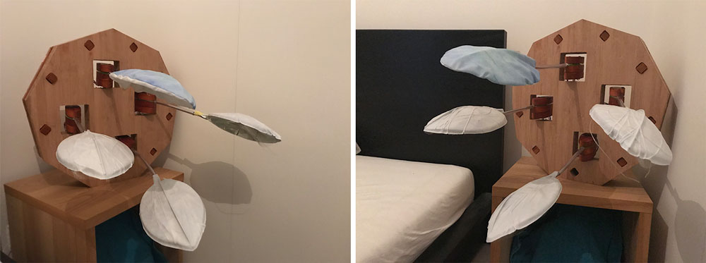 End result without lights
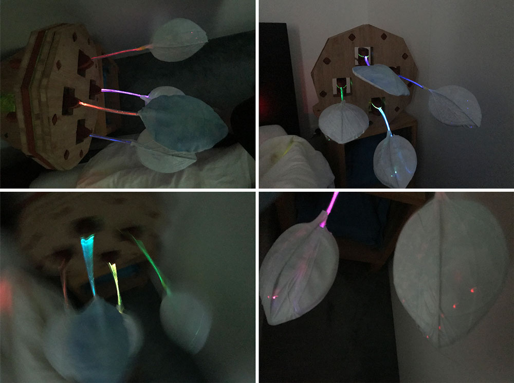 End result with lights
Leaves light up
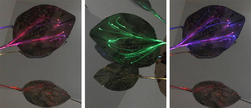 End result detail leaves
End result detail connector and leaf
What do I want to add and improve
There was not enough time to finish my project the way I would like. Once my project was put together I wasn’t that satisfied because I could see how many things I would change and didn’t turn out the way I wanted. Therefore I have a lot of things I would like to add and/or change. I will describe them for each part.
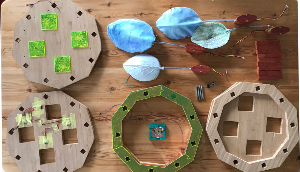 Main parts final project
The leaves
- I decided to create four more bigger leaves. However it would be a lot nicer to have more smaller leaves or to add a more tree like structure to the leaves I have at the moment.
- The optical fibers work nicely. I would like to add some extra light to each leaf as well, because at the moment you can only really see the effect when it’s really dark.
- I’m not happy with the way the leaf is not connected with ‘the connector’. The brass rod and the optical fibers inside of the tube kind of works but it looks funny I think. Next step would be to fine tune this design. Think of different ways to make this connection.
- The tulle works kind of okay for the optical fibers. However it’s still quite difficult to get the fibers in place. I would like to create a more vein like leaf structure. Which wasn’t possible at the moment. I think for this a mold would be best.
- I would like to change the finish of my leaves. The UV-print had a nice effect but the top part isn’t that beautiful. I created the fabric covers for this. And these help but than the print is not as visible. So I would try to find a way to add the covers on top. Or to create a different type of leaf.
The connector
- At the moment there’s a bit of movement in the leaves because of the bearings in the connector. Next step would be to make this much more a pendulum with springs. And maybe a motor if there’s a really silent one. Would be nice to have a more continues movement.
- The connector is quite big at the moment, this also due to the thickness of the wood. This makes it really solid but it also makes it more difficult to add more leaves. So or I will add branches to each connector or I should find a way to make them smaller. Or at least less thick.
The base
- I didn’t connect all the parts of the base yet because it’s nice to see the inside. But also because it’s difficult in the design I have a the moment to be able to debug or change parts when they’re broken. You are able to open it but you have to remove all the parts for it. I would like to add something that make it a lot easier to change parts.
- The base is quite robust, this also because of the thickness of the wood and the size of the connectors. I would like to make a version which is a bit more subtle.
- My original idea for the final project was much more organic than my final version. I would still like to experiment with these sort of shapes.
The electronics
I’m quite happy with the electronics design what I might add in the future is maybe a very silent motor or another system to start the movement of the leaves. If I would make this for production I wouldn’t use the Satsha board because it has a lot more functionality than I need at the moment. So an improvement would be to make the board smaller with only the parts I need: capacitive touch and Neopixel connection.
The programming
I didn’t have time for the programming part of my final project. I made a very simple sketch that works with the capacitive touch and the Neopixel. However I wanted to add a lot more functionalities.
- fine tune and design the light effects of the Neopixels
- Changing intensity of the lights
- Adding a timer, so when you fall in sleep the lights slowly go out
- Option to choose different themes like the seasons or day and night.
- More clear interaction with turning it on or off.
What makes me proud
What made most proud with this final project is the 3D-printed connector between the Neopixel and the optical fiber. I had no experience with 3D design before I started the Fab Academy and I’m really proud that I managed to 3D design a functional block that works nicely and precise. It fits 14 optical fibers perfectly with the light beam of the Neopixel. The bottom part clicks nicely to the top. Plus there’s space for the wires on each side of the Neopixel.
The electronic part made me proud as well because I had zero experience with electronics before I started the Fab Academy. I used the basic Satsha kit but added my own parts and I decided to make sure I could always add extra parts by adding headers to empty pins. This part worked straight away with no problem, which still surprises me.
Overall I’m most proud that for my final project I used about all the machine that could be used. My aim for joining the Fab academy was to learn how to make stuff. For my final project I really wanted to use different techniques, skills and machines.
Credits and thanks
Klaas-jan helped out a lot to finish my final project on time so I really want to thank him for all his time and patience. In addition I want to thank my Fab academy group: Anne, Rutger, Joey and off course instructor Henk. We had a lot of fun together and helped each other through the last weeks to be able to finish on time. I also want to thank Sander, Henk and Cees of the Makerslab at the Amsterdam University of Applied Sciences for their advise as well as my colleagues at the University (especially Maaike en Irma) for their help with my daily work. My parents for their advise about springs, optical fibers, sewing tips and their enthusiasm. My friends for their support, Sandra thanks for the video editing lessons and Annemieke for all the inspiration and advise. It was a fabulous adventure!