
What will it do?
My project Kalakar is an Omni wheeled 4WD CNC Drawbot. Its a portable pen plotter that reads Gcode Send Via bluetooth and draw complex patterns in various surfaces.
Who will use it?
Kalakar is a device that caters for all ages, and may appeal particularly to those who enjoy being creative with pen and ink.
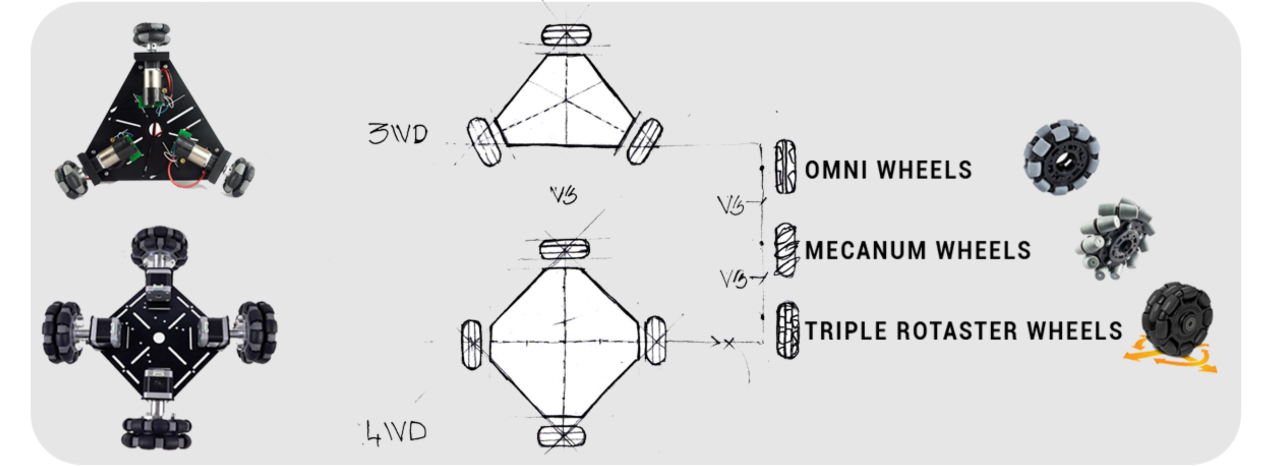
Drive system
Connectivity

Conceptualization
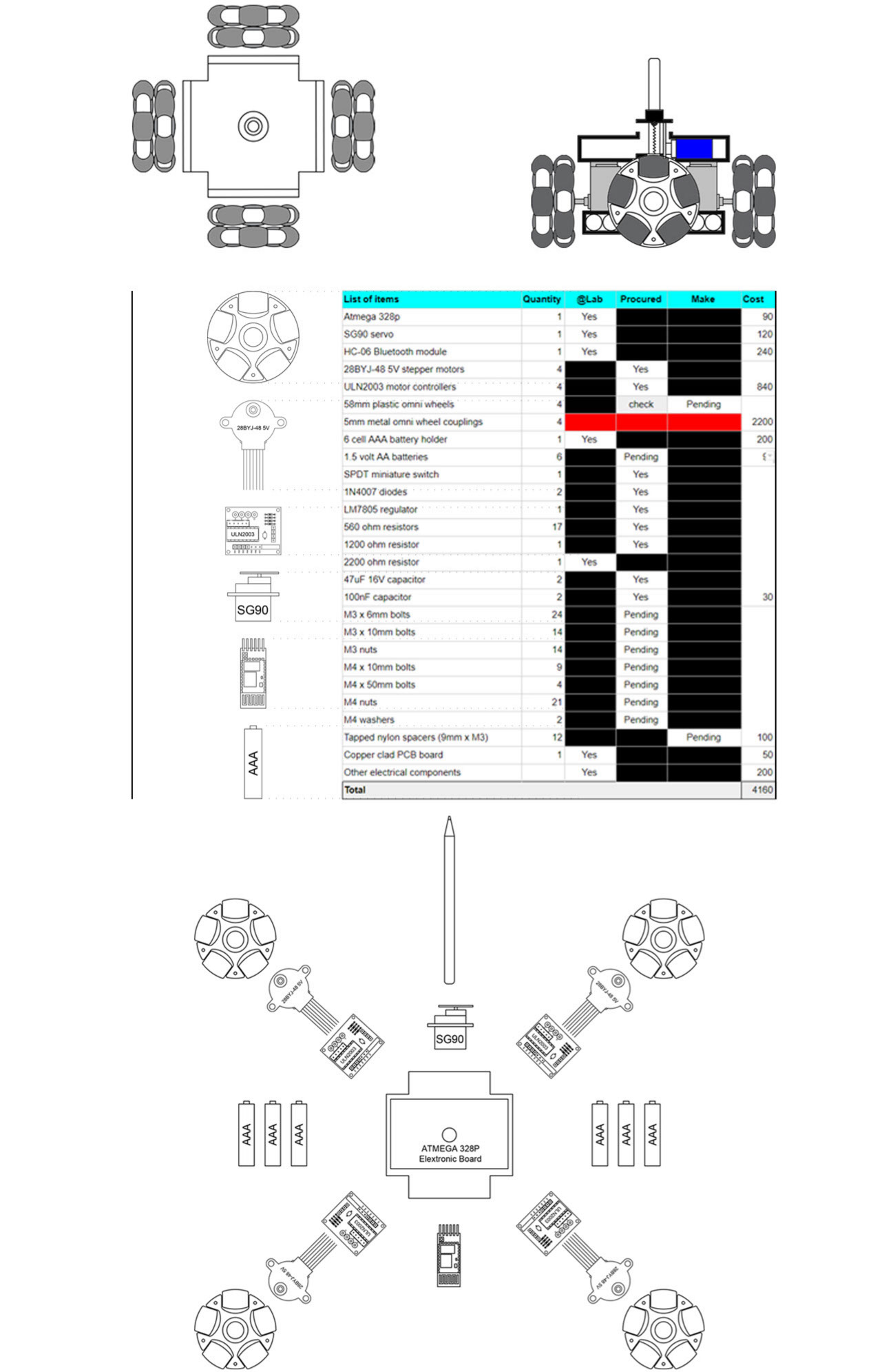
Bill of Materials
Assemble Plan
Theory
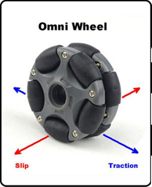
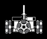
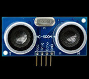
Omni-wheels (Pic 1) only have traction in the direction of rotation. Any oblique force causes the wheel to move sideways.
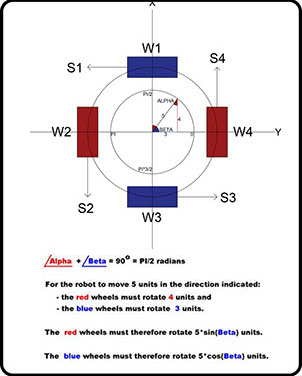
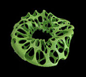
Movement in any direction is possible if we place omni-wheels along the X-axis and Y-axis as shown in (Pic 2).
The omni-wheel arrangement (Pic 2) is ideally suited to Bresenham’s line drawing algorithm.
The design for this plotter was inspired by the following article http://modwg.co.uk/wp-content/uploads/2015/06/Omni... which explains how to construct 3, 4, 6, and 8 wheeled omni-bots.
The wheel arrangement, which differs from that in the above article, offers the following advantages:
- The wheels are ideally positioned for XY plotting.
- No tyre scrubbing
- Simpler calculations
- Simpler electronics
Kinematics
This step derives the forward, and inverse, kinematic equations for my Project.
Assumptions
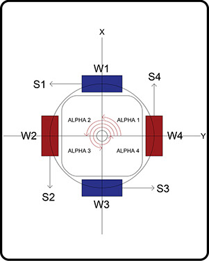
The robot X-axis lies along W2, W4.
The robot Y-axis lies along W1, W3.
Normal rotation is clockwise looking towards the robot center.
Omni wheels (Pic 3) only have traction in the ‘S’ directions.
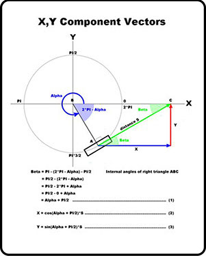
The ‘x’ and ‘y’ vector components for any given wheel are derived in Pic 4.
For the four-wheel robot shown in Pic 3 the ‘x’ and ‘y’ vector components are:
x1 = cos(Alpha 1 + PI/2)*S1 = cos(90 + 90)* S1 = cos(180)*S1
x2 = cos(Alpha 2 + PI/2)*S1 = cos(180 + 90)* S1 = cos(270)*S2
x3 = cos(Alpha 3 + PI/2)*S1 = cos(270 + 90)*S1 = cos(360)*S3
x4 = cos(Alpha 4 + PI/2)*S1 = cos(360 + 90)*S1 = cos(450)*S4
y1 = sin(Alpha 1 + PI/2)*S1 = sin(90 + 90)* S1 = sin(180)*S1
y2 = sin(Alpha 2 + PI/2)*S1 = sin(180 + 90)* S1 = sin(270)*S2
y3 = sin(Alpha 3 + PI/2)*S1 = sin(270 + 90)*S1 = sin(360)*S3
y4 = sin(Alpha 4 + PI/2)*S1 = sin(360 + 90)*S1 = sin(450)*S4
The resultant vectors for this robot are:
x = x1 + x2 + x3 + x4
y = y1 + y2 + y3 + y4
There is also an angular rotational component "w" which enables the robot to spin about its Z-axis:
w= s1 + s2 + s3 + s4
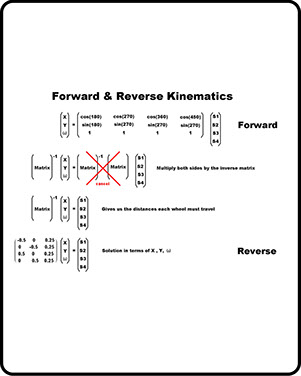
Forward kinematics
Pic 5 shows the above equations written in matrix form.
The “forward” equations are not particularly useful as they calculate where the robot will be after the wheels have finished rotating.
Reverse kinematics
What we want are the “reverse” equations as these allow us to calculate how much each wheel must rotate for the robot to reach a given (X,Y) coordinate.
These equations also enable us to simultaneously rotate the robot body.
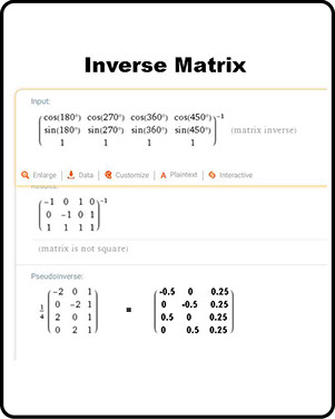
Calculating the “inverse matrix”
There are several methods for obtaining the “inverse” of a matrix.
The “Gauss-Jordan” technique, using “identity” matrices, is perhaps the simplest of the manual methods. A video demonstrating this technique may be found at https://www.youtube.com/watch?v=cJg2AuSFdjw
Another way is to use an online “inverse matrix calculator” such as that found at https://www.wolframalpha.com/input/?i=calculate+in...
This calculator requires that the matrix information be entered in the following format:
{{cos(180),cos(270),cos(360),cos(450)},{sin(180),sin(270),sin(360),sin(450)},{1,1,1,1}}
Pic 6 shows the output when you click "compute".
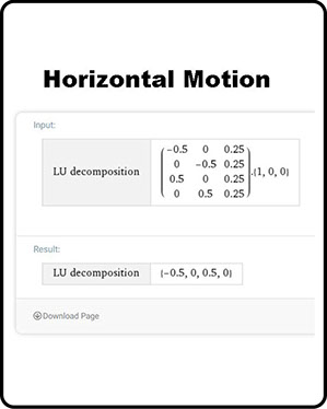
Horizontal motion
The relative wheel speeds for horizontal motion may be found by plugging the following equation into the online “matrix calculator” at https://www.wolframalpha.com/input/?i=matrix+calc...
Substituting {x,y,w} = {1,0,0} in the reverse kinematics formula:
{S1,S2,S3,S4} = {{-0.5,0,0.25},{0,-0.5,0.25},{0.5,0,0.25},{0,0.5,0.25}}*{1,0,0}
{S1,S2,S3,S4} = {-0.5,0,0.5,0}
The results are shown in Pic7. A negative sign indicates CCW rotation.
Wheel W1 rotates CCW ... wheel W3 rotates CW.
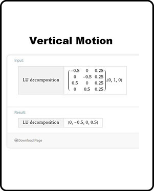
Vertical motion
The relative wheel speeds for vertical motion may be found by plugging the following equation into the online “matrix calculator” at https://www.wolframalpha.com/input/?i=matrix+calc...
Substituting {x,y,w} = {0,1,0} in the reverse kinematics formula:
{S1,S2,S3,S4} = {{-0.5,0,0.25},{0,-0.5,0.25},{0.5,0,0.25},{0,0.5,0.25}}*{0,1,0}
{S1,S2,S3,S4} = {0,-0.5,0,0.5}
The results are shown in Pic 8. A negative sign indicates CCW rotation.
Wheel W2 rotates CCW ... wheel W4 rotates CW.
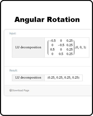
Angular motion
This feature is not required in this plotter since we are using Bresenham’s line formula which only requires horizontal and vertical movement.
The relative wheel speeds for angular motion may be found by plugging the following equation into the online “matrix calculator” at https://www.wolframalpha.com/input/?i=matrix+calc...
Substituting {x,y,w} = {0,0,1} in the reverse kinematics formula:
{S1,S2,S3,S4} = {{-0.5,0,0.25},{0,-0.5,0.25},{0.5,0,0.25},{0,0.5,0.25}}*{0,0,1}
{S1,S2,S3,S4} = {0.25,0.25,0.25,0.25}
The results are shown in Pic 9. A negative sign indicates CCW rotation.
All wheels rotate in the same direction.
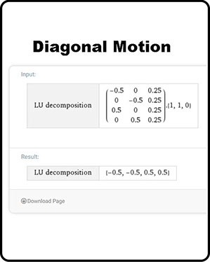
Diagonal motion
This feature is not required in this plotter since we are using Bresenham’s line formula which only requires horizontal and vertical movement.
The relative wheel speeds for vertical motion may be found by plugging the following equation into the online “matrix calculator” at https://www.wolframalpha.com/input/?i=matrix+calc...
Substituting {x,y,w} = {1,1,0} in the reverse kinematics formula:
{S1,S2,S3,S4} = {{-0.5,0,0.25},{0,-0.5,0.25},{0.5,0,0.25},{0,0.5,0.25}}*{1,1,0}
{S1,S2,S3,S4} = {-0.5,-0.5,0.5,0.5}
The results are shown in Pic 10. A negative sign indicates CCW rotation.
Wheels W1 and W2 rotate CCW ... wheels W3 and W4 rotate CW.
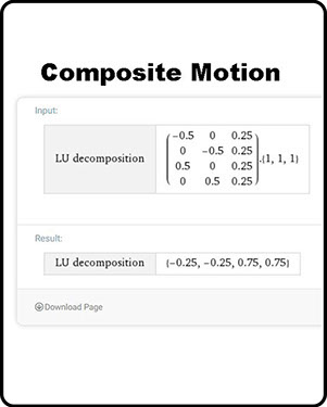
Composite motion
This feature is not required in this plotter since we are using Bresenham’s line formula which only requires horizontal and vertical movement.
It is possible to combine angular and diagonal motion by varying the {x,y,w} parameters.
The relative wheel speeds for combined diagonal and angular motion may be found by plugging the following equation into the online “matrix calculator” at https://www.wolframalpha.com/input/?i=matrix+calc...
Substituting {x,y,w} = {1,1,1} in the reverse kinematics formula:
{S1,S2,S3,S4} = {{-0.5,0,0.25},{0,-0.5,0.25},{0.5,0,0.25},{0,0.5,0.25}}*{1,1,1}
{S1,S2,S3,S4} = {-0.25,-0.25,0.75,0.75}
The results are shown in Pic 11. A negative sign indicates CCW rotation.
The relative wheel speeds in this example cause the body to rotate as the plotter moves diagonally.
Source: https://www.instructables.com/id/Omni-Wheel-CNC-Plotter/
Have you?
Yes, I have sketched my final project idea/s.
Yes, I have described what it will do and who will use it.