Last changes
Version 5.0
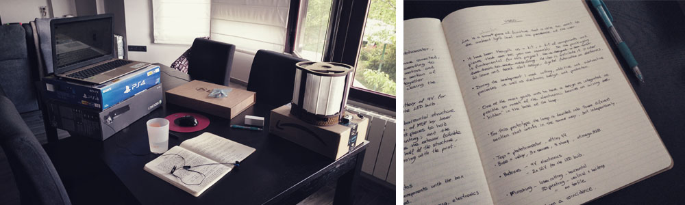
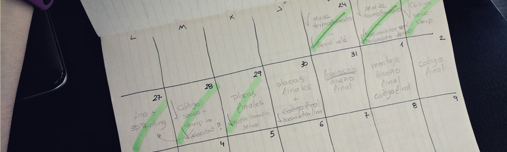
Two weeks more and we are over!! I'm getting nervous and there is still a lot of things to get finished!! So the first thing that I wanted to do is to plan the time very well: the presentation is on Jun 12th; my idea is to finish the project on Jun 4th or 5th, so I have one week more for making the final slice and video, documenting, and some time if something needs to be finished.
I started this next steep of the final project development doing the communication between the servo motor and the SHARP distance sensor. I took as a reference the codes that I did in the networking and communications week, an the Julian Ocampo's output devices assigment.
Fortunately and surprisingly, everything works pretty well from the beginning. I used the fabkit to test the code. One of the things that gave me some problems was how to control the speed of the servo motor, as by default it moves too fast for my purpose. So I looked for a way of modifying that speed through the code (I also found some tutorials that explain how to change the speed opening the servo's housing and touching the potentiometer that this kind of motors has inside.) Finally, I got to this webpage that explains how to use a modified servo library, VarSpeedServo, that gives you the possibility to control the speed of a servo motor if you connect it to a PWM pin.
So I download the library and I installed it in Arduino IDE, from sketch > include library > add .ZIP library, and it worked very well!! Here is the code:
On the other hand, after the wildcard week, I decided to change the material of the exterior foldable layer. From now on, I'm going to use linen with the structure made by 3d printing. I think this will more interesting rather than having paper. This change of materiality means that I have to redesign a bit the shape of the vertical structure of the lamp. Here you can see how it looks like (while the above code running):
Final fabrication
From this point, I finally started designing and fabricating the final version of the lamp, the prototype that I will present in the final.
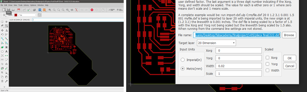
I decided to start with the main PCB of the project. I modified the file that I did for the fabkit, organizing the connections based on the distribution of the different devices in the base of the lamp, and keeping also in mind the type of pin that they need (digital for the relay and analog for the servos and distance sensors). On the left I placed the relay and the servo motor connections, as they share the same combination of wires (GND, VCC, SIGNAL); in the right I put the distance sensors, which have other combination of wires (SIGNAL, GND, VCC); and in the left bottom corner I placed a 2x2 pin header for the serial bus networking to the PCB of the phototransistor. Finally I added the regulator for 5V to be able to power up the system with a battery of 9V.
As space was limited, I wanted to be sure that the PCB fits in the base, so in Eagle, I imported the outline vector of the space that I had for the PCB. I got this vector in Rhino, the software that I used to build my 3D digital model, and then from file > import > dxf I chose my file. Then I selected as the target layer > dimension.
One important note here: the outline vector has to be in the 0,0 of the reference plane in Rhino, otherwise, if it is very far away from it, when you try to import it, Eagle will tell you that the workspace is not big enough. That happened to me three times until I understood where the problem was.
After editing some things in Photoshop, such as removing the three footprints that I didn't need in the top right corner and adding the logo of the lamp, I milled the PCB without incidents.
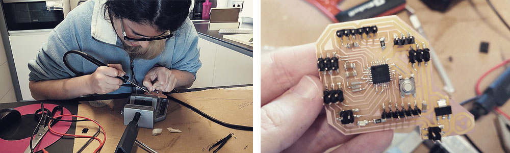
This time was quite hard to solder the Atmega328. When I went to solder the first pin, I soldered three pins at the same time, so I had the three of them connected with tin, and it was extremely hard to cut the connexion. I forgot to bring from the lab the hot air gun, so I had to use the soldering pen and a tiny cutter to remove the tin in between of the pins. And that happened to me twice more (I think the tip of the soldering pen was overused so it wasn't working properly). But finally, I could finish soldering all the components. I tested out the connections with the multimeter and I checked that everything was good.
(Thank God...)
Then I designed the covers for the edges of the base, as until this moment I hadn't think about it. I wanted to use the laser cutter to fabricate it and, as the perimeter of the lamp is circular, I did the design based on the living hinges technique so I decided to use a similar pattern than I applied for the computer-controlled machining assignment. I made five or six pieces before getting the good one.
After including the name of the lamp and my name to be engraved on one of the empty parts of the base (where there are no footprints of any component), I cut the rest of the pieces.
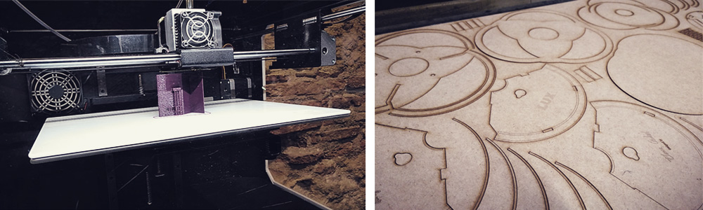
And, at the same time, I 3D printed the vertical structure and the different holding pieces for the exterior foldable layer and the electronics.
I wasn't sure about the appearance of the laser cut pieces, with those burned areas... So I decided to paint them matte black. So after gluing, I turned on the ventilation system of the paint booth and I spray painted all the pieces in black. They looked great.
However, when I assembled all these new pieces, the lamp looked horrible, very ugly in my opinión. The black was too black, it didn't combine well with the purple of the 3D printed pieces and either with any of the different textiles of different colors that I had... But the worst part was that now, due to the paint, the pieces were bigger and thicker, so all the joints and measurements didn't fit so well as before...
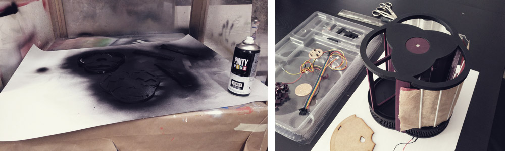
So I decided to keep the original color of the MDF. And that means that I had to cut all the pieces again... and glue them again... But one good thing about not painting them is that it is very easy to recognize how it has been fabricated, there is no doubt when you see those burned areas, however, with the pieces printed in back it is not so easy to identify how they were made.
But I took advantage of the fact that I had to re-cut the pieces and I made some tiny modifications in the design and I added the footprint of the main PCB in the base, so the system would be even more integrated and organized.
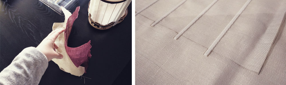
After cutting the pieces again I fabricated the exterior foldable layer following the technique that I used in the wildcard week. Fortunately, I could get four different types of linen (white, cream, brown and burgundy), so I could try which one filters better the light, and I even fabricated a two-layer piece, to know how it works. This last one was too thick, it filtered too much light and I could notice that the servo suffers a bit while folding it. Finally, I decided to use the cream one, as is the one that filtered enough light to have a nice and warm ambient light when is closed and is light to be folded by the servo without problems.
I also did a template to cut the outline with the laser cutter, as cutting it with scissors was very imprecise, besides that the fabric starts to fray. Cutting it with the laser cutter you avoid that, as you burn the edges keeping perfect the shape and outline. (Before cutting I engraved the template on a paper to know where to place the linen on the bed of the laser cutter).
It is very satisfying... XD
Final code
I was really excited (and nervous) about trying how the system works with the battery. So, after burned the bootloader for the first time, I checked with the above code if the battery of 9V was able to run at least one servo with one distance sensor. And it did!!
Then I placed all components and wires in the base, trying to have everything as organized as possible and I went further with the code. This time I wanted to have the 3 servos and the 3 distance sensors working at the same time. And after some small adjustments in the code, it worked!
And finally, I included the serial bus network in the code and connected the relay and the PCB of the phototransistor to the main PCB. And everything worked very well, except for the fact that servomotors move suddenly and randomly from time to time, they have like little spasms (You can see that in the video below). And these spasms occur more often the more consumption I have, I mean, if together with the phototransistor PCB only one servo+sensor is working, then the spasms are almost negligible, but if I have the 3 motors+sensors the spasms occur more often.
My instructor and I were looking for possible solutions and we tried some things such as avoid position 0 and 180 of the servo, but nothing worked. I wasn't able to fix it for the final, but I think that the problem is the consumption that I have, I think is too much. And the serial networking also takes a lot. My first idea to solve this would be to get a battery and regulator with more amperage. Then I also would try to add some capacitor to filter the signal and finally, I would like to separate into two the main PCB and the part where the battery is attached, I think that also will help.
Even with that issue, I think the system works very well, I have never thought to be able to reach this point, so I'm happy.
Final preparations for the final presentation
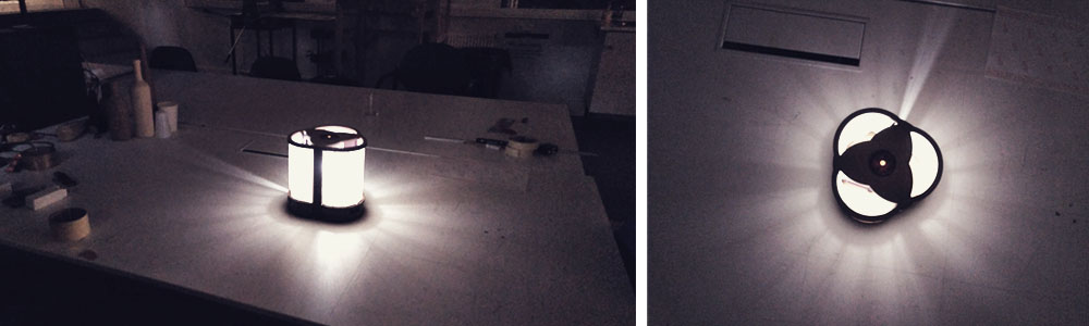
With the code working, I just had to assemble the lamp and check if the lamp worked. And fortunately it did, I didn't need to do more adjustments, so now it was time to prepare everything for the final presentation.
Altought during the fabrication process I recorded videos thinking of at this moment, there were some videos that I also wanted to record such us the assembly process and a "demo" of how the lamp works in a real situation.
A very special moment for me, personally, was when I power up the lamp, fully assembled and programmed, I turned off the light of the room and then the lamp started working. I was so focused on the different parts and details that until that moment I didn't realize that I had achieved to make a very nice and fully operational project. It was very emotive to see how the system worked and how beautiful the effect of the light was. Six months ago I had no idea at all about electronics or programming and now, thanks to the Fab Academy, I have learned the necessary skills to develop things like this one. I feel very proud of myself.
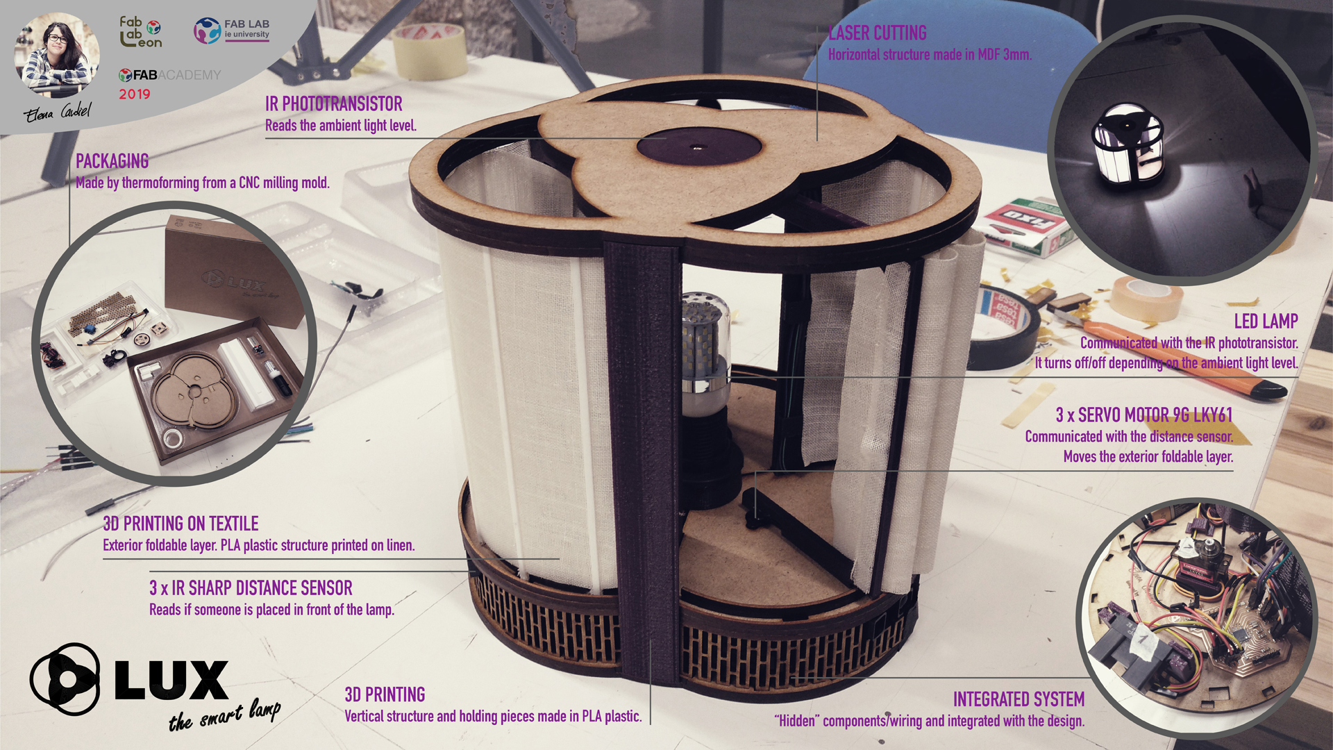
After that, I made the final slide and video. For the slide, I improved the one that I did for the Invention, intellectual property, and income week, including more information.
For the video, I did a selection of all the videos that I had done during these last two months and I made the composition with VideoPad. The idea was to show at the beginning of the video how the lamp works, then to show the packaging as I think is an interesting part of the project (and not usual to see) and then to show how it has been made: the fabrication and assembly. I also added music to accompany the images and finally, I included some texts, but just the "titles" of each part of the video, as I think that the video was able to explain the rest by itself.
The day before of the final presentation I wrote the "speech" and I set up the room to be ready to present and for a live demo.