Computer-controlled machining
Week 08
Like every week I started the week planning the assignment.
Group assignment. Characterizing the machines
I am a remote student and none of my colleagues are in the fab academy, so I did this part of the assigment individualy.
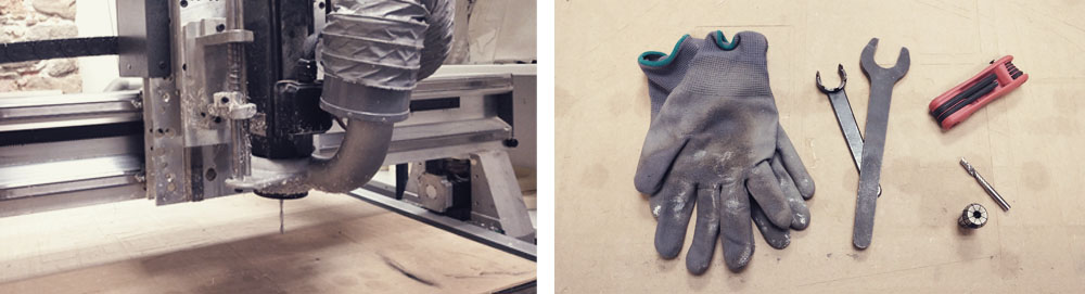
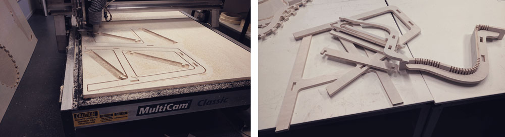
The CNC milling machine that we have in our Fab Lab is a MultiCam Classic with a maximum working surface of 1220x2440mm. To fix the material to the CNC's bed the machine uses a vacuum bomb.
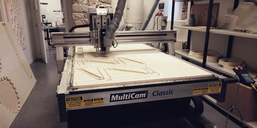
I think the vacuum bomb is the best option to fix the material. Thanks to it you don't need to screw or use clamps. It is very comfortable, saves time and material and makes the process much easier because you don't have to worry about avoiding clamps or screws during the milling process.
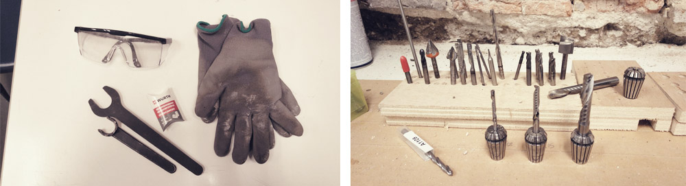
This machine can be very dangerous if you don't take the necessary security measures. You always have to wear safety gloves and glasses, and hearing protection, such us ear buffers, while operating with the machine.
On the other hand, depending on the kind of material, the thickness of the material, and the type of job (roughing, finishing, cutting, engraving) you have to use a specific milling bit. And these tools are different according to their length, cut length, thickness, number of flutes and end (flat/ball/conic). That's why if you want to make the most of your CNC you need to have a lot of different milling bits.
For this assignment, I decided to use plywood of 15mm. and a milling bit of Ø6mm (length 60mm.; cut length 32mm.; 1 flute ). Before cutting my design I did some tests to check the limits of the material and machine. Then I could find out that the alignment was good however, I lose a half of millimeter in the x-axis (my file was 100x100mm. but the cut piece had 100x99,5mm.), but I only had this issue for exterior vectors, for interior vectors the size was perfect (50x50mm., same as in the file.).
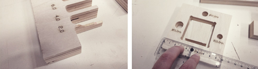
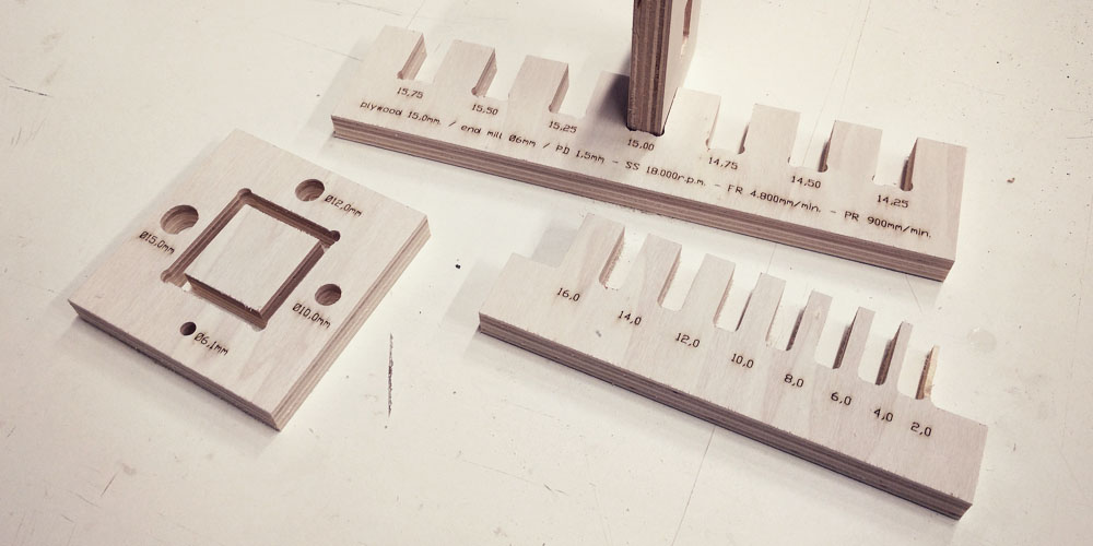
It is amazing the grade of precision that the CNC has, considering the size of the machine and milling bits. For me that difference of 0,5mm it totally acceptable!!.
Design
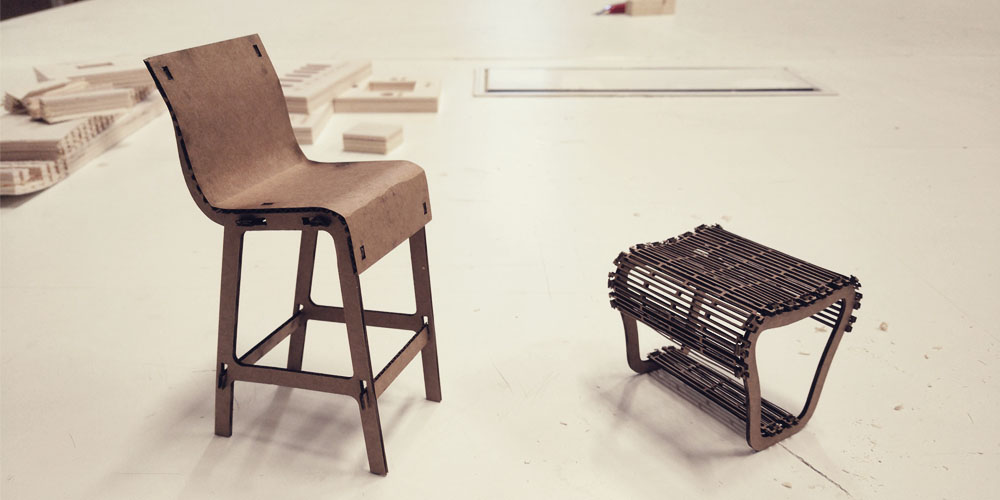
Before taking the computer I did some sketches on my notebook. I wanted to do two different pieces of furniture for the Fab Lab, a low stool and a tall chair. For this assignment I wanted to try two techniques to bend wood (living hinges and kerfing), as well as different kind of joinery.
Then I opened Rhinoceros 3D and I started to digitize my drawings adding real measurements. I worked in 2D and 3D at the same time until to get the final vectors for the CNC.
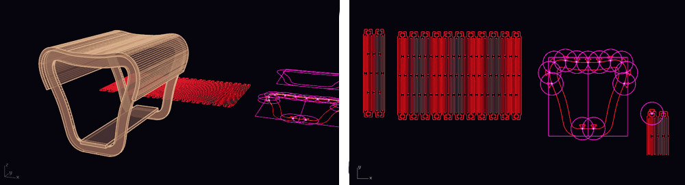
> First design: Low stool
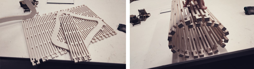
For this piece of furniture, I wanted to use the living hinges technique, which consists in creating a pattern that allows a rigid piece to bend along the line of the hinge. It is necessary here to find a balance between the material that you leave and the material that you remove. More free space between the lines of the pattern usually means higher curvature, but if the thickness of your pattern is too thin your piece could break easily. I decided to use 9mm. for both space and material.
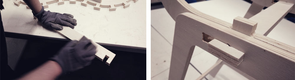
A part from that, I needed to find a way to put together the pattern and the ribs of the stool. I didn't want to use white glue so I decided to use a "clamp" system: to fit the pattern to the ribs, you have to force and open the end of the living hinge, put the T-tip added to the ribs in and then loose it, and the living hinge by itself will close and hold the T-tip of the rib. Like this, the pattern will take the curved shape of the rib of the stool.
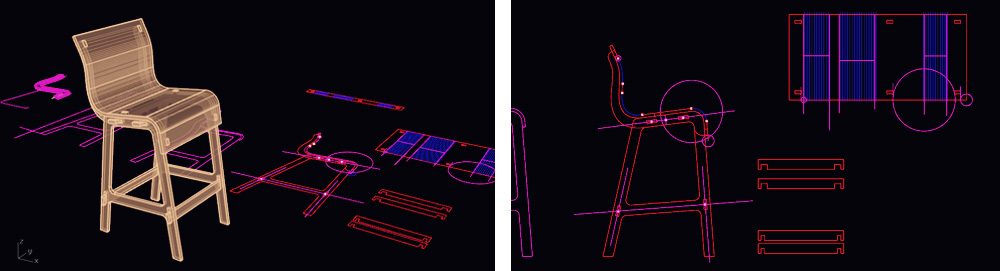
> Second design: Tall chair
For this piece of furniture, I wanted to apply the kerfing technique. Kerf bending is the process of cutting a number of slots into a piece of material that allows it to bend. Essentially, by kerfing the part, you are making it thinner, so it can be flexed to follow a curve. The trick here is to cut most of the way through the material to allow it to bend, but not so much that it becomes too fragile. We have to keep the kerfs close together and regularly spaced so that the bend is smooth and regular with no flat spots.
In this case, we have to take into account the direction of the wood grain, as the wood only can bend in favor of the grain, so our cuts need to be done against the grain. If you try to bend it against the grain it will break.
> Final vectors
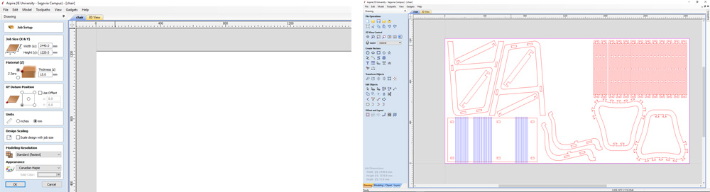
When I was happy with my design I got the final vectors for the CNC and I arranged all the pieces in a plywood board of 1220x2440mm. trying to save as much material as possible.
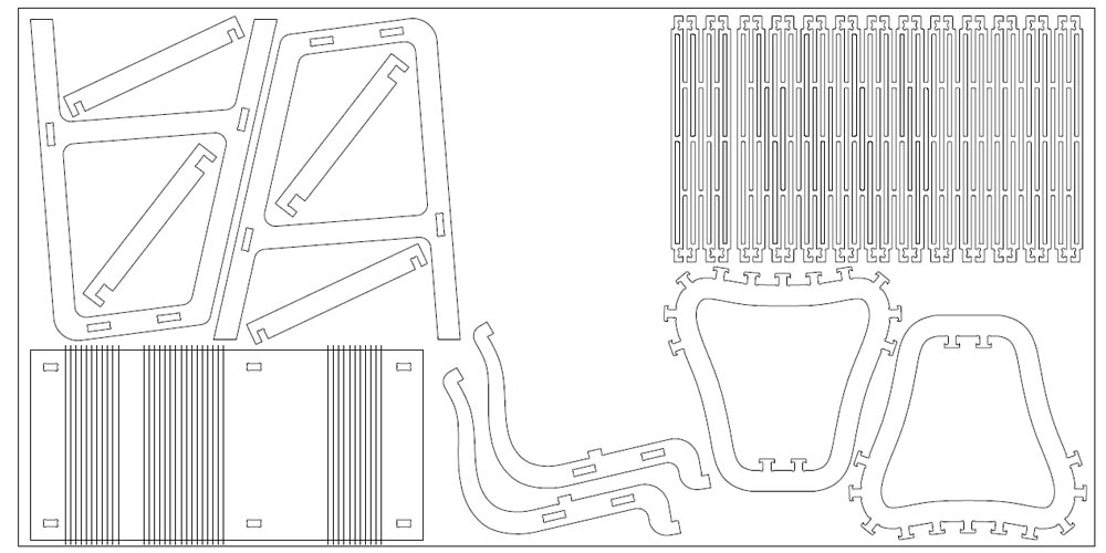
While generating the final vectors I kept in mind that I have to leave a bit of extra space (0,25mm.) for the joints and I added the "dog bones" in the internal corners, so that the pieces can fit perfectly.
But before sending it to the CNC I made a small prototype with the laser cutter to check that the design and files were well done.
Milling software: Aspire
The software that we use in my Fab Lab to prepare the files for the CNC is Aspire, version 8.024
The first thing that I did was to create a new file with the size and thickness of my board of plywood. Then I went to file>import>import vectors and I opened the vectors from Rhinoceros that I previously saved into .dxf format.
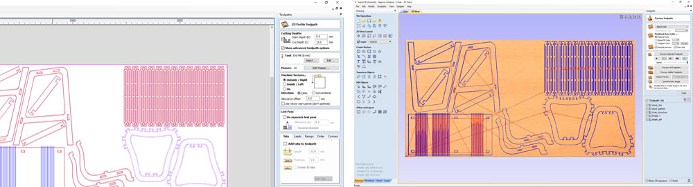
Then, from the "toolpaths bar", I created the toolpath for the outline cutting of the different pieces. I divided the file into several jobs so I can save and send each job independently and have more control over the cutting process.
To calculate the feed rate that I should use I took this webpage as a reference. When calculating the feed rate for any material the chip load is one of the most important factors to be taken into account because the chip load determines the amount of material that each tooth will remove. Another factor that affects chip load is the diameter of the cutter: a larger cutter will be able to handle a larger chip load.
Feed rate = Nº flutes x Chip load x RPM
Based on this mathematical equation, as RPM increases, feed rate will also increase if all other settings remain the same. If the number of cutting edges changes, however, the feed rate will either increase or decrease depending on whether the number goes up or down. The same applies to chip load if the recommended chip load is 0.1 mm/tooth the RPM, feed or number of cutting edges may go up or down to maintain the required chip load. Therefore if the chip load remains the same, and feed rate increases, either the RPM and or the number of cutting edges must increase to maintain the recommended chip load. At the end of this webpage you can see the typical chip load values for various size end-mills and materials.
Another factor is depth of cut. Pass depth will effect edge finish as well as tool life. You will have to adjust your depth to achieve the desired results depending on the type of material and size of cutter. Usually a depth of cut that equals the radius of the cutter is a good starting point.
I decided to used an end-mill of 6mm of 1 flute. The material that I used was plywood of 15mm, so the recommended chip load for that end-mill and material is 0.28 - 0.33. For the spindle speed, I used 18.000 r.p.m.
Feed rate = 1 x 0,28 mm/r.p. x 18.000 r.p.min = 5.040 mm/min
These are the final settings that I used:
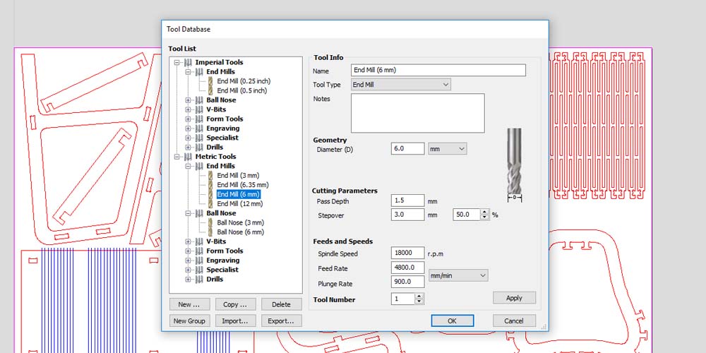
As you can see in the image I set 1,5mm. for the pass depth. I tried first with 2,5mm. but the machine started doing a very loud and deep noise. I didn't like that noise so I stopped the machine and I change the end-mill settings. I didn't want to reduce even more the speed so I decided to use 1,5 for the pass depth. It definitely would take a longer time but in this way the sound of the machine was normal.
Aspire gives you an estimation of time and also allows you to watch a preview of the different toolpaths. In that way, you can know how the machine is going to move over the material and cut your file before sending it. This is a very useful way to check that you have set everything good.
CNC milling
Before sending the file to cut I changed the end-mill for the one that I chose in the Aspire settings. The machine is not able to identify which end-mill is placed in the collet, so you have to pay attention to that, otherwise, if you use a different end-mill to the one in the settings, you can damage the material and break the end-mill.
In my case, to change the end-mill, I need first to take off the attachment for the vacuum.
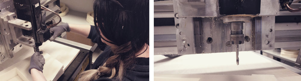
After that, using the control of the machine, I set the xy-zero and I took the z-zero and the max. depth of my material with the sensor.
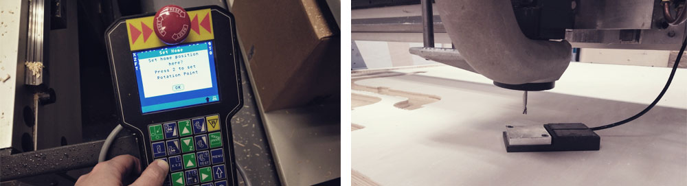
Then, from Aspire I saved the toolpaths as .cnc format in the dncfile folder of the computer and using the control again I sent the file to cut. (We have a network to connect the computer and the CNC, so the CNC is able to read the dncfiles folder of the computer, that is where we save the .cnc files.)
Final results
> Low stool
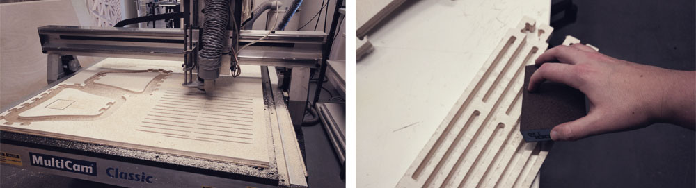
The milling process went good. It took around 3 hours to cut the two ribs and the two patterns (living hinges surfaces). Then, I sanded a bit the edges (I didn't need to sand them too much because the quality of the cut was pretty good) and I assembled all the pieces.
At the beginning, it was a bit hard to open the "clamp joint". I didn't expect that I would need to use so much force and I also was afraid to break the pieces, however, the wood/living hinges behaved very well and once I figure out the best way to do it (which was to put in first one side, then force and open the "clamp joint" and then put in the other side), it only took 10 minutes to assemble the whole stool.
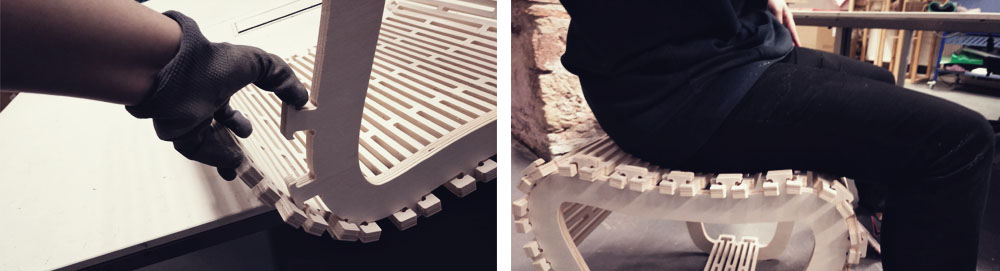
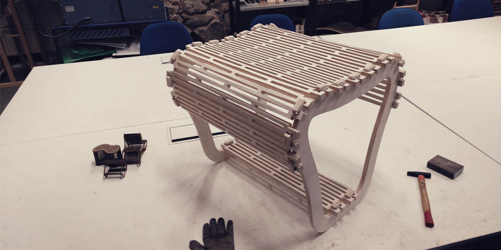
Once everything was assembled, I could check that the stool is very comfortable and strong. It is a bit unstable because of the curves in the base of the ribs, but that is very easy to solve by changing that part of the design. But the most import part that is the living hinges works very well.
> Tall chair
The milling process went pretty well. I cut first the ribs of the chair and then I did some tests to know how deep I could reach for the kerfing without breaking the material.
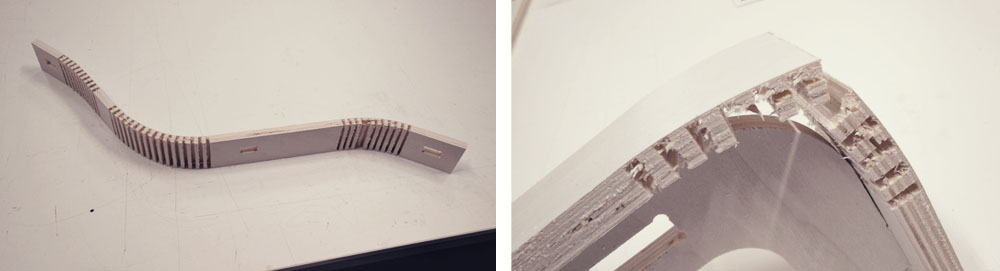
My material was 15mm. so I did a small trial of 14mm. It was too deep and the material broke very easily so I decided to try with 13,5mm. This time the layer of material that was left was strong enough for not breaking but not too thick so It could be bent easily.
It took around 2 hours to cut all the pieces, but only cutting the kerfs for bending took 1 hour of those two. Then, I sanded a bit the edges (I didn't need to sand them too much because the quality of the cut was pretty good) and I assembled all the pieces.
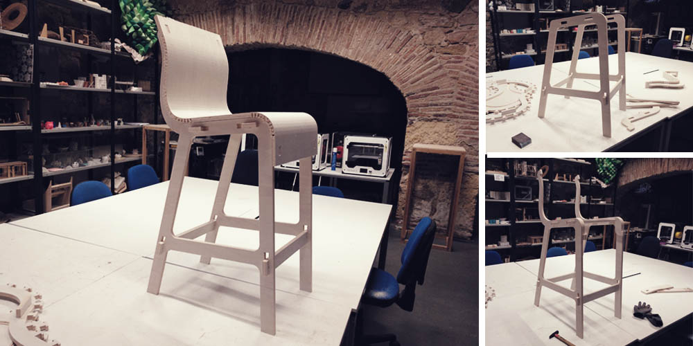
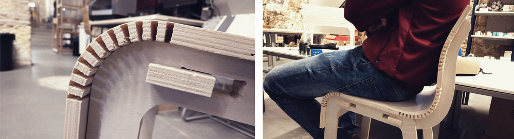
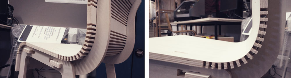
The joints for the kerfing surface worked very well keeping the material over the ribs and adjusting it to the curve. It is a bit unstable because I think that I left too much extra space for the joints of the ribs but it can be solved with a bit of white glue.
Files
Find below the files that I made for this assignment. Please do not hesitate to download it!! I hope you enjoy it!!
Week08_CNC_chair+stool - .pdf