Embedded programming
Week 09
Like every week I started the week planning the assignment. I ordered a Raspberry Pi and a micro:bit boards for the group assignment so this week I had to wait until Tuesday to fill that part of the assignment.
Group assignment. Comparing the performance and development workflows for other architectures
I usually do the group assignments individually as I am a remote student and none of my colleagues are in the fab academy, but in this case, we decided to meet the four of us (Leon remote students) and do some group assignments together.
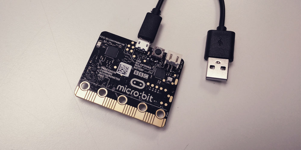
For this part of the assigment, we finally decided to try with a micro:bit board in order to compare the performance and development workflows for other architectures. You can program a micro:bit using blocks, JavaScript and Python. The board has a lot of different features already integrated, such us 25 individually-programmable LEDs; 2 programmable buttons; light and temperature sensors; motion sensors (accelerometer and compass) or wireless communication via Radio and Bluetooth. It works with 3V and 5mA and used a 16 MHz 32-bit ARM Cortex-M0 microcontroller.
We decided to use the MakeCode Editor to program the micro:bit board using blocks and JavaScript. With this app, you only have to go adding the components and functions that you want to use. These blocks have different shapes so only the ones who can work together fit each other). You also have a preview in where you can try what your code will do before uploading it to the board. When your code is ready you only have to download it and the app gives you a .hex file. You just have to save it in the board and that's it!
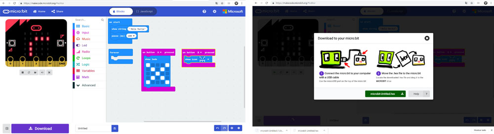
We started playing with simple programs using the buttons and the LEDs and then we tried with the accelerometer. Please, find here the .hex file.
This kind of boards are awesome if you want to start with the electronics but you don't know to code or you don't have the facilities to fabricate your own PCBs.
Reading the datasheet for ATtiny44A microcontroller
Before starting to program the board is recommended to have some knowledge about the components and microcontroller you are using and the specifications that it has. So to do that I read the datasheet of ATtiny44A extracting the most important concepts and information of it.
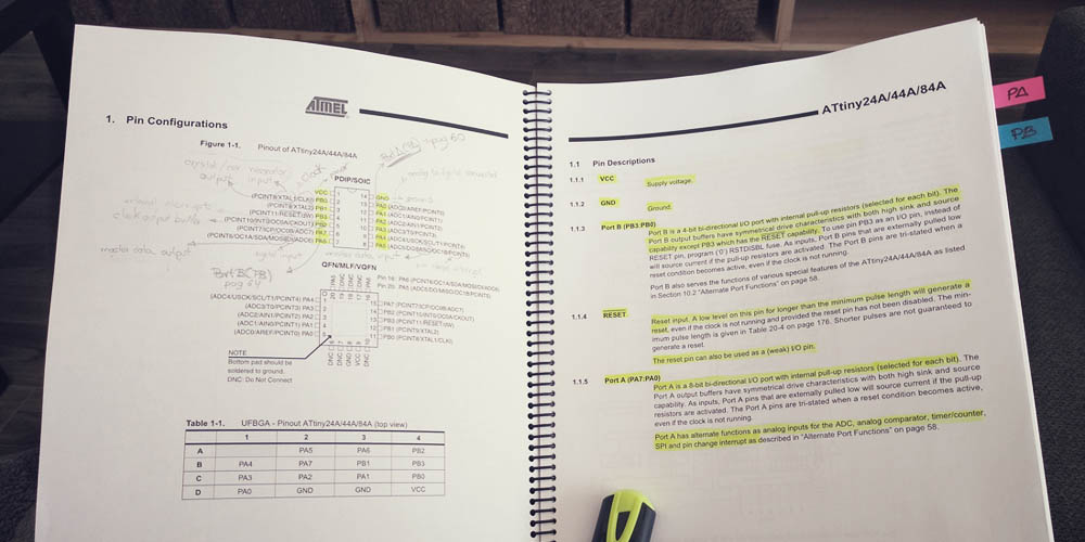
I think that one of the most important things is to know what pins you have in your microcontroller and so to know where you have to connect the components so they can work properly:
> GND: ground.
> VCC: supply voltage.
> Port A (0-7): Port A is a 8-bit bi-directional I/O port with internal pull-up resistors.
> Port B (0-3): Port B is a 4-bit bi-directional I/O port with internal pull-up resistors.
> RESET: Reset input.
> MISO: Master Data input (the data comes into the microcontroller through this pin).
> MOSI: Master Data output (the data comes out to the microcontroller through this pin).
All the pins, except for the GND and VCC, can be used as both input and output, but some of them have alternative functions, for example, when you want to connect the SPI some of them need to have a specific function: you need to use the PA5 as a MISO and the PA6 as a MOSI, but the rest of the time they can be used for other things.
Another important thing that the datasheet is telling us is that you have to keep in mind which kind of input component you are using, digital or analog: for instance, if you are using a temperature sensor (analog component) you have to connect it to an ACD (analog to digital converter) port otherwise the microcontroller isn't able to transform the information that is receiving from the sensor to a digital data.
I was new to this topic, so it was difficult to read the datasheet due to the technical vocabulary. Being honest, if you have no experience (which was my case) it is a nightmare. I started with a lot of encouragement with my fluorescent marker in hand since I was very interested in knowing what happens inside of that little universe that is an ATtiny. However, I couldn't read more than a few pages, maybe 20 as much. The datasheet is not a book, is a manual. It is full of technical concepts and references which are impossible to understand for a beginner.
So I decided to look for the more interesting and useful information that I thought it would we the reference of each pin, you know, which are de functions that each pin can support, and that helped me to understand the design of the Hello board, for instance.
Programming with Arduino IDE
The first thing that I did was to download Arduino IDE, v.1.6.5. Then I loaded the Board Manager ATTinyCore by Spencer Konde. To do that, in Arduino IDE, I went to file > preferences and in section Additional Boards Manager URLs I copied this URL: http://drazzy.com/package_drazzy.com_index.json. Once this was done I went to tools > board > board manager. In the browser I typed "attiny", I looked for the ATTinyCore by Spencer Konde library and I installed.
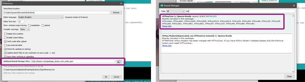
To apply all the changes and new information I closed Arduino IDE and I opened it again. Then, from the tools tab, I chose the version of my PCB board, chip, and clock, as well as the type of programmer.
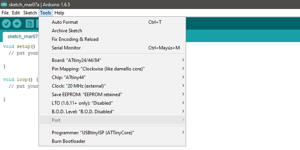
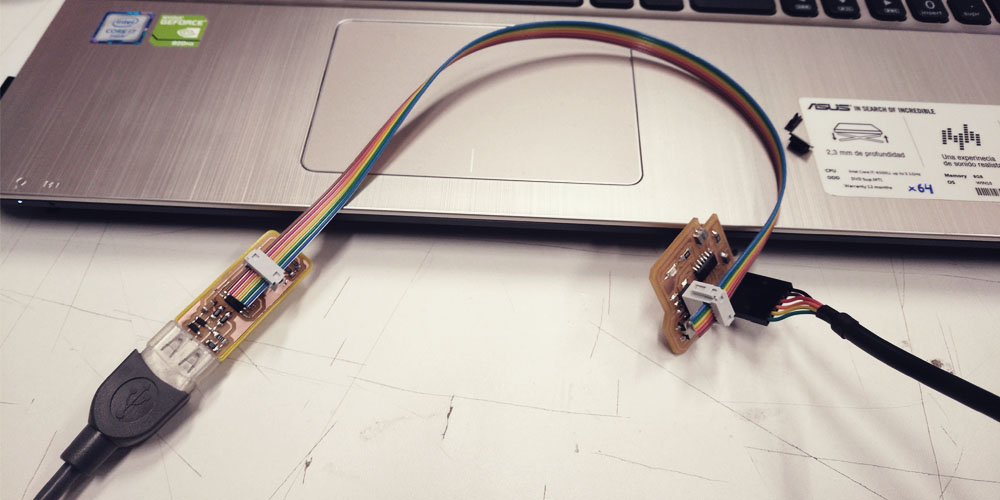
The next step would be to connect the FabISP and the Hello BOARD each other (with the cords in the correct way, keepeng in mind where the ground is) and to the computer and run the burn bootloader command from the tools bar. It worked.
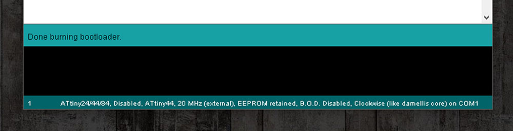
You have to run this command each time that you want to load a new programme. What the "burn bootloader" does is to reset the memory of the microcontroller.
To know where is the ground in my FTDI cord I used this image: Cable ftdi pinout
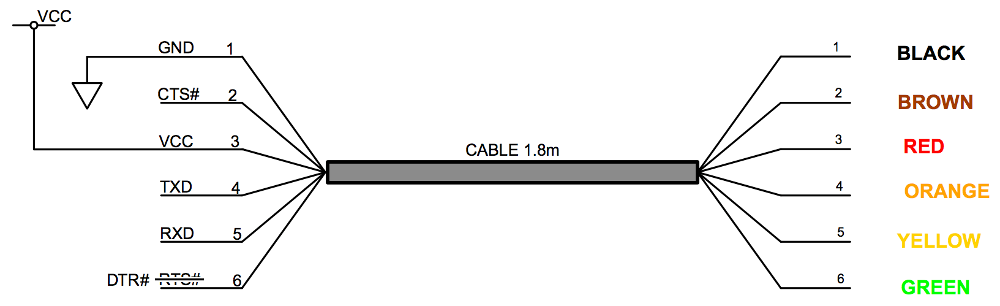
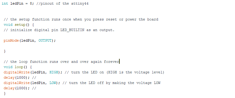
I hadn't worked with Arduino before so one of my colleagues gives me a basic explanation of how the code works and after following some tutorials, such as the ones that I found in the Youtube channel Tech Krowd, I was ready to send my first programme, a loop that turns on and off the led each 1 second.
To know for Arduino in which pin is the led and button in my Hello Board I used this image: ATtiny 24/44/84 pinout
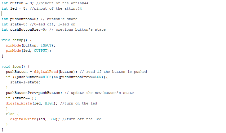
Then I made a second programme which turns the LED on while you keep pushing the button.

In this third programme I wanted to use the button as a switch that turns the LED on and off when you push it.
And finally for this fourth programme I wanted to try to change the intensity of the light taking advantage of the fact that my LED was located in an analog input.
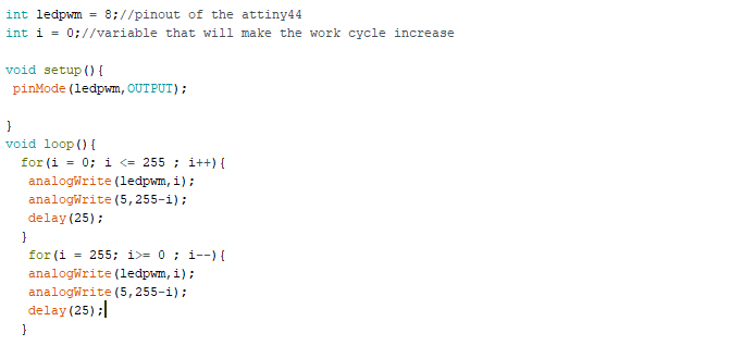
I would have liked to do a fifth programme joining the third and the fourth ones, but this is addictive! I could be all day creating new programmes, and just playing with a LED and button! But I decided to stop, as this was taking more time than I expected and I needed to continue with the assignment.
Programming with C
After this successful uploads through Arduino IDE, I decided to test a blinky led coded in C using makeFiles. I looked for other years examples (I had zero experience with C, so I thought it would be a nightmare to try to code from scratch) and I found Marta Verde's assignment. She has an example using a LED and a button, and I thought that's would be perfect for me to start understanding the syntax and the code, and I made my own version modifying little things.
First of all I downloaded and instaled Notepad++ in order to be able to motify the .c and .c.make files.
Then I changed the name of the project on the .c.make file according to the name of my .c file and then I changed de pins' numbers according to the connexions that I did between the LED, the button and the ATtiny.
Once this was done:
1.- I opened GitBash and I navigated to the folder where my files were using the cd command.
2.- I typed and run the command make -f helloLED.c.make (This should check the code for errors before compiling and list them out in the terminal if any exist. It should then create a hex file.) It worked.
3.- I typed and run the command sudo make -f helloLED.c.make program-usbtiny-fuses (This should prepare the chip to write). But... It didn't work: command not found. I didn't know why but my instructor told me that some times the sudo gives problems. So I typed and run make -f helloLED.c.make program-usbtiny-fuses and this time it worked.
4.- I typed and run the command make -f helloLED.c.make program-usbtiny. (This writes the program to the chip). It worked too, no errors, but my board didn't work. I pushed the button several times but the LED didn't light. So I went to the code and I checked it. I changed the code two times until It worked. I made two mistakes: first I used the Arduino number for the pin's number and second, I forgot to change the name of the port to PORTB, as my LED was in the PB2.
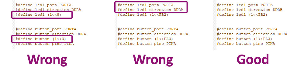
When the pin's and port's names were correct, I was able to program the board and the LED flashed when I pushed the button. In the image bellow you can see the whole process and here you can find the HelloLED.c file and the HelloLED.c.make file.

I think the best part of programming this kind of boards is when the magic happens, you know, when the code that you wrote produce that your LED shines. It is very satisfying, even if you are doing the most basic thing. When it works it makes you very excited.
Extra: saving time
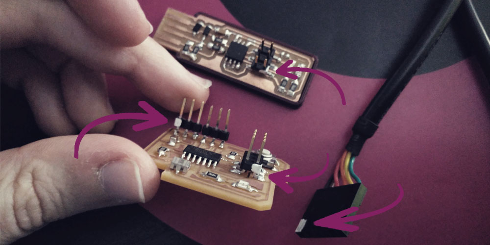
I was wasting so much time finding the GND of my components each time that I wanted to program the board that at some point of the week I decided to make small white marks so it would be very easy to connect them in the correct way. It is a very simple thing that saved (and will save) me a lot of time.
Files
Find below the files that I made for this assignment. Please do not hesitate to download it!! I hope you enjoy it!!
Arduino IDE - programme 01 - .ino
Arduino IDE - programme 02 - .ino
Arduino IDE - programme 03 - .ino
Arduino IDE - programme 04 - .ino
HelloLED.c file
HelloLED.c.make file