Week assignments
Group assignment
- Characterize the design rules for your PCB production process
Individual assignments
- Make an in-circuit programmer by milling the PCB
- Program it, then optionally try other PCB processes
PCB production process characterization
You can find documentation about our group assignement on our group page.
Milling the PCB
Step 1: The software part
We used FlatCam to setup the CNC file for the machine. We first had to vectorize the png file into inkscape to be able to open it into flatcam.
We had to specify the cut Z, Travel Z, feed rate, Tool diameter and spindle speed as shown on the picture below.
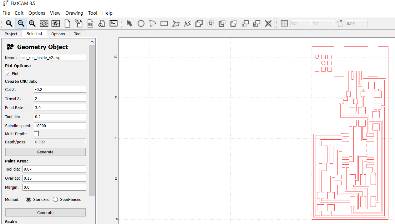
Then by clicking generate, we create a svg_cnc file that we can export as an .nc file readable by the machine.
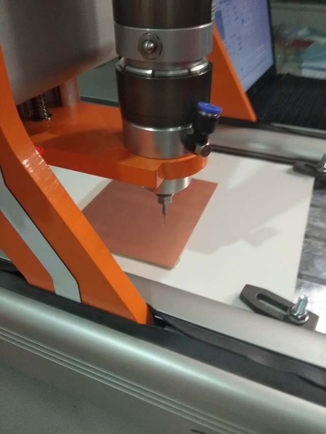
Step 2: The machining part
To mill the PCB, we used a stepcraft 300 that we were able to drive thanks to WinPC-NC.
Most of the parameters have been setup into flatcam. I only had to tick the "invert Z coordinates" option into Import Formats options.
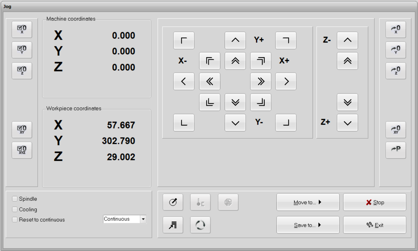
Before launching the machine I had to setup the zero. Into move>jog, we can manually move the machine to our desired zero point. We used a sheet of paper between the mill and the PCB to have a precise Z-zero. When X, Y and Z are to my desired point I just click the 0-XYZ button as shown on the picture below and the machine goes to a safe position 10 millimeters higher.
Then we have to click move>start to launch the job.
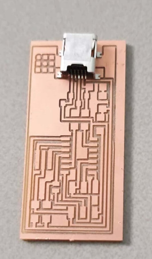
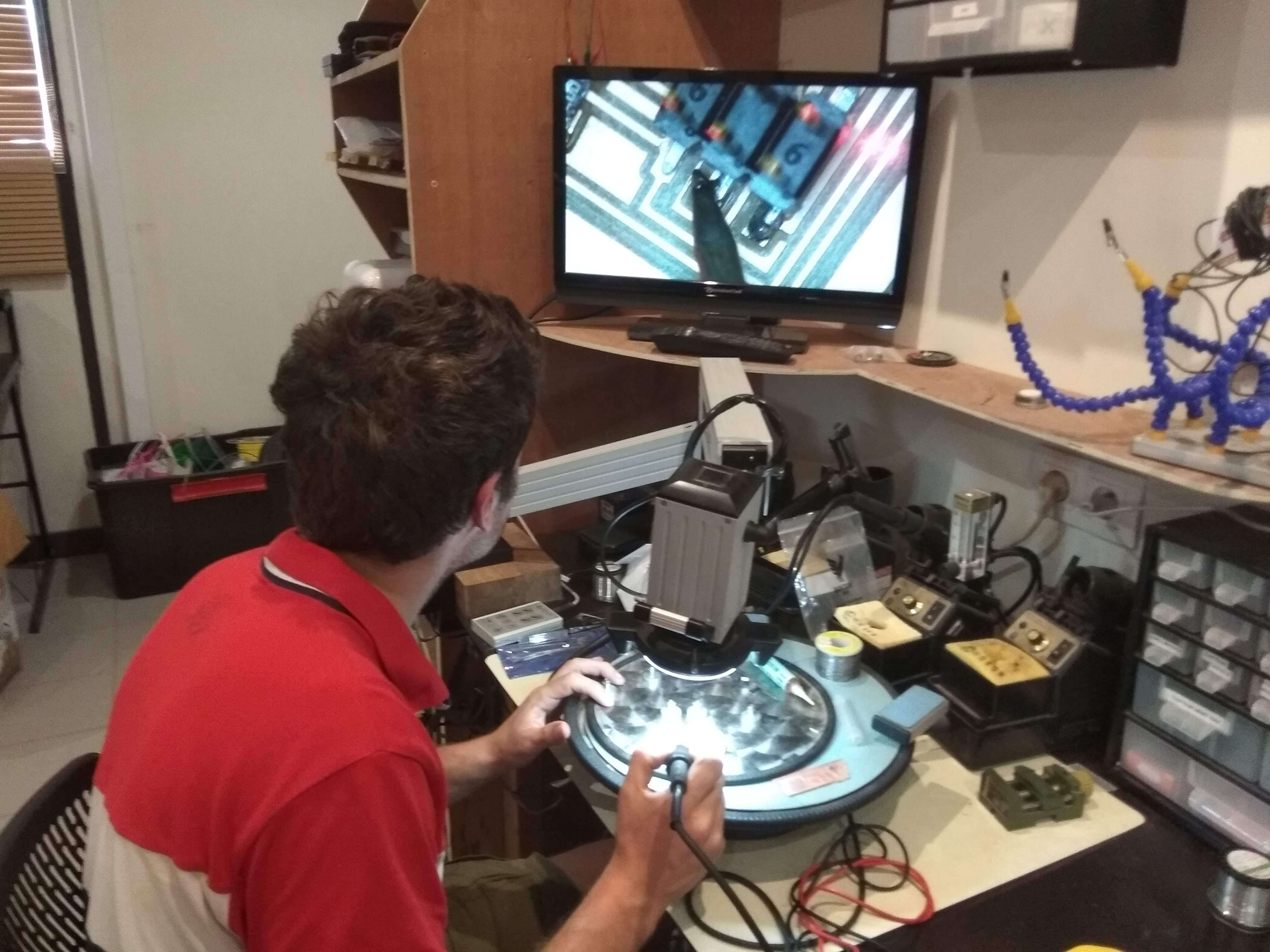
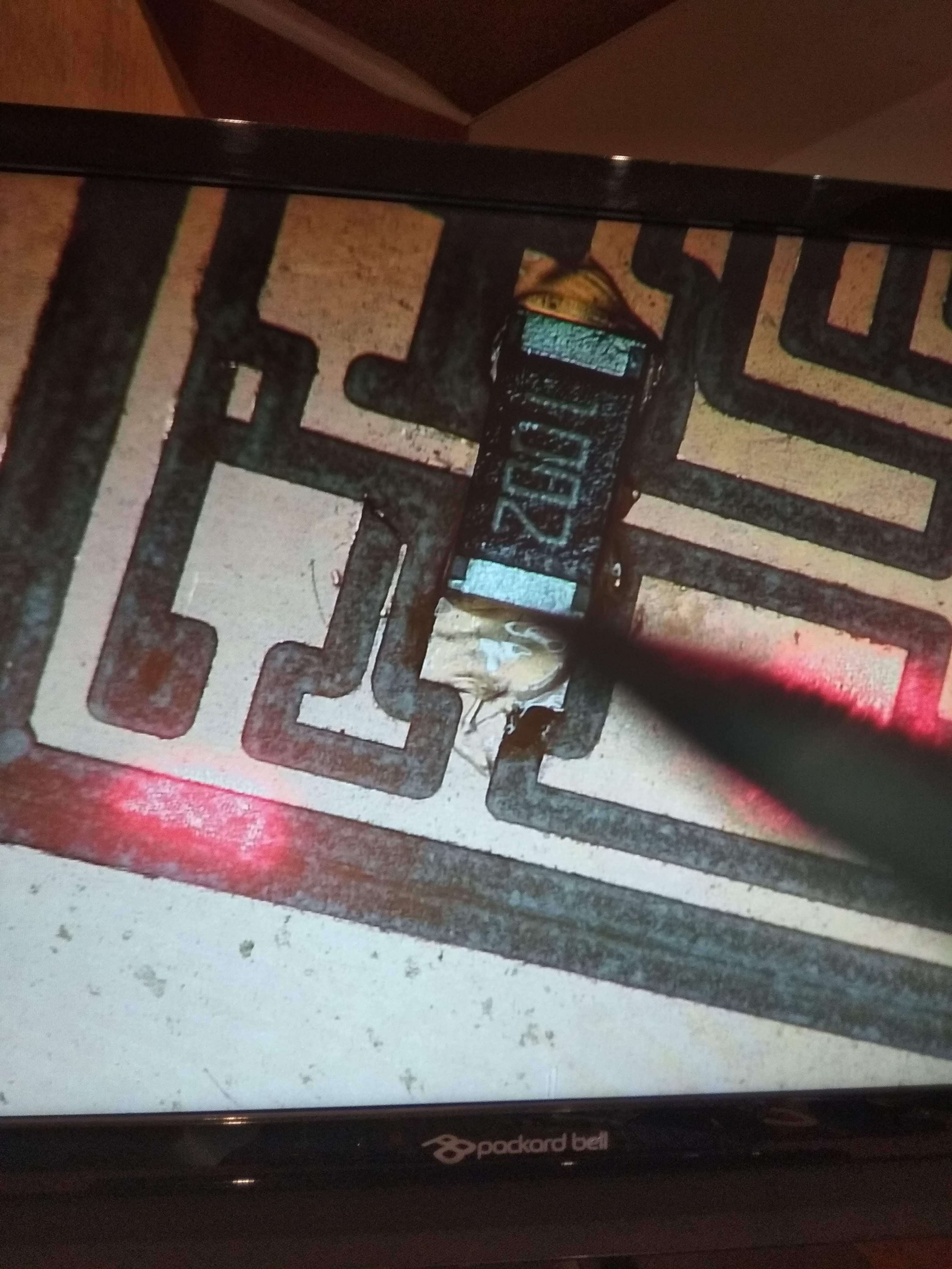
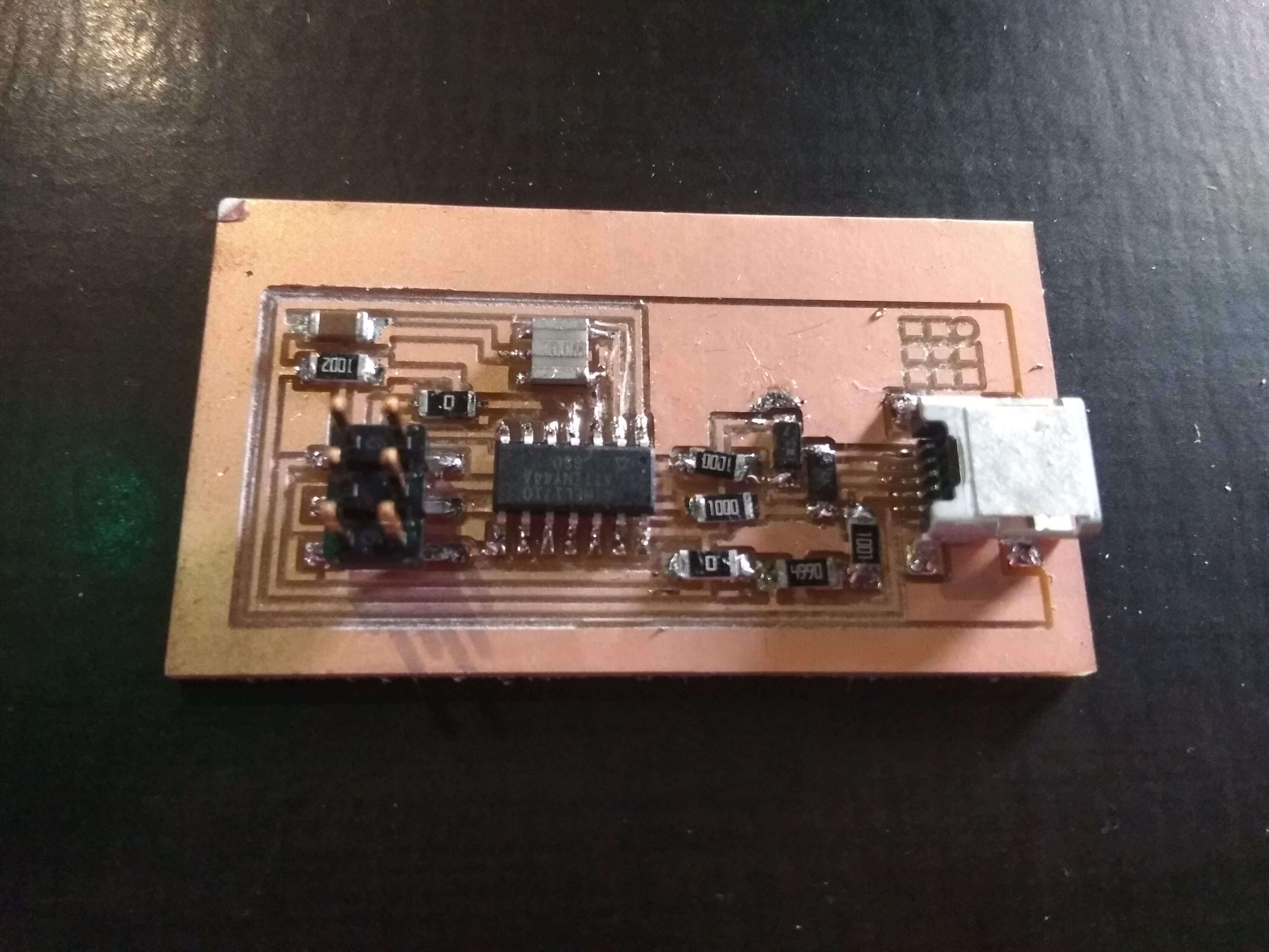
Assembling the PCB
When I first saw the components size I must admit that I wondered how I would be capable to solder them on my PCB. But thanks to my intructors advise and a very good HD cam tool that we have into the fablab I managed to get through it. The pictures are speaking by themselves here.
One important point that reaaly changed the quality of my soldering was the application of the good amount of fluxes.
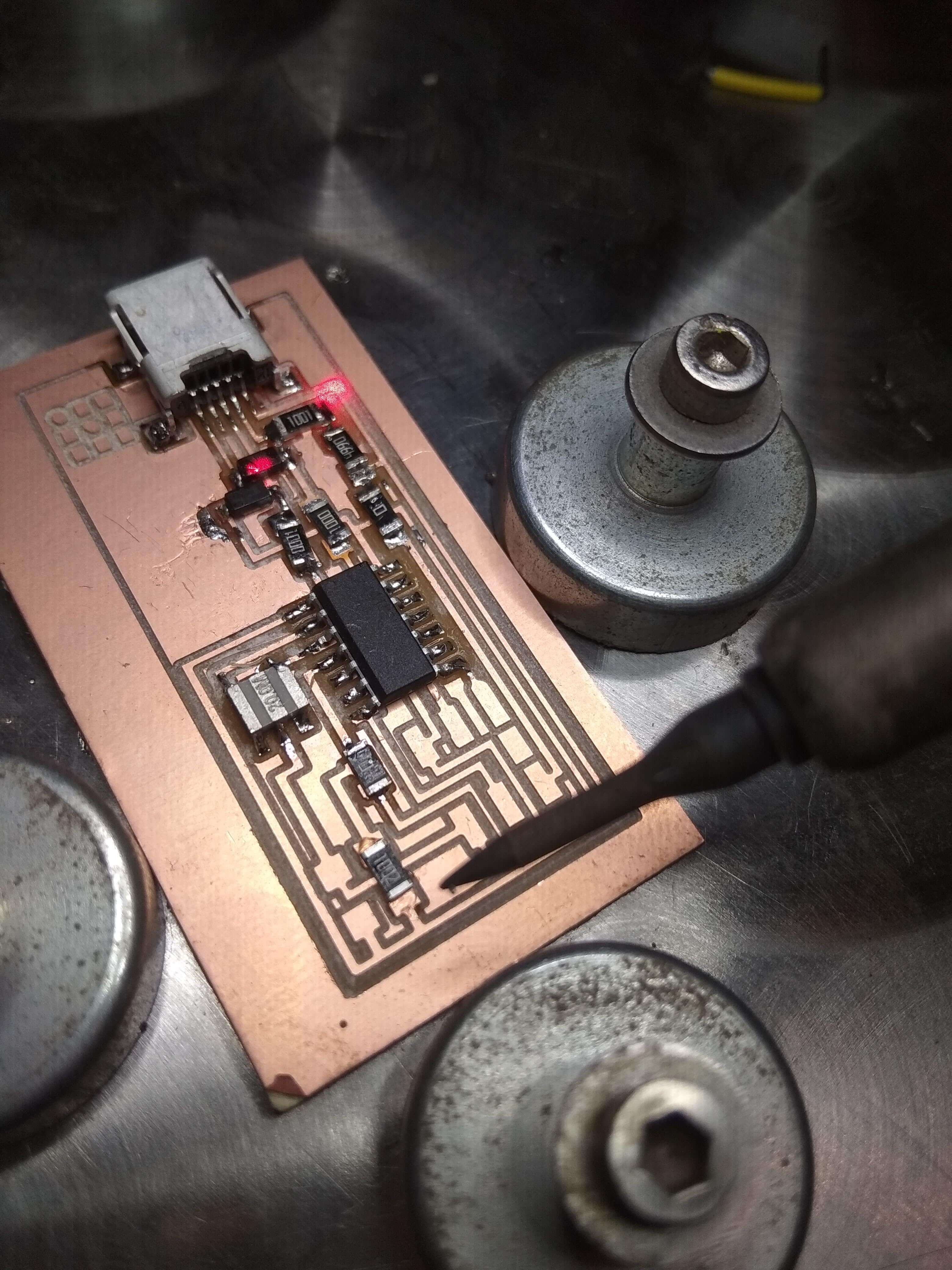
Flashing the firmware
I used Arduino as ISP to flash my FabISP.
First I had to upload the "Arduino as ISP" program to the arduino through the arduino IDE.
The next step was to follow the fabacademy tutorial
After having installed the necessary softwares for AVR programming on Ubuntu, I used the following commands:
make clean #to compile the firmware
make hex
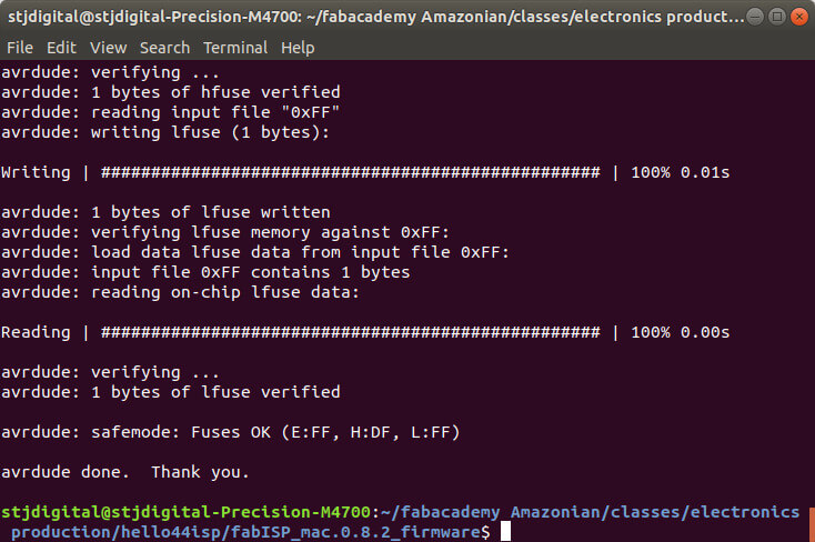
make fuse #setting the fuse to use the external clock
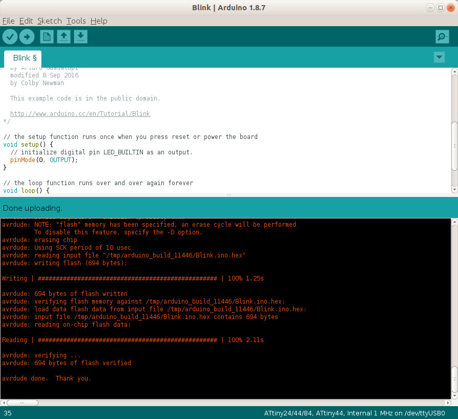
make program #Programing the board to be an ISPHere is the result of the flashing:
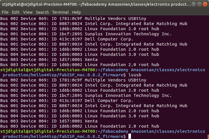
Then by taping lsub command I was able to see "Multiple Vendors USBtiny" in the device list:
I used the following parameters in ArduinoIDE to burn the bootloader of another board
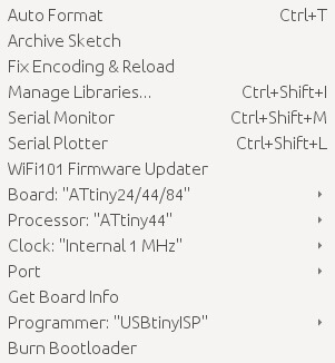
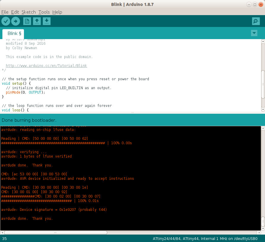
And eventually, I was able to program the other board: