
Make something Big on a CNC Machine
.
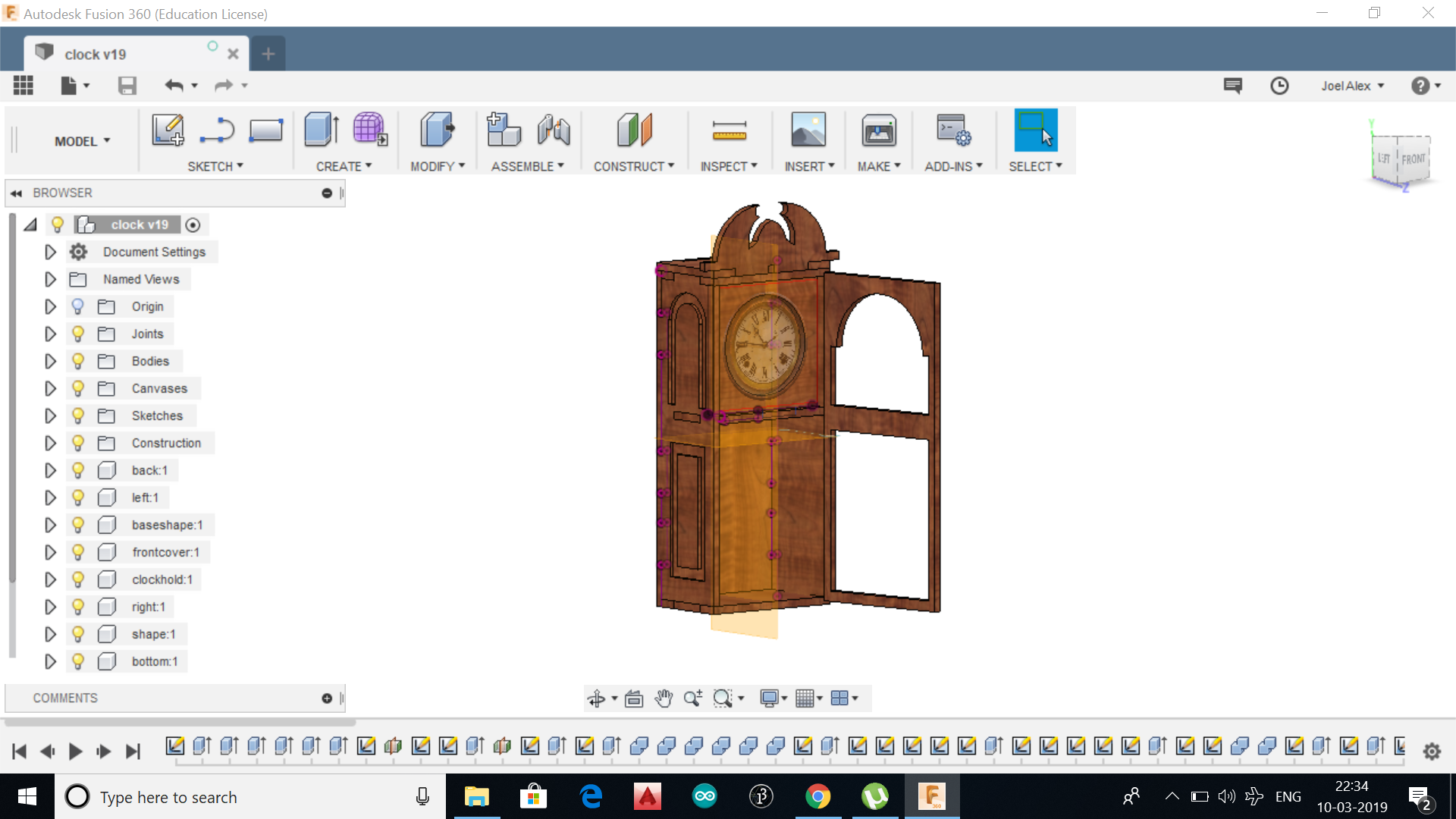
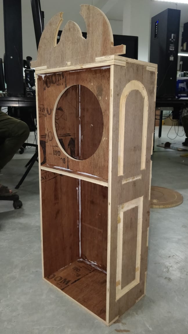
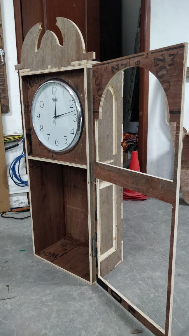
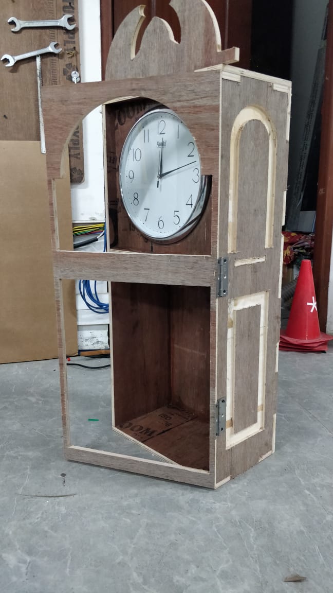
This week i thought i would make something other than furnitures, as i am seeing so many furnitures in the lab. I was fascinated by an old pendulum clock in my home which is currently not working. So i thought i would replicate the desig of the same.
.
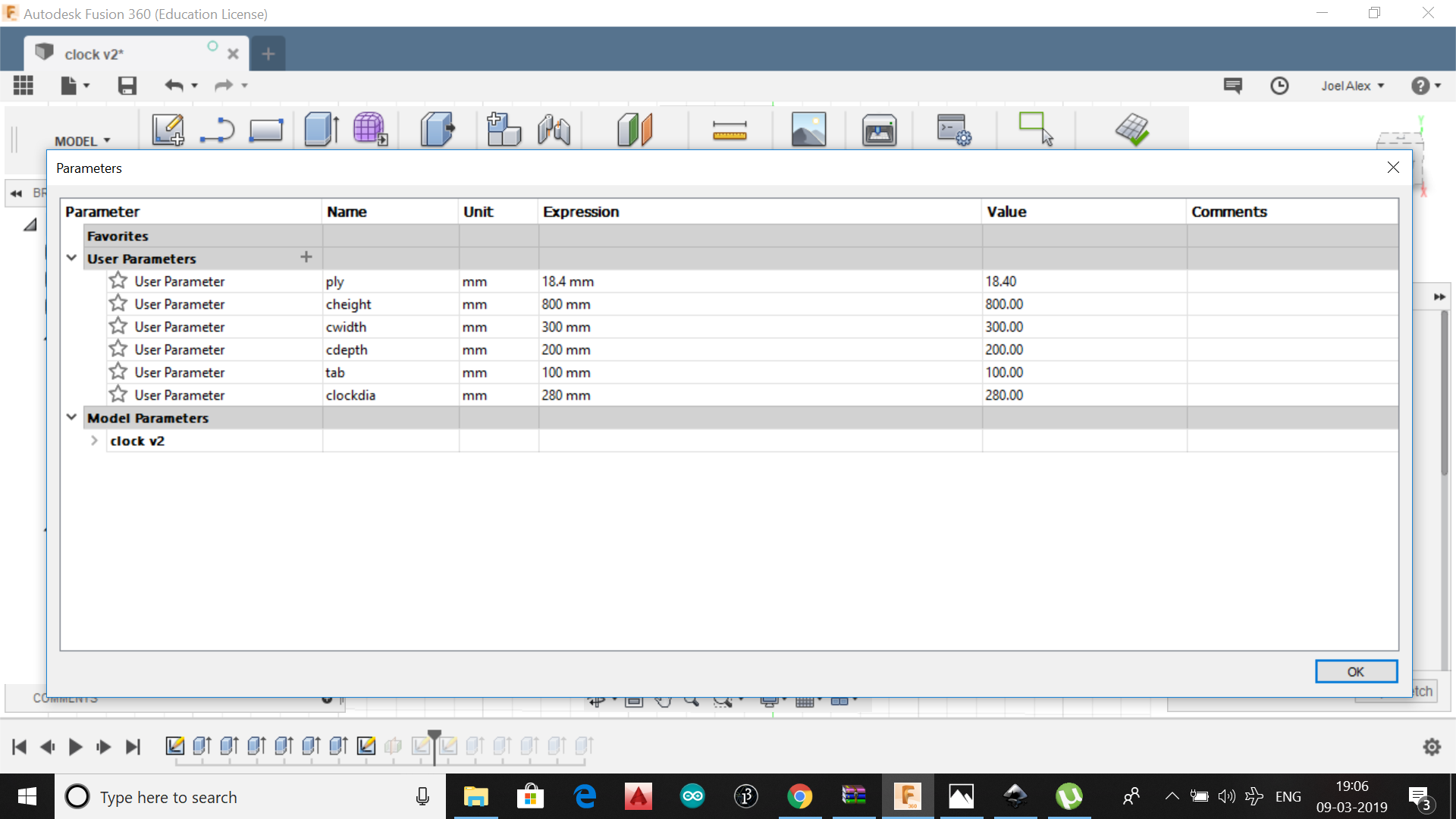
Since i became addicted to fusion 360, i chose the same for designing
.
.
Since the pendulum clock was based on pressfit, i thought it would be easy to design the 3d object and then to align the sketch in plywood for cutting
.
.
.
.
.
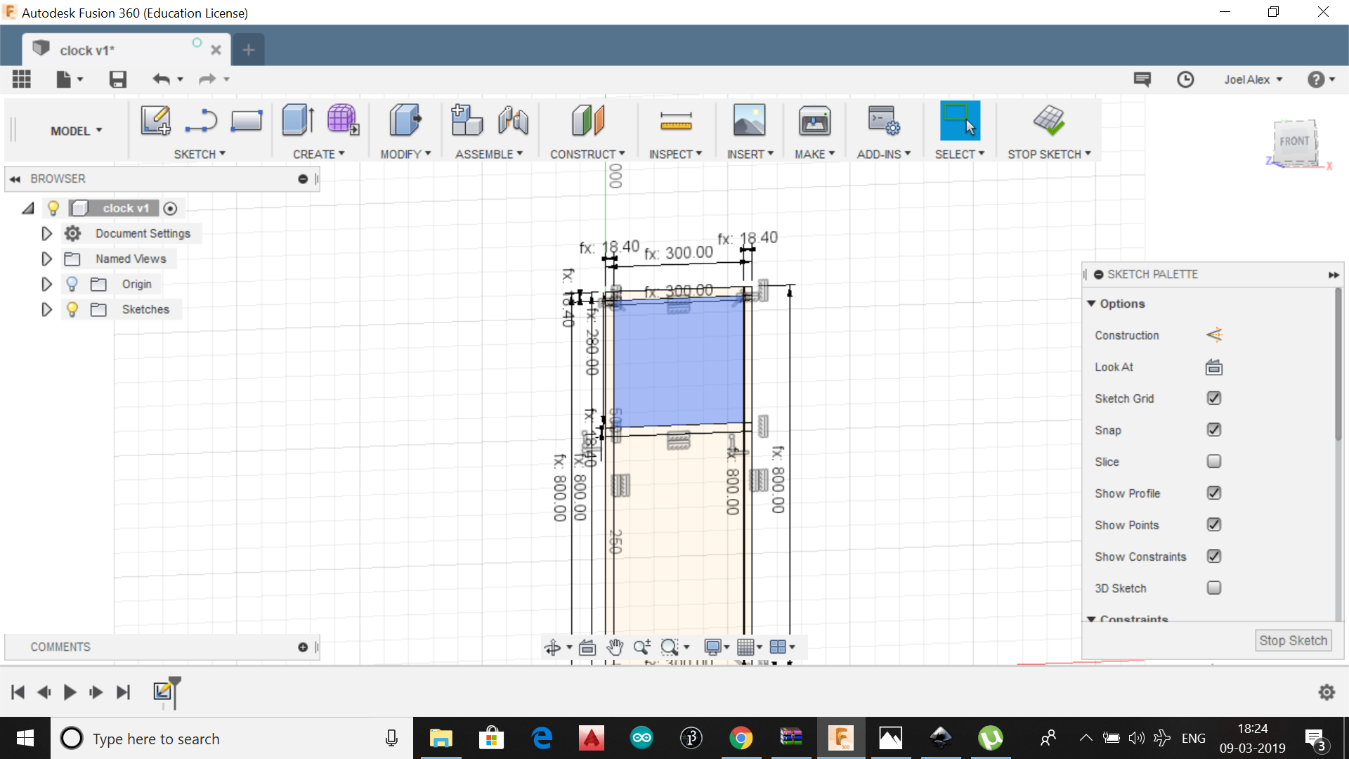
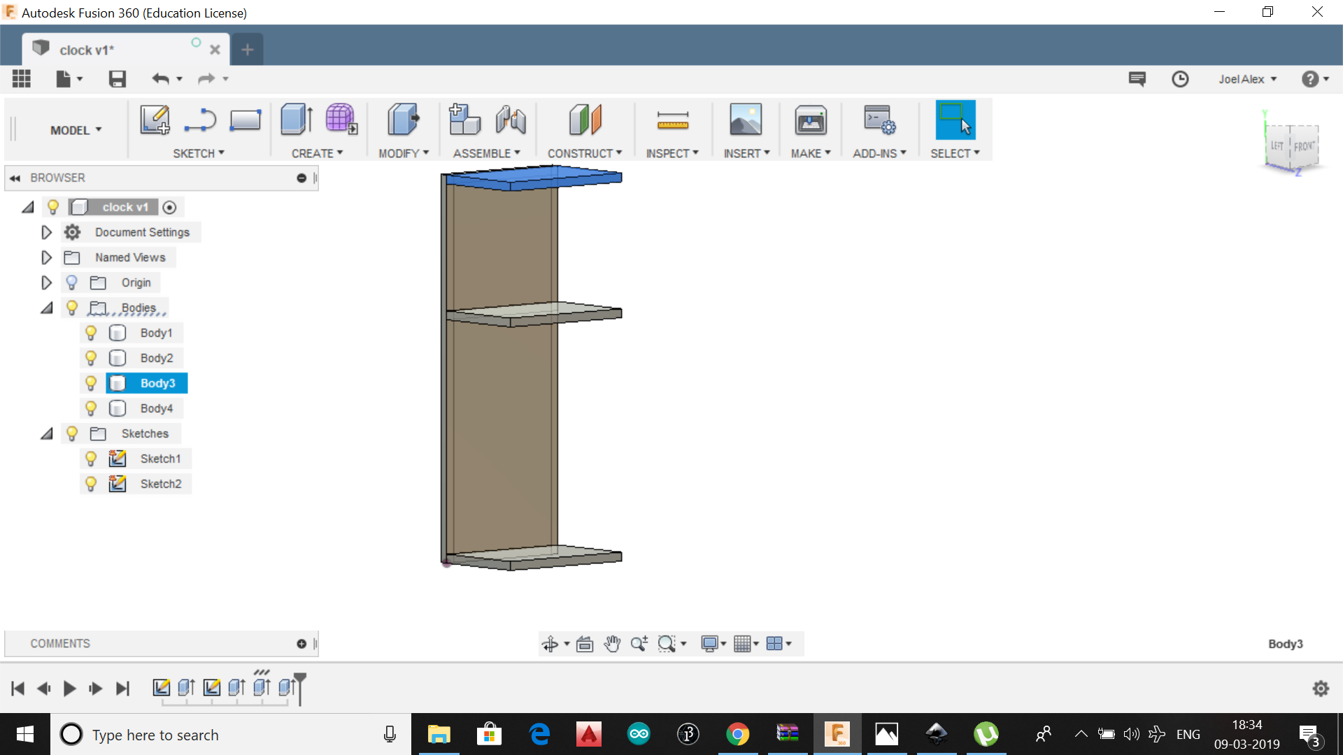
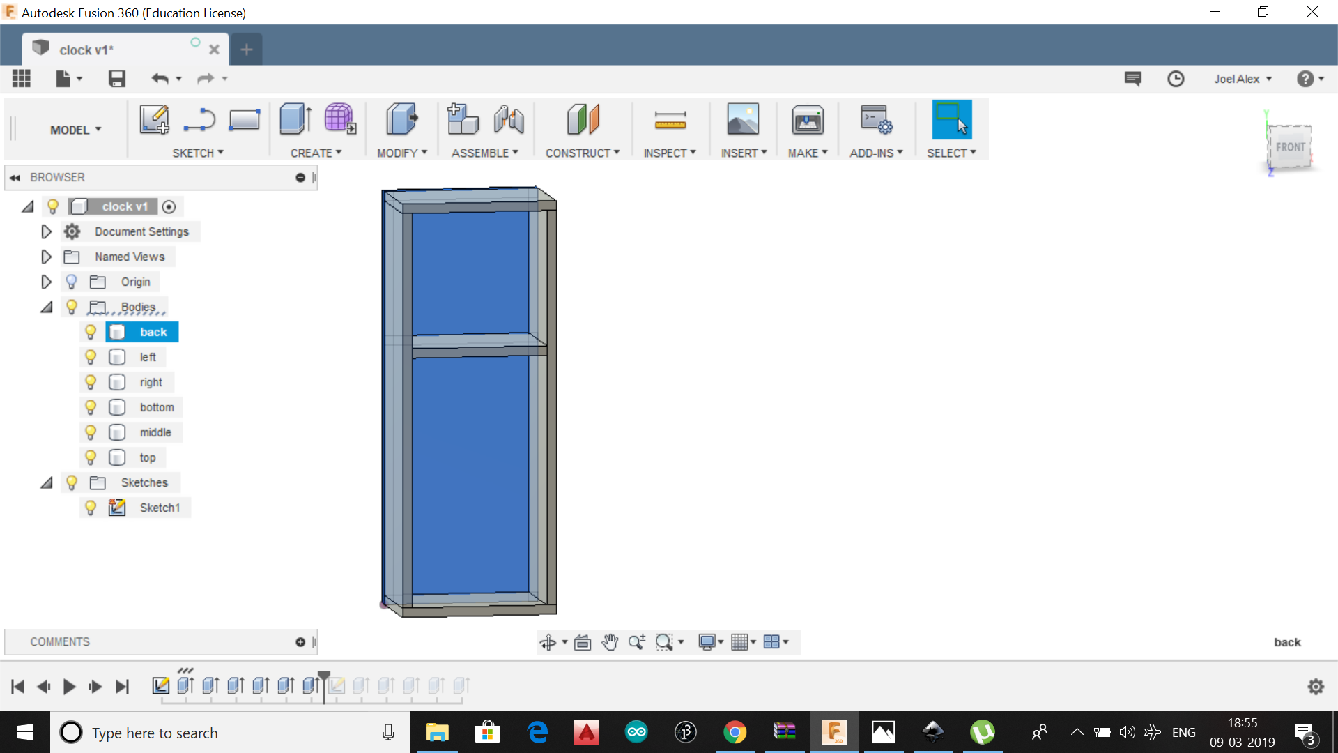
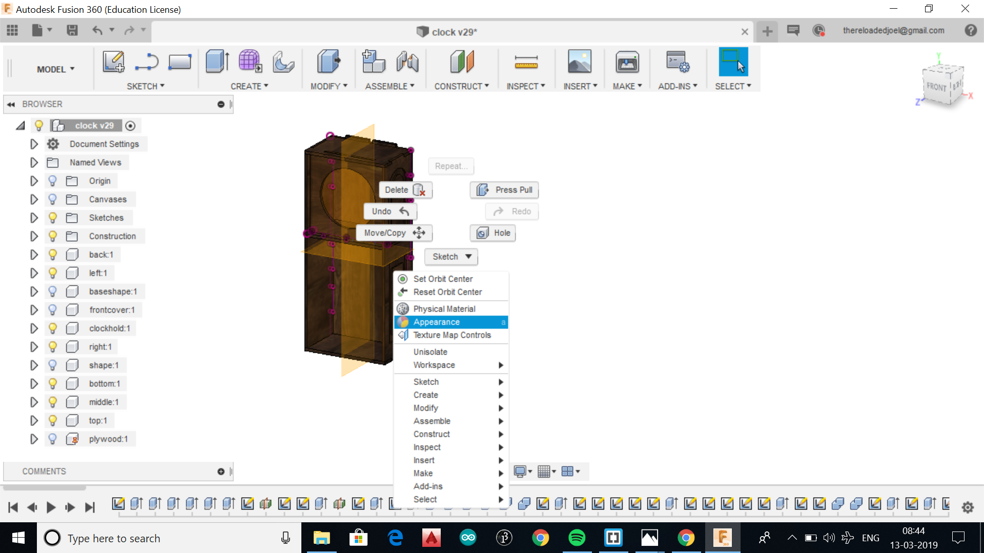
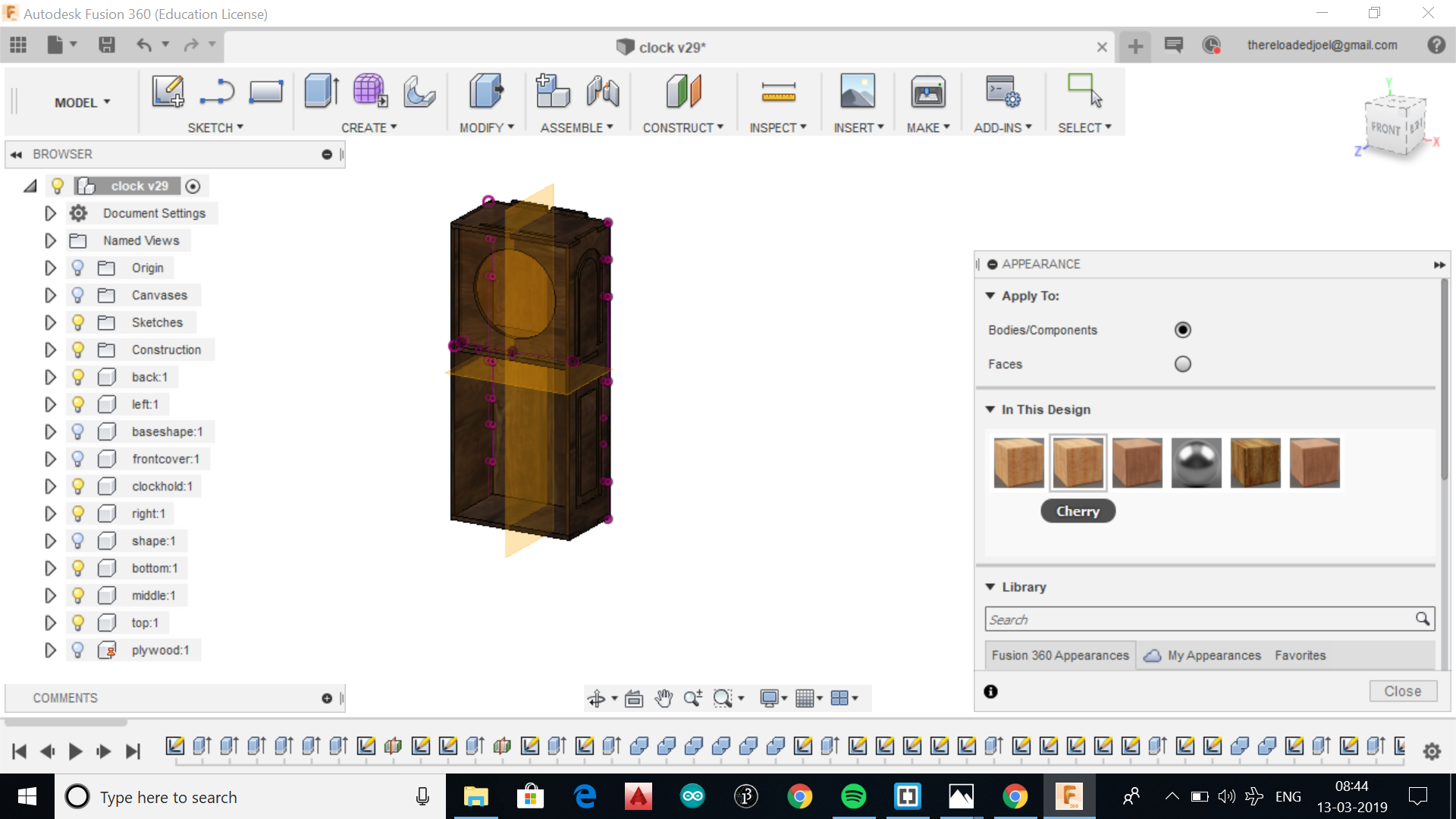
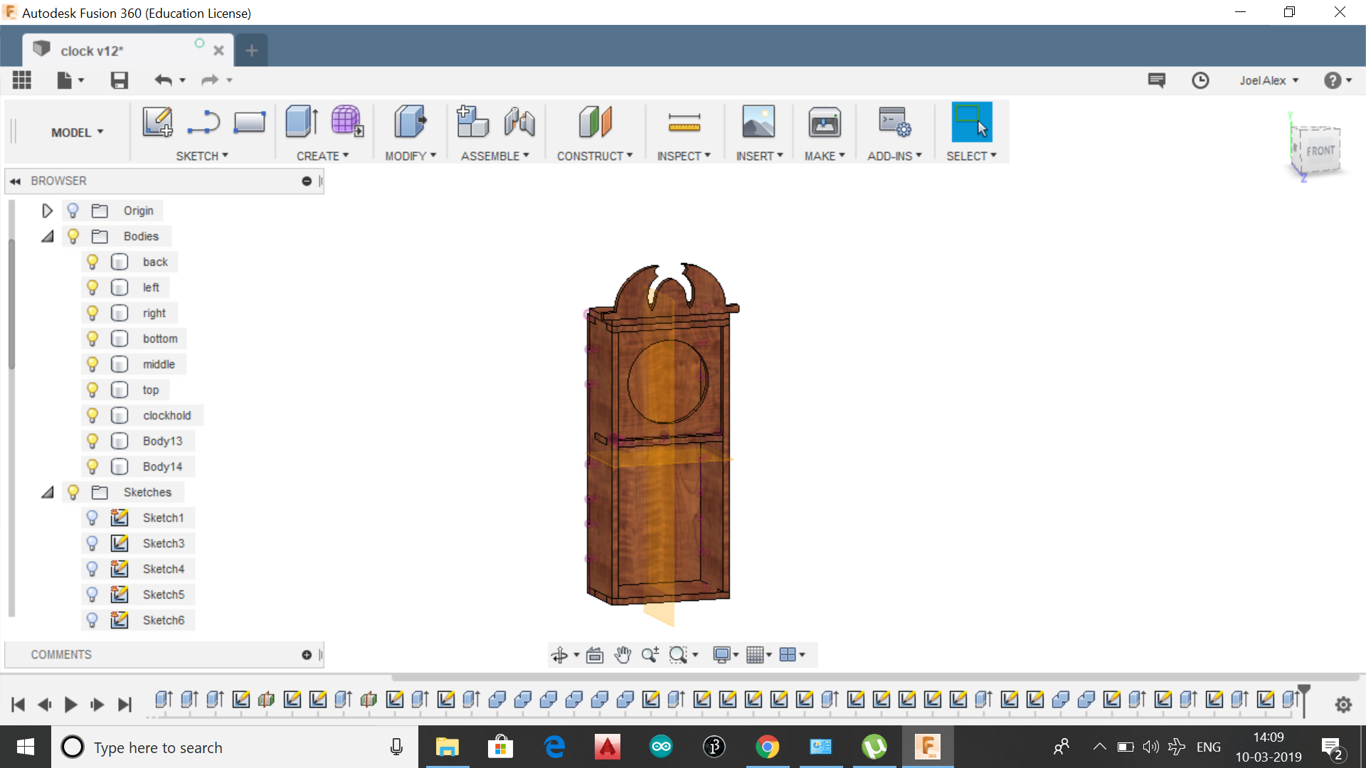
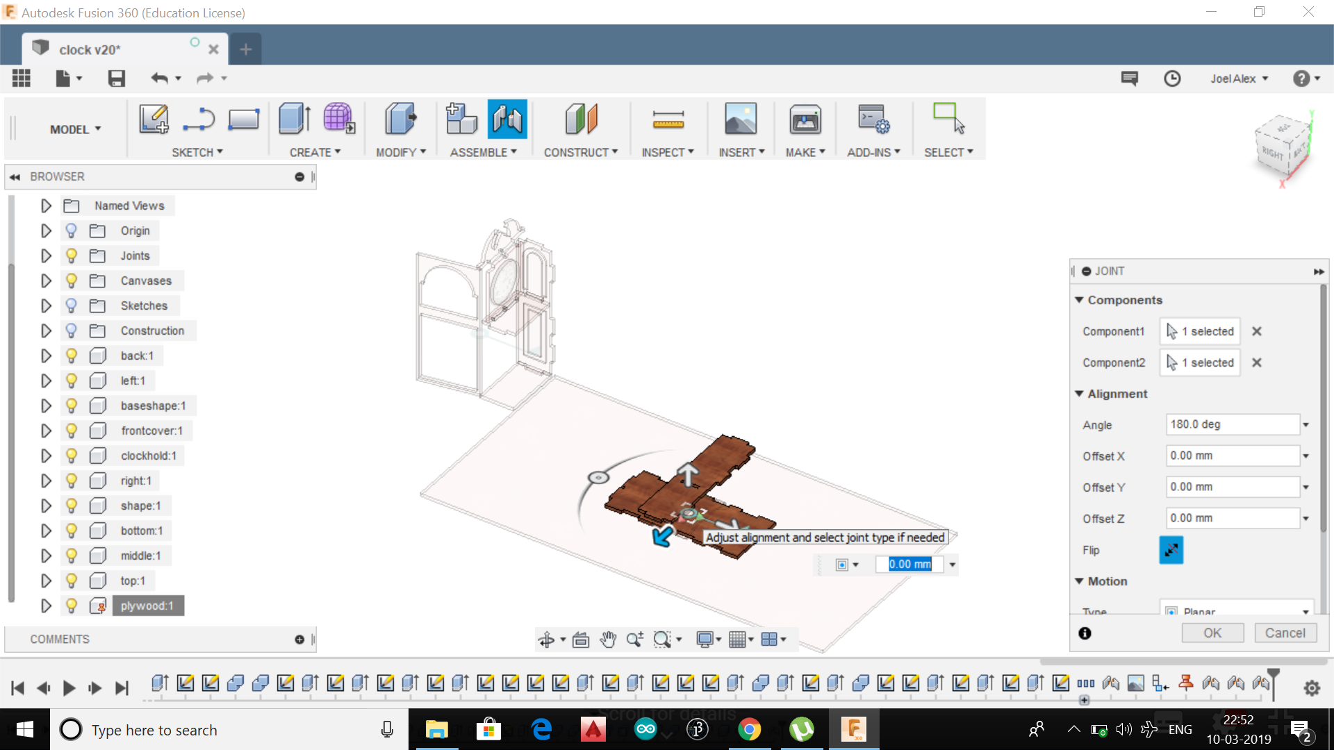
As we are going to transform the 3D to 2D, we need to make every sides of the clock as seperate bodies, by selecting 'new body' after extruding a sketch.
.
.
.
.
.
.
.
.
.
.
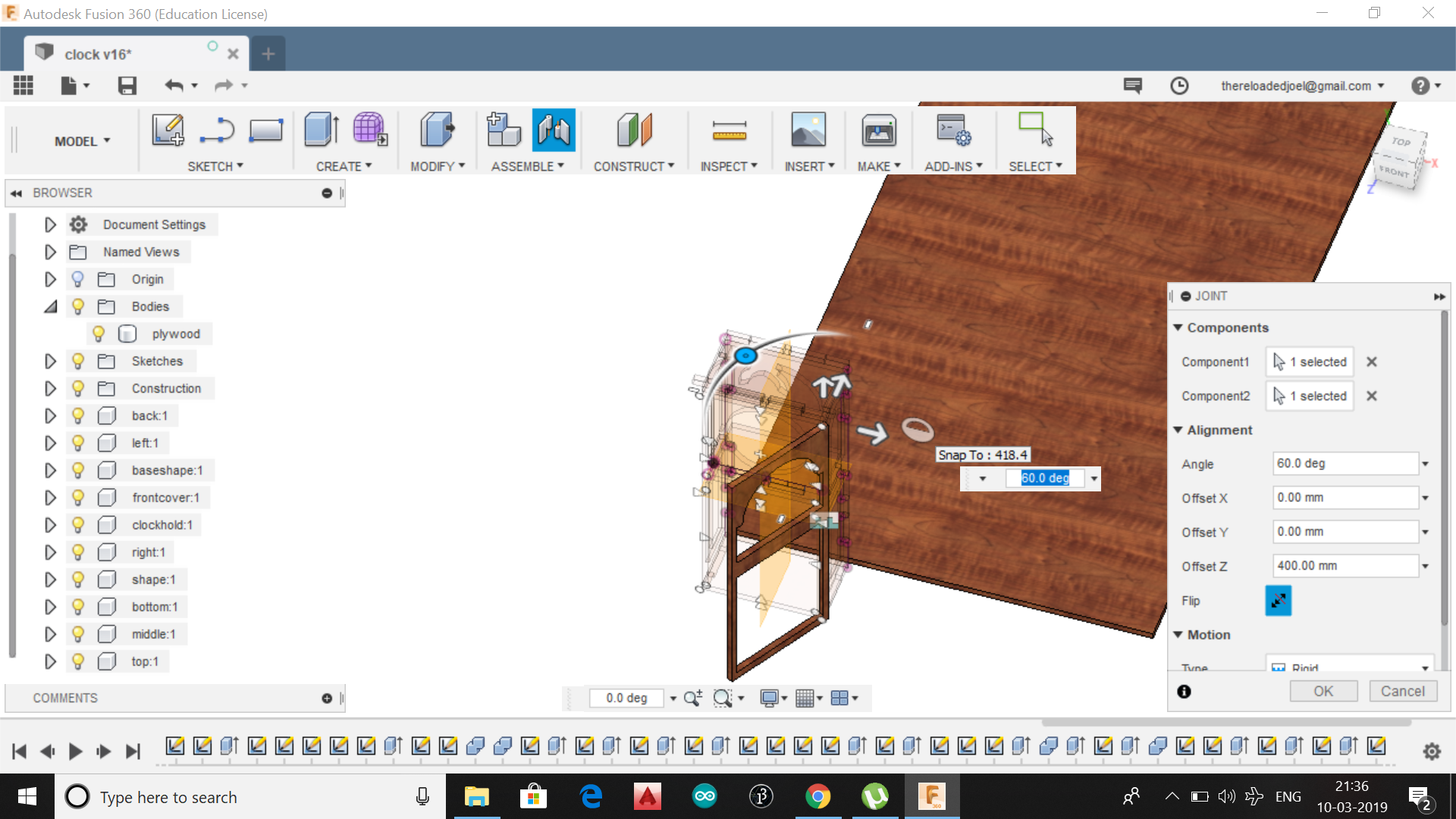
Inorder to have pressfit joint, draw 'tabs' at required intervals on all the sides. Tab is the length of the pressfit joint (usually length of side/3) and width should be equal to the size of plywood, since we need to fit the joints correctly. After creating tabs on every body as required, the tabs should be extruded as below and the body should be joined as a single body with the side .
.
.
.
.
.
.
.
.
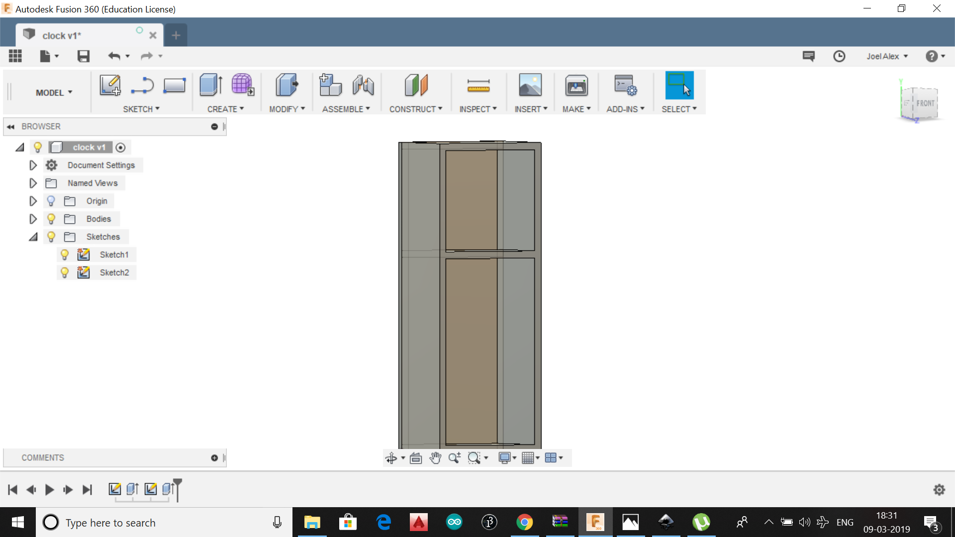
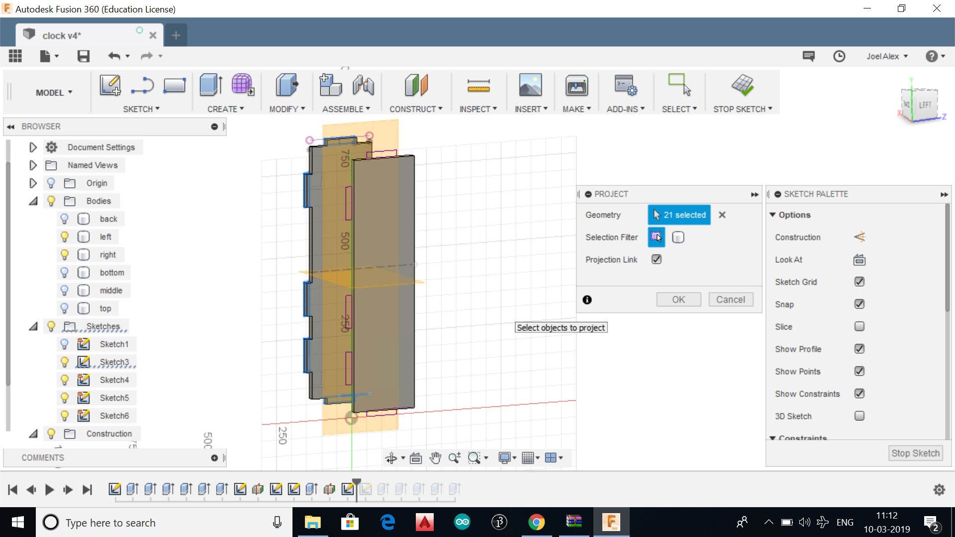
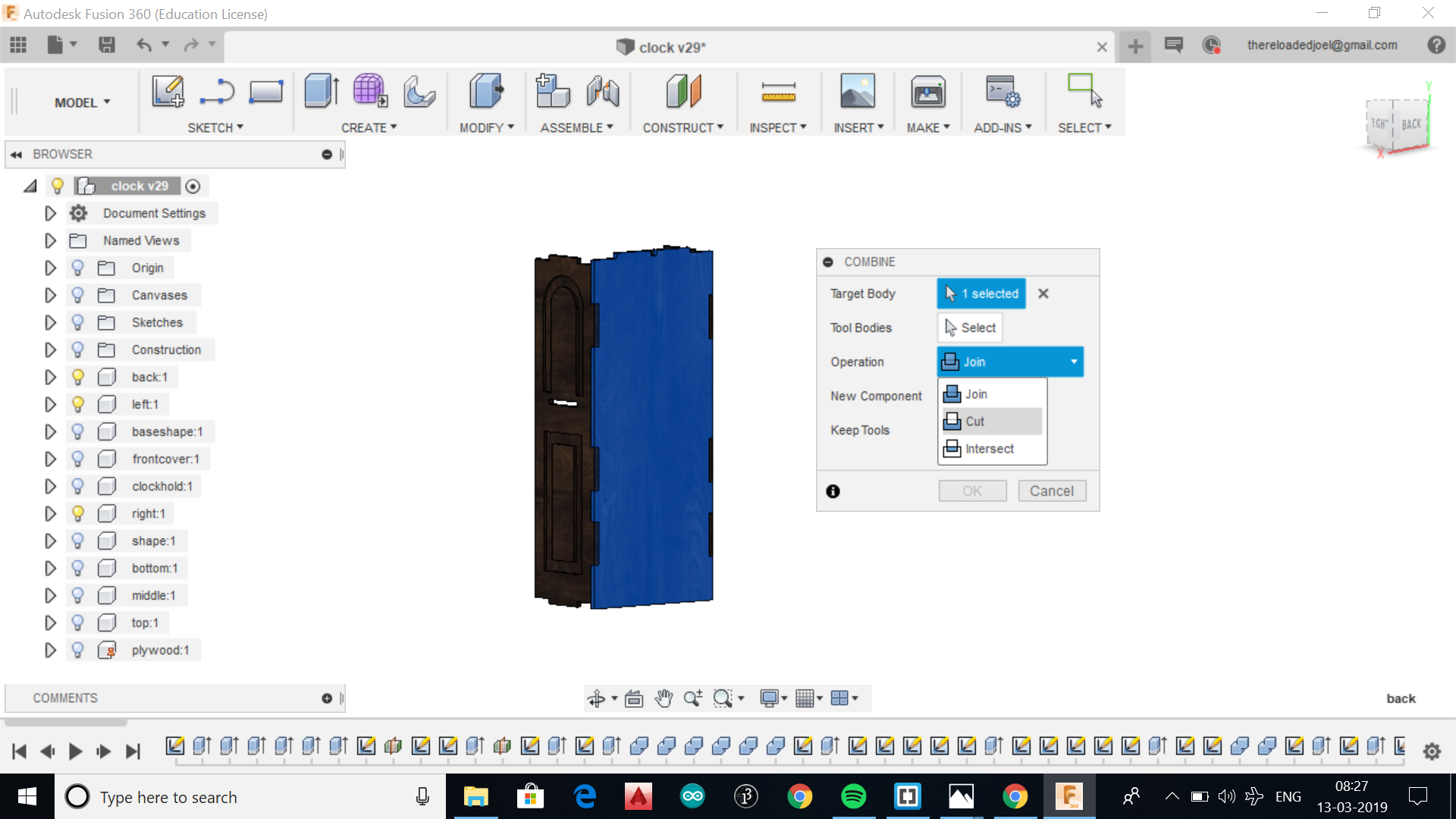
Now the bodies will be having required pressfit joints. But as they are seperate and needs to be combined to get correct pressfit joints we need to combine them seperately and deduct the unused area.
.
.
.
.
.
.
.
.
.
.
.
.
.
.
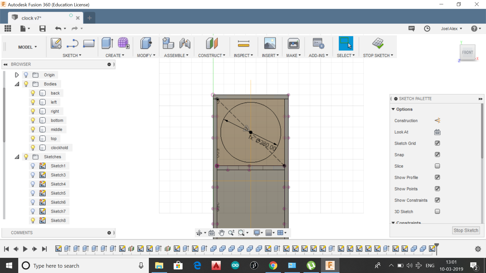
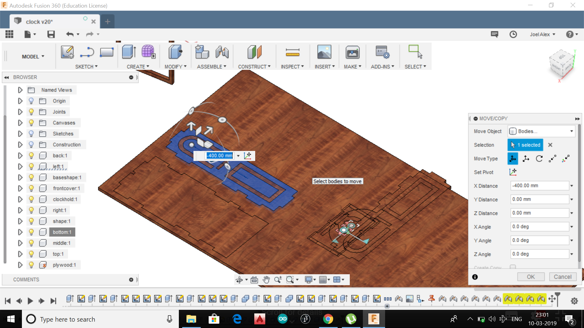
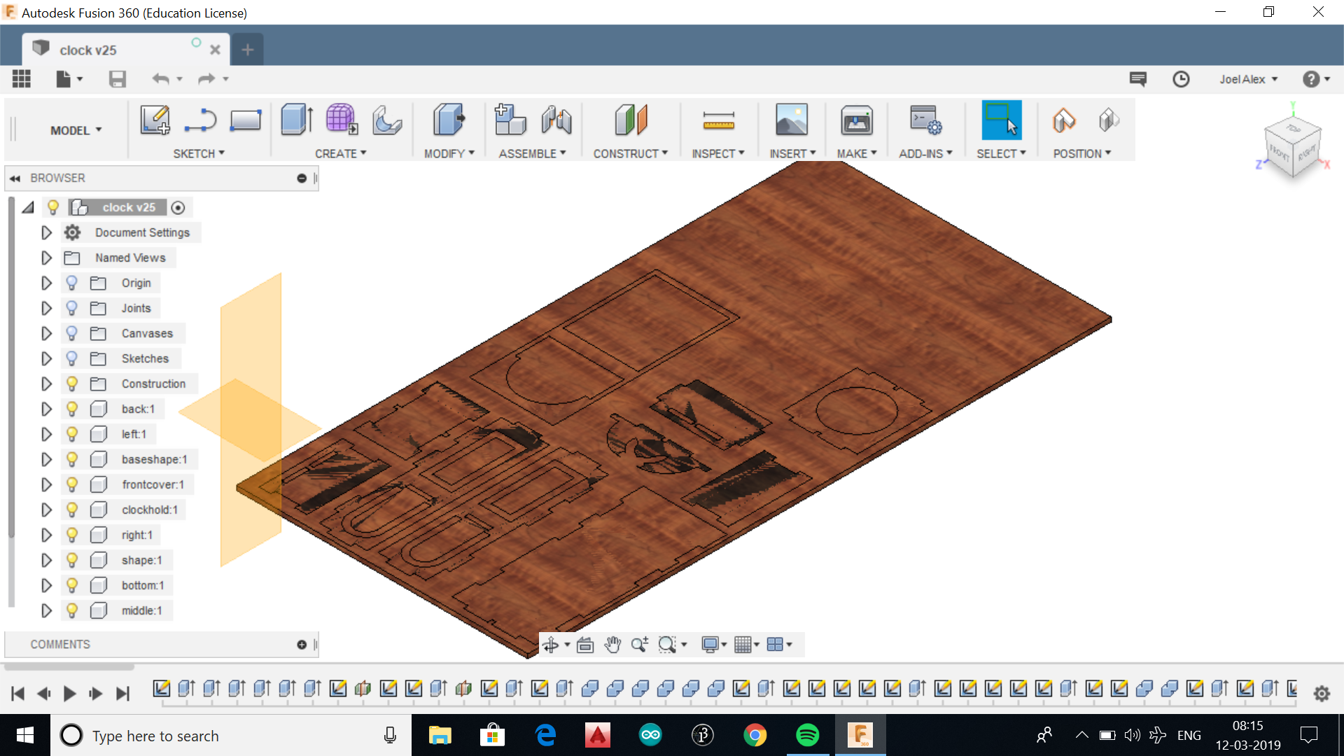
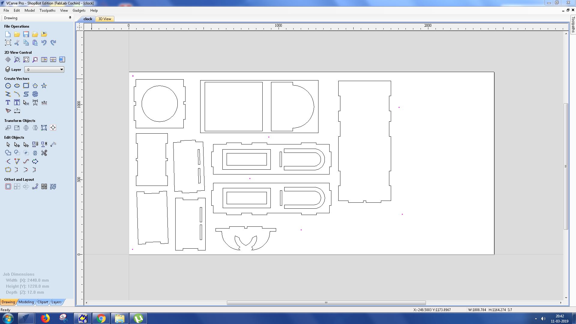
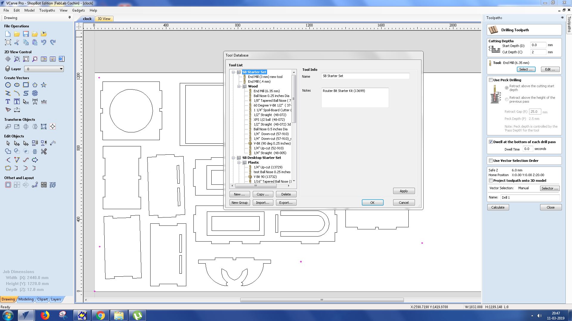
After completing the 3D design we need to place them in 2D plywood to be used in shopbot. To do that first we need to convert the bodies into components. All the bodies should be selected and right click them to convert to components. New components will be created with the same name of bodies. A new sketch should be created with the size of plywood and extrude it to the width of plywood, so that the components could be accomodated in them.
.
.
.
.
.
.
.
.
.
.
.
.
.
.
.
.png)
.
.
.
.png)
.
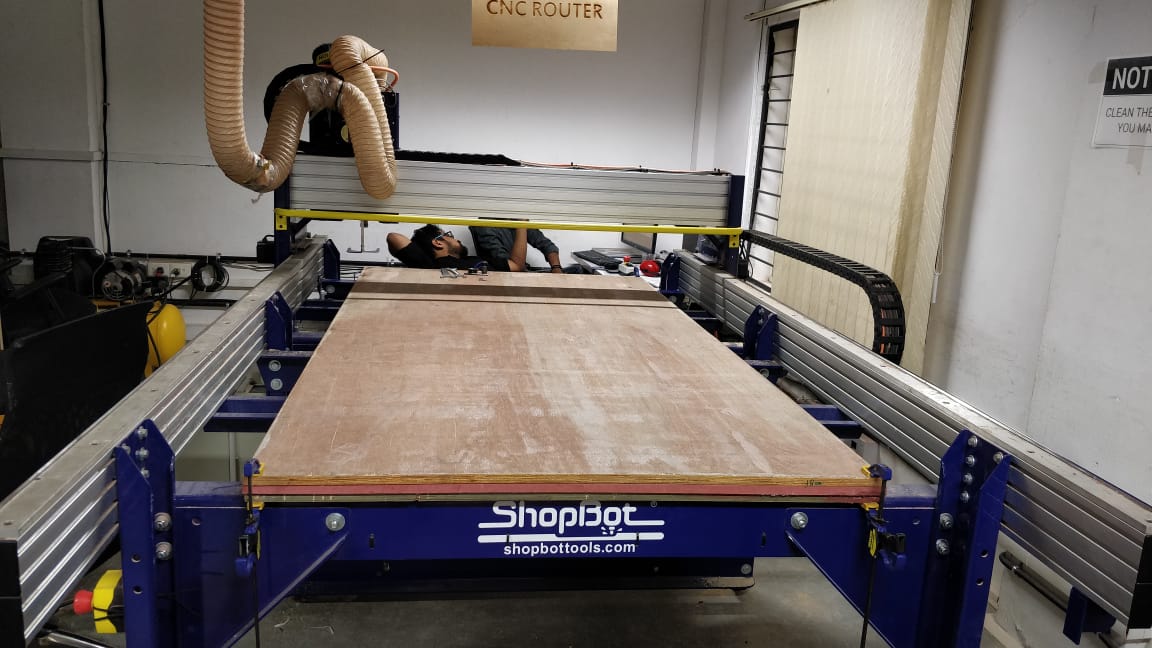
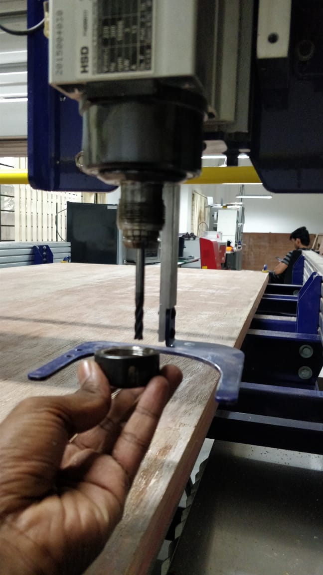
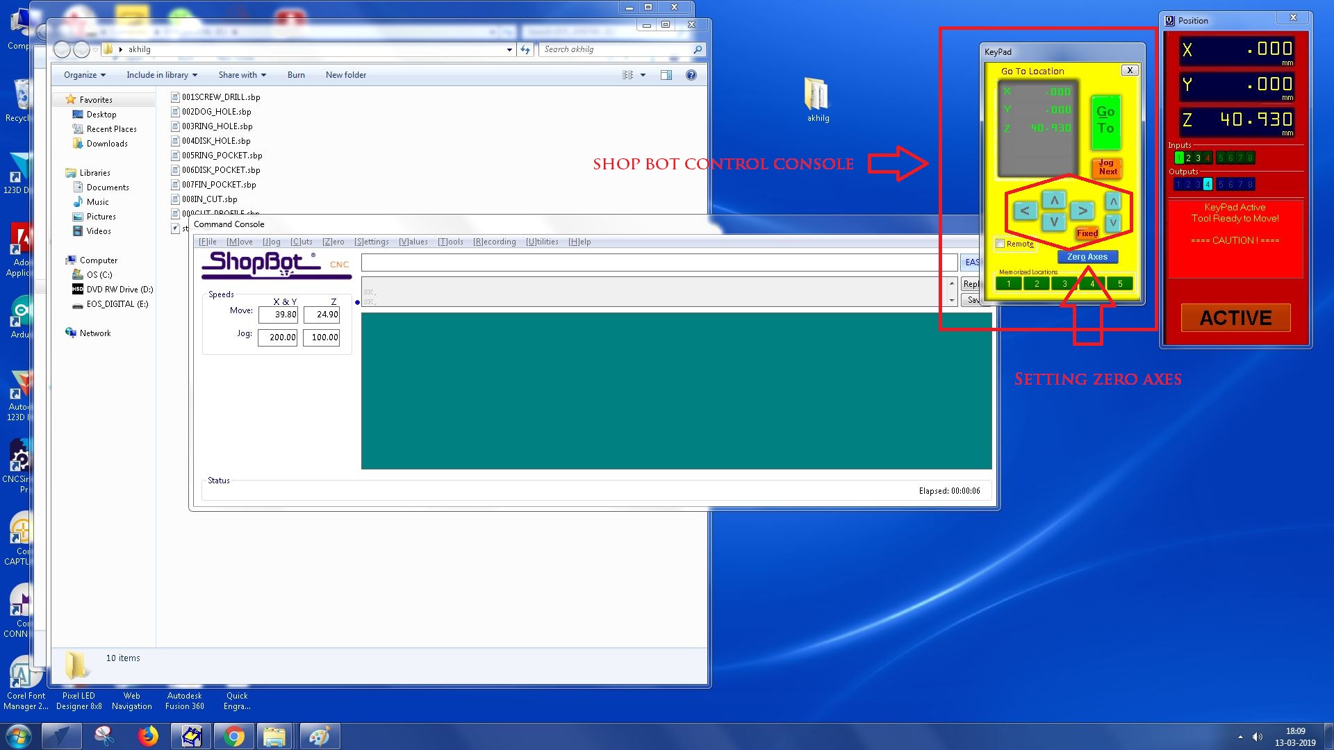
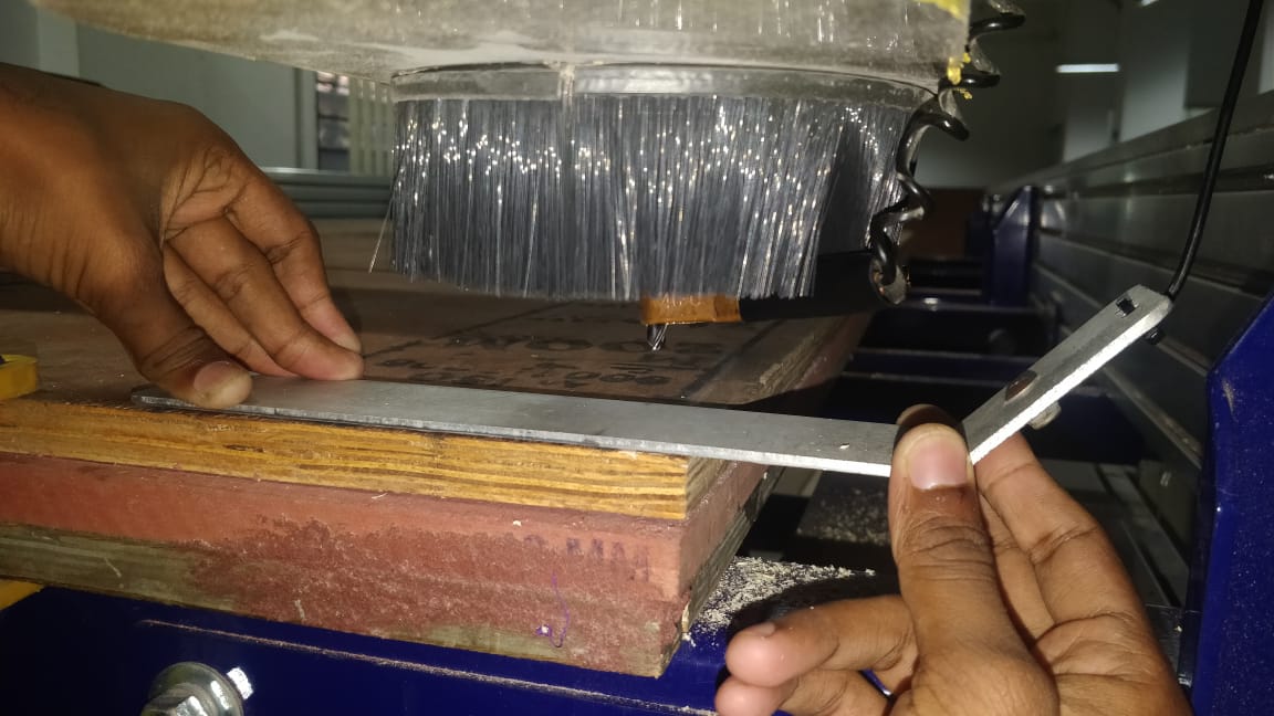
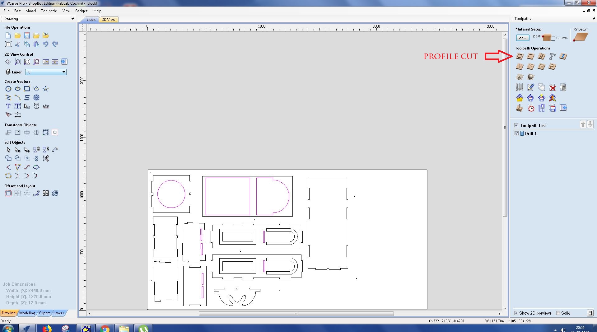
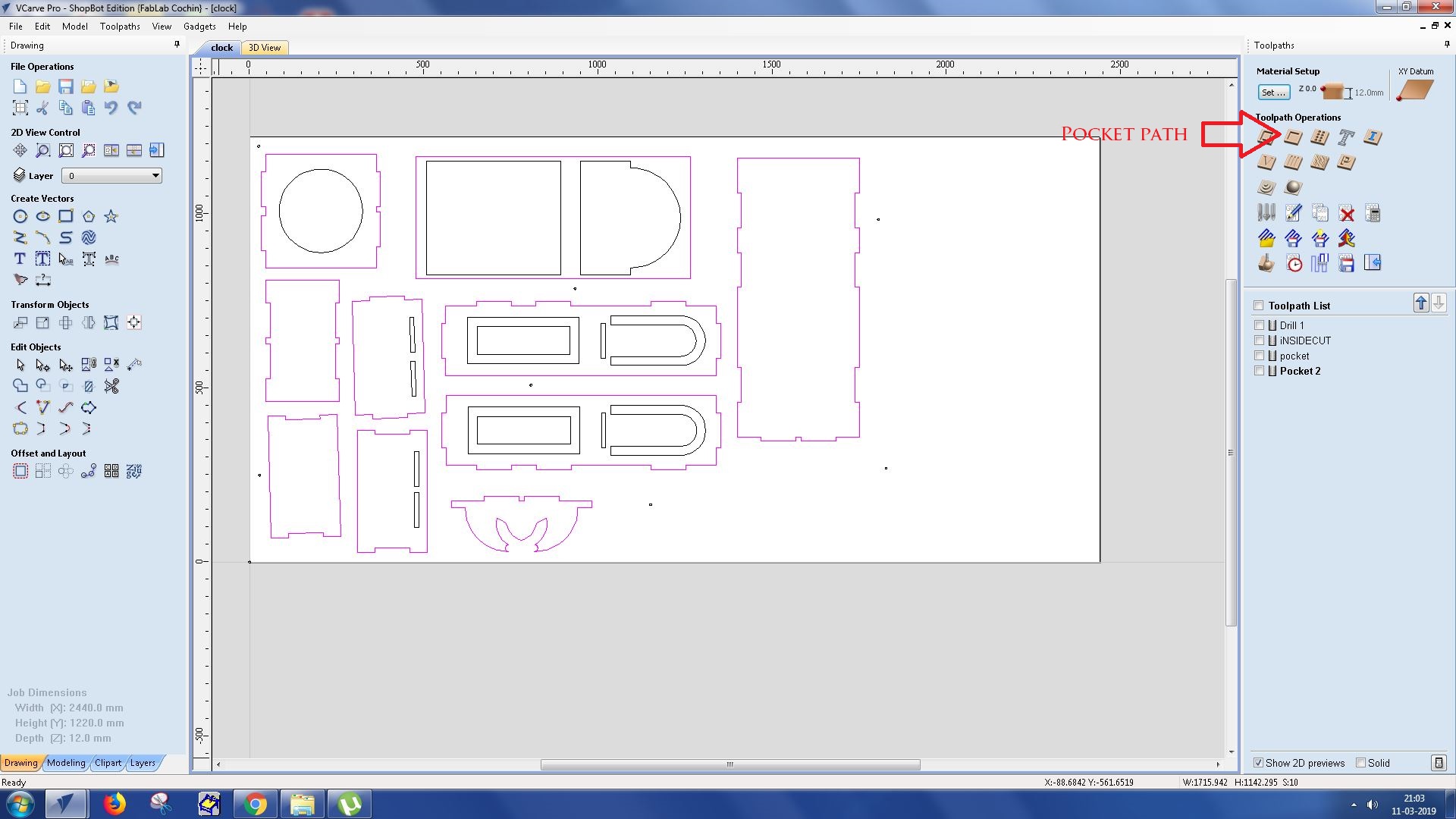
DXF file is now ready and we need to get it cut in shopbot. We could use fusion 360 CAM to cut the same directly. But here i am going to load the dxf file in V carve to get it cut. In V carve we need to set tool paths for the cutting. Commonly used tool paths are:
.
.
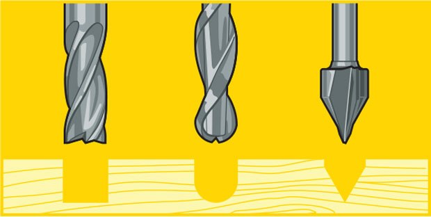
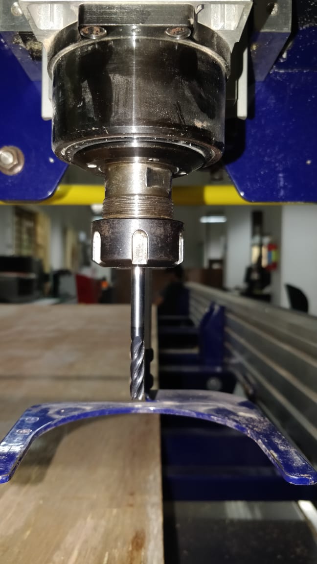
Each end mill tip shape is designed for a particular purpose. Some common cutter shapes are ballnose, fish tail, surface planing, v-carving, and straight. Ballnose mills produce a rounded pass and are ideal for 3D contour work, while fish tail cutters will produce a flat surface. V-bits produce a “V” shaped pass and are used for engraving, particularly for making signs.
.
.
.
.
The diagram above shows the difference in clearing path shape between a fish tail, ball nose and V tools. Ball nose mills are often selected when doing 3D contouring because their rounded edge reduces jagged steps when cutting several stepped layers. Ball nose mills can also be used to cut wide paths with rounded edges by reducing the step over amount (overlapping distance between) between passes. By overlapping steps, the central scallop shown in the diagram is eliminated.
.
.
.
.
.
.
.
.
.
.
.
.
.
.
.
.
.
.
.
.
.
.
.
.
.
.
.
.
.
.
.
.
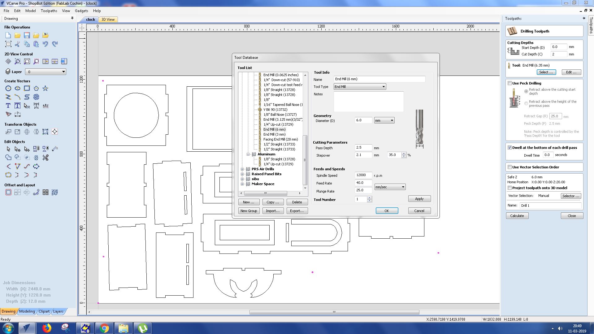
| Category | Description | Value |
|---|---|---|
| Tool type | Endmill | 6mm |
| Cutting parameter | Pass depth | 2.5 mm |
| - | Stepover | 2.1mm |
| Feeds and speeds | Spindle speed | 12000rpm |
| - | Feedrate | 40mm/sec |
| - | Plunge rate | 25mm/sec |
.
.
.
.
.
.
.
.
.
.
.
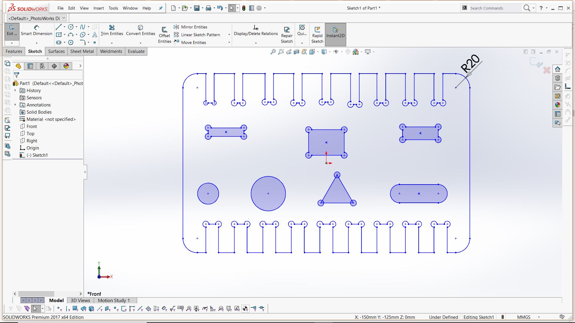
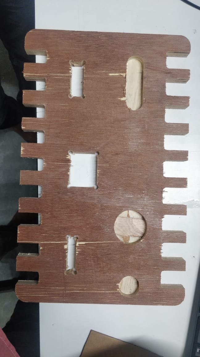
For group assignment all the types of cut paths were chosen. As shown below shapes of different sizes varying with 1mm was drawn in solidworks. The pockets, dogbones,profile cuts for innercuts, outercuts were all tested
.
.
.