
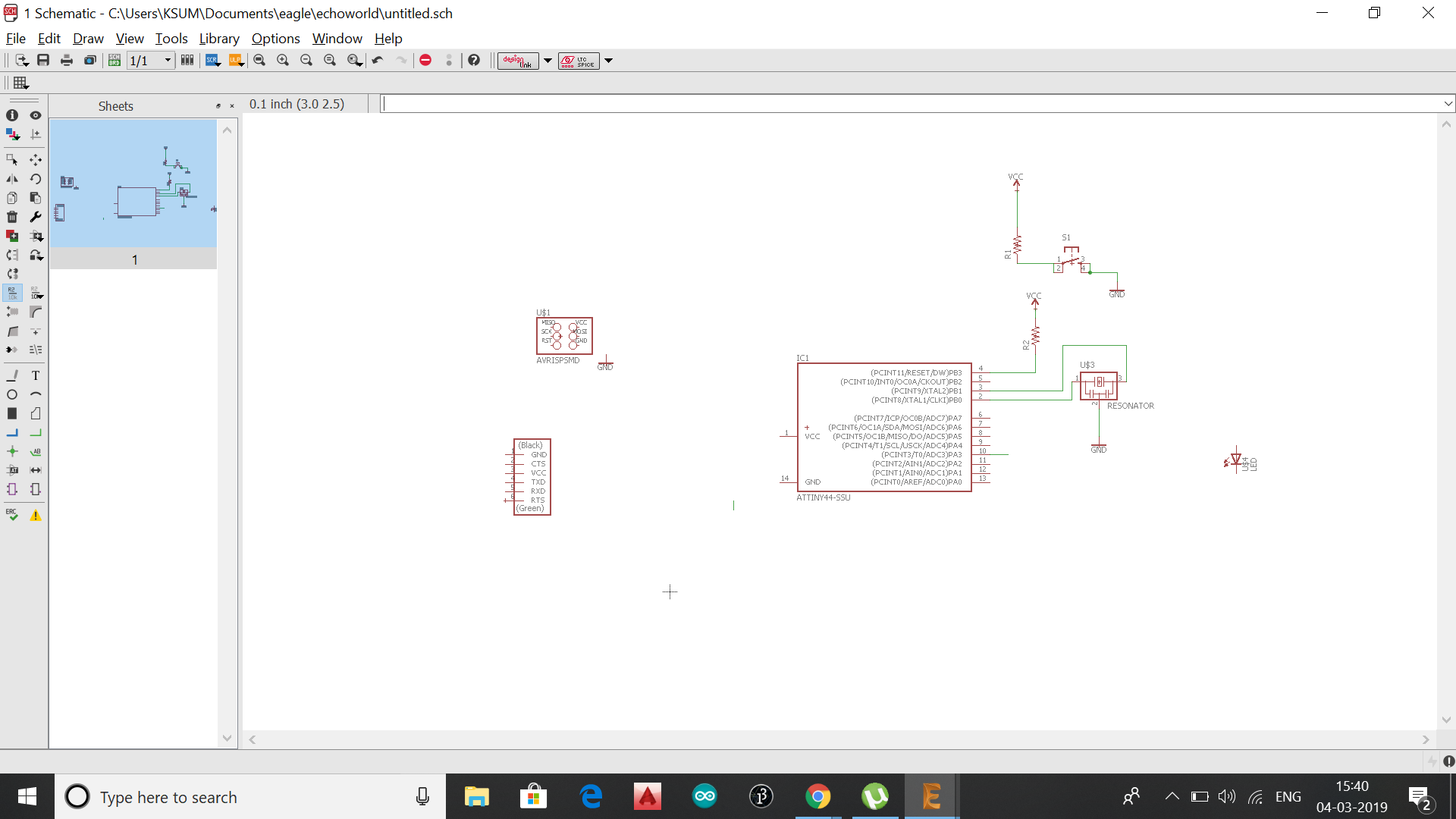
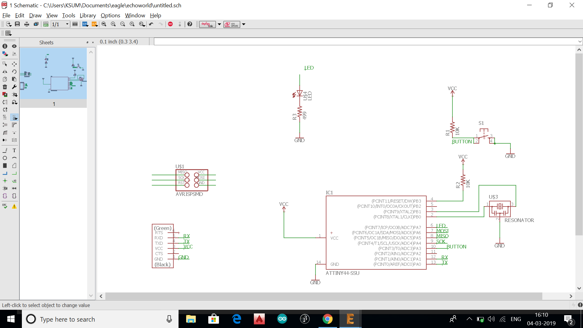
Redraw the echo hello-world board, add (at least) a button and LED (with current-limiting resistor), check the design rules, make it.
Get familiarised with the fab equipments
.
Even though i have studied Electrical & electronics engineering, my main focus subject was electrical. So i was not much familiar with designing electronics circuit.This was the main reason why i joined Fabacademy. So instead of copying others work i thought i would start from the basics. So i started reading electronics tutorials, youtube videos
.
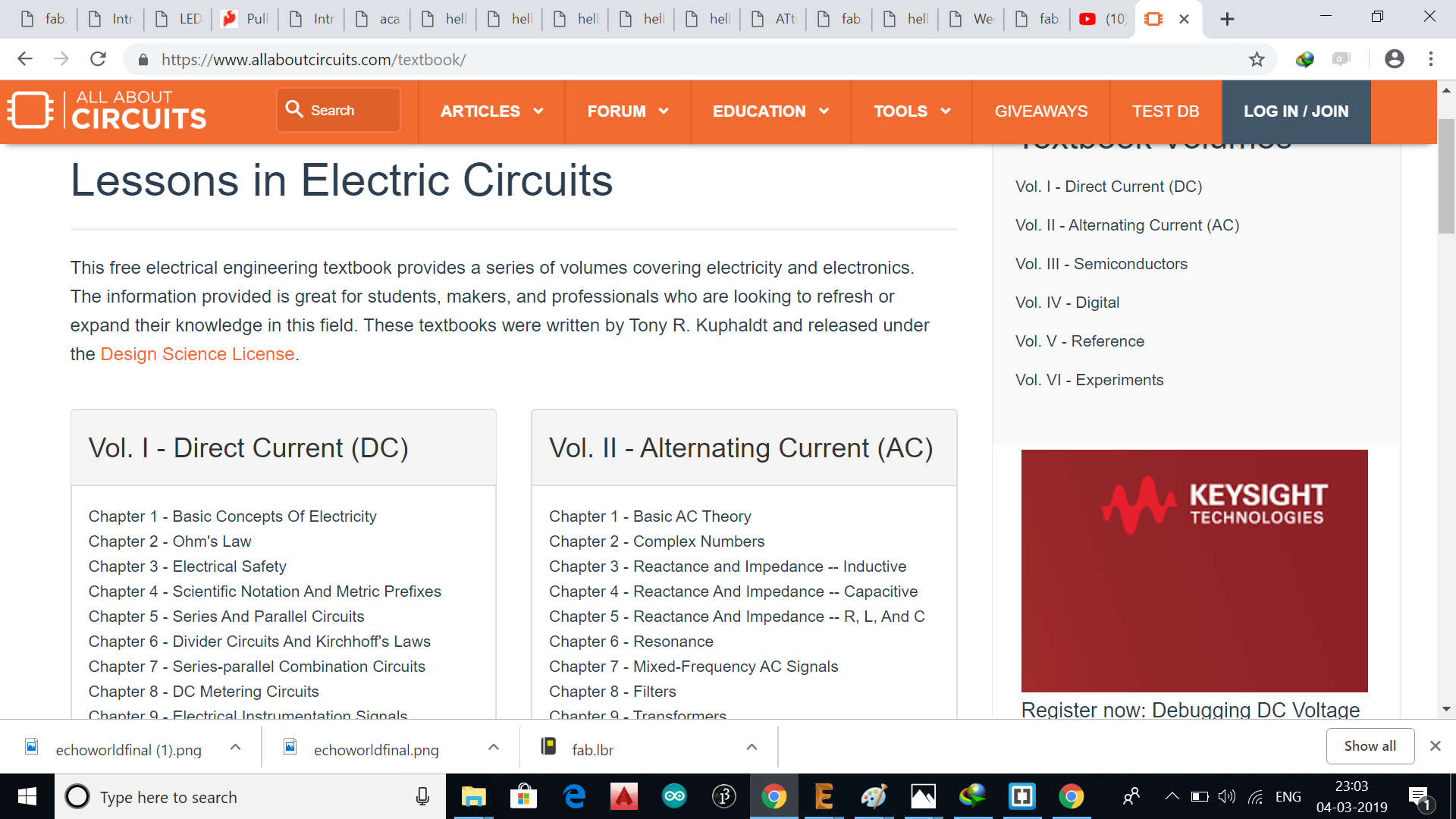
I started from www.allaboutcircuits.com , www.electronics-tutorials.ws
.
.
.
.
.
.
.
.
.
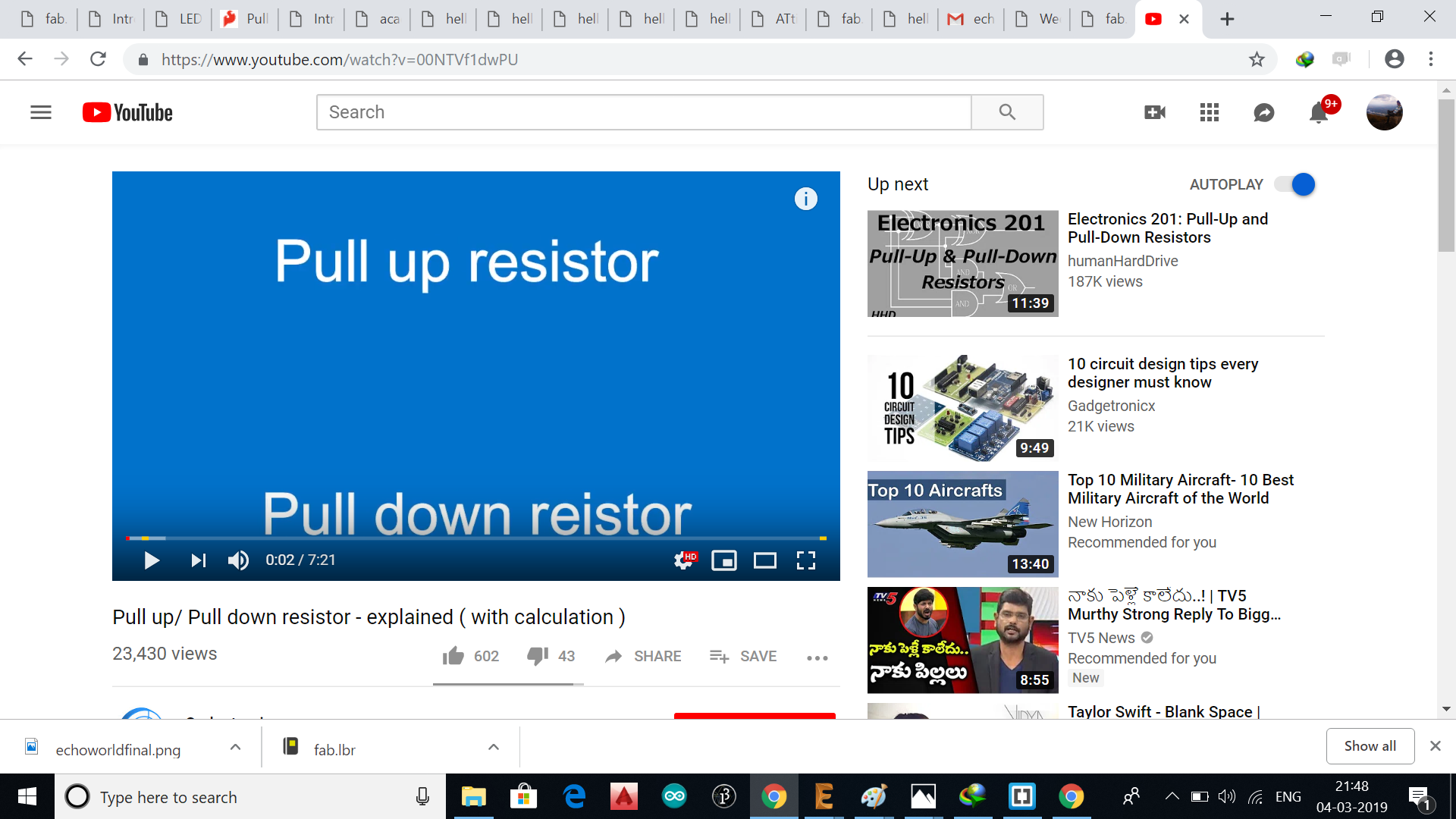
I gained an idea on electronics, diodes, pull up/down resistors after watching these tutorials So i decided to build a personal assistant/assistants with the shape of an owl in fusion 360
.
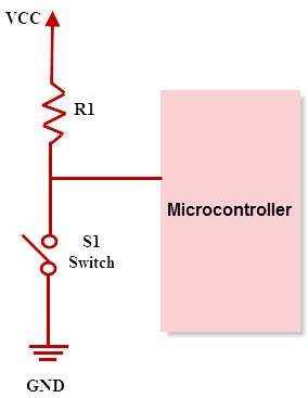
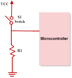
These resistors are used in digital logic circuits to ensure a logic level at a pin, which results in state wherein the input/output voltage is nonexistence driving signal. Digital logic circuits consist of three states like high, low and floating or high impedance. When the pin is not pulled to a lower or a high logic level, then the high impedance state occurs. These resistors are used to solve the problem for the microcontroller by pulling the value to a high state.When the switch is open, the microcontrollers input would be floating and brought down only when the switch is closed.
.
.
As pull up resistors, Pull-down resistors also works in the same way. But, they pull the pin to a low value. Pull-down resistors are connected between a particular pin on a microcontroller and the ground terminal. An example of a pull down resistor is a digital circuit shown in the figure below. A switch is connected between the VCC and the microcontroller pin. When the switch is closed in the circuit, the input of the microcontroller is logic 1, but when the switch is open in a circuit, the pull down resistor pulls down the input voltage to the ground (logic 0 or logic low value). The pull down resistor should have a higher resistance than the impedance of the logic circuit.
.
.
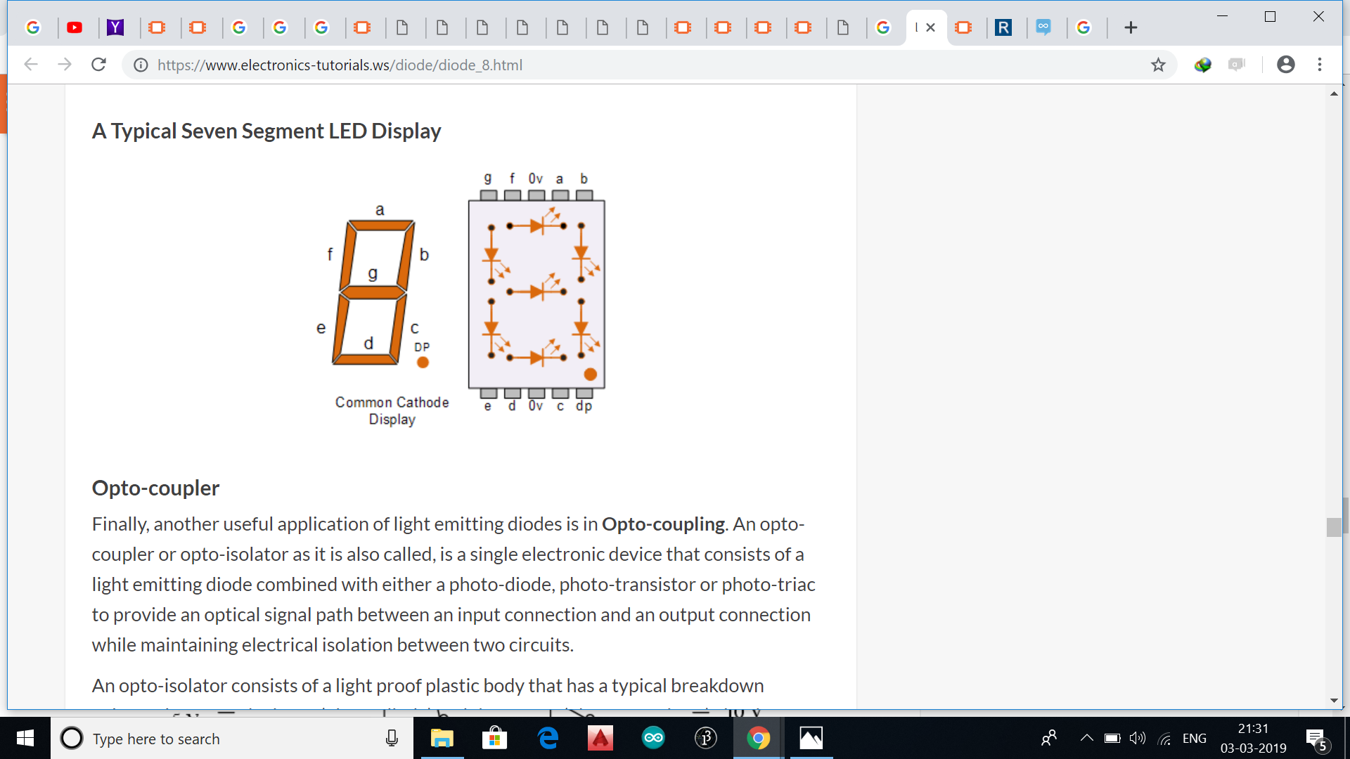
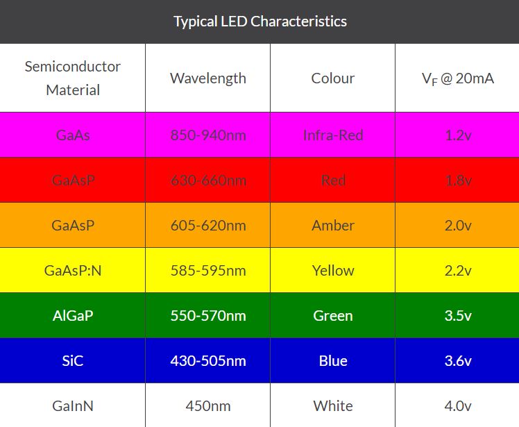
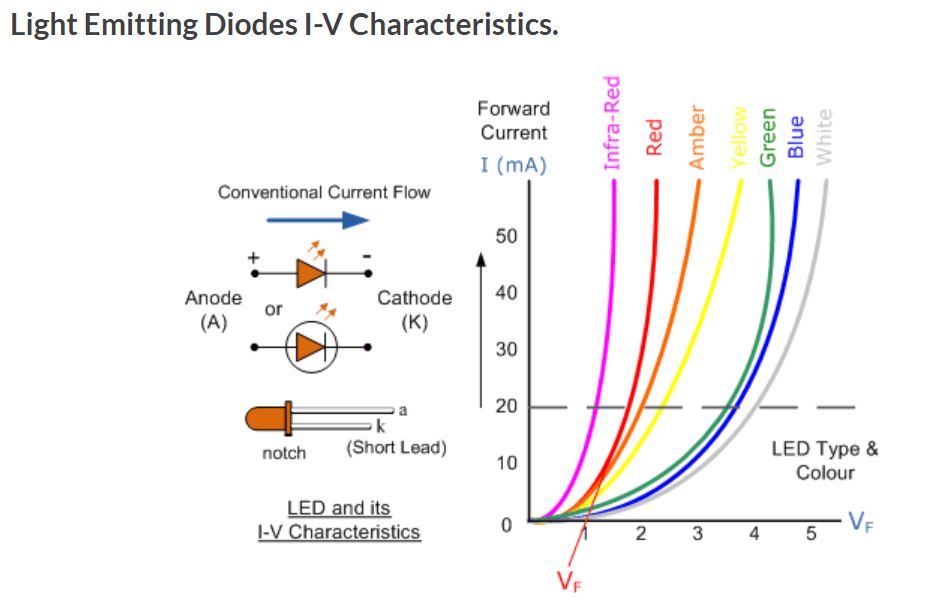
Light Emitting Diodes are semiconductor devices that convert electrical energy into light energy. Light Emitting Diodes are made from exotic semiconductor compounds such as Gallium Arsenide (GaAs), Gallium Phosphide (GaP), Gallium Arsenide Phosphide (GaAsP), Silicon Carbide (SiC) or Gallium Indium Nitride (GaInN) all mixed together at different ratios to produce a distinct wavelength of colour.
.
.
.
.
.
.
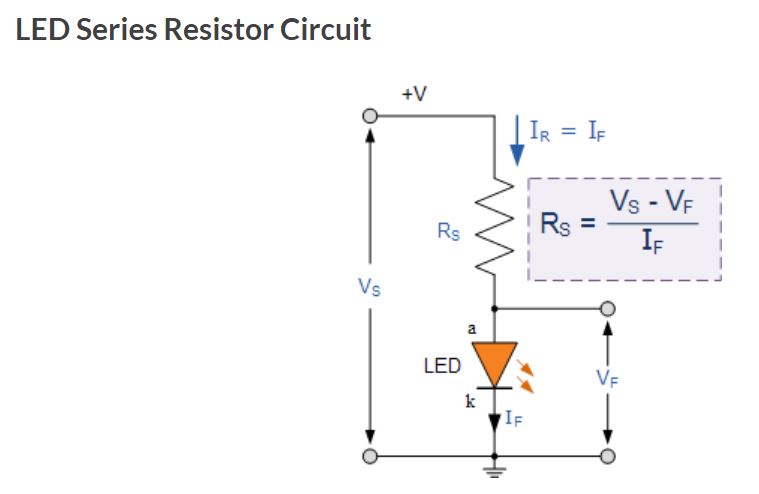
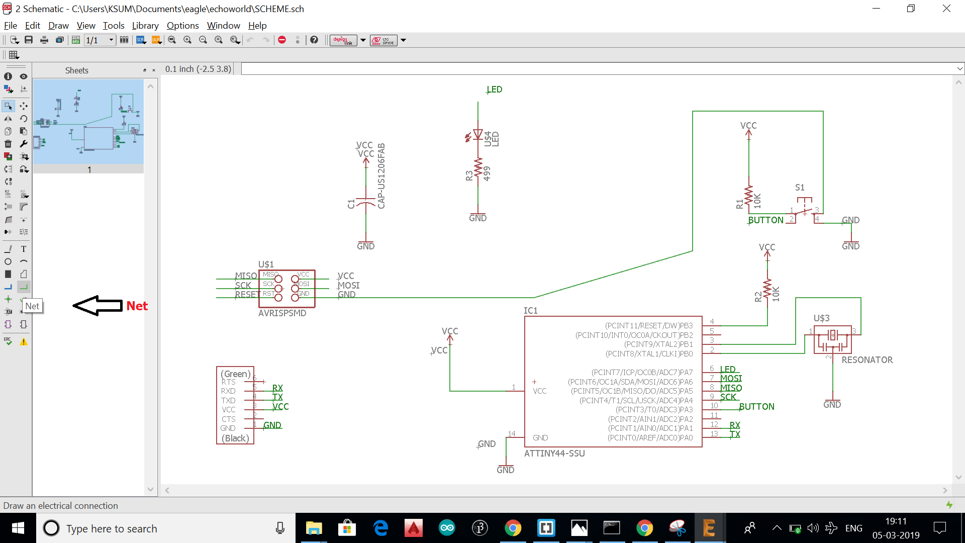
The above figure is a typical led connection where .Rs is the Series resistance ,Vs is the source voltage,Vf is the forward voltage of the LED(also referred to as the "voltage drop") ,If is the safe current through the LED
So we have
Vs = supply voltage =5v
Vf = 1.8V
If = 18mA
So Rs = (5 - 1.8)/(.018) = 177.77
The closest resistor having a greator value than this in our lab is 499 ohm . i hope may be this work with a reduced brightness.
.
.
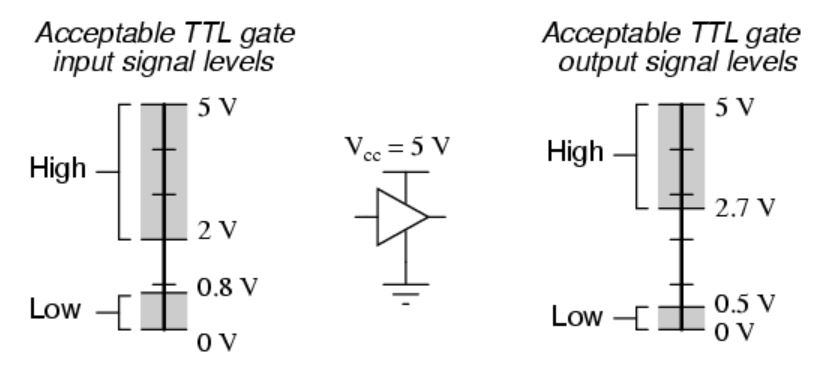
TTL gates operate on a nominal power supply voltage of 5 volts, +/- 0.25 volts. Ideally, a TTL “high” signal would be 5.00 volts exactly, and a TTL “low” signal 0.00 volts exactly. However, real TTL gate circuits cannot output such perfect voltage levels, and are designed to accept “high” and “low” signals deviating substantially from these ideal values. “Acceptable” input signal voltages range from 0 volts to 0.8 volts for a “low” logic state, and 2 volts to 5 volts for a “high” logic state. “Acceptable” output signal voltages (voltage levels guaranteed by the gate manufacturer over a specified range of load conditions) range from 0 volts to 0.5 volts for a “low” logic state, and 2.7 volts to 5 volts for a “high” logic state:
.
.
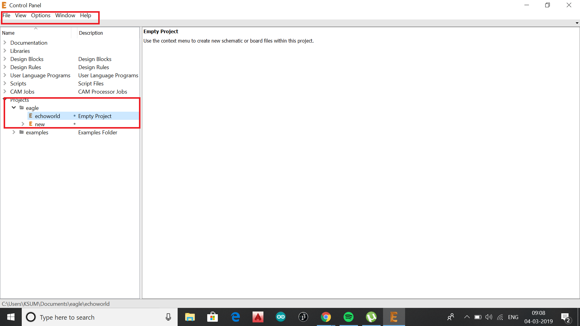
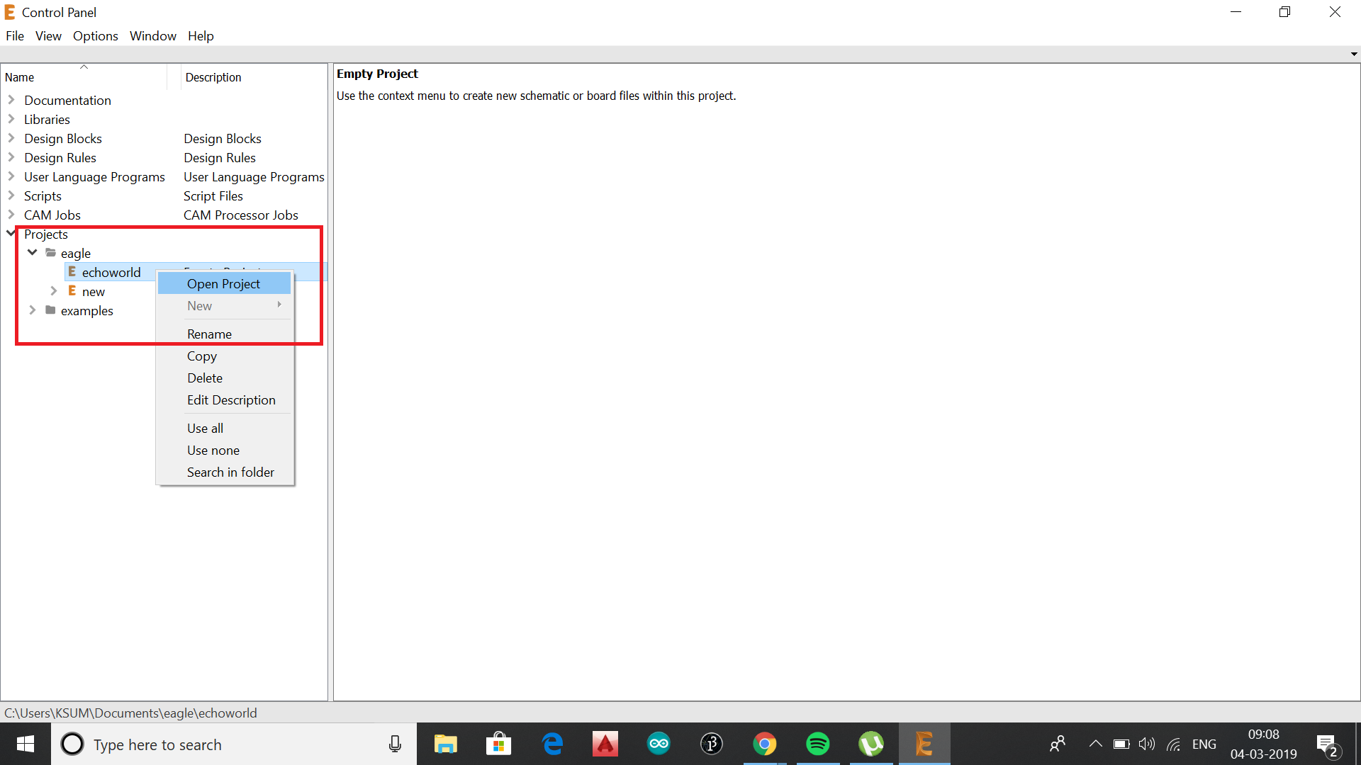
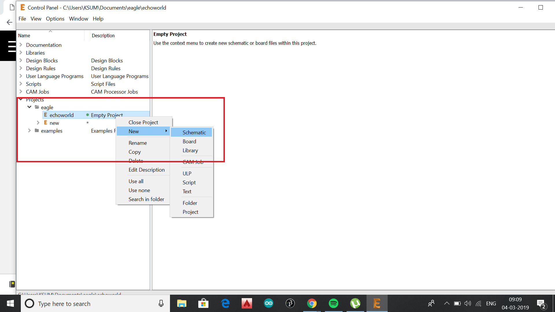
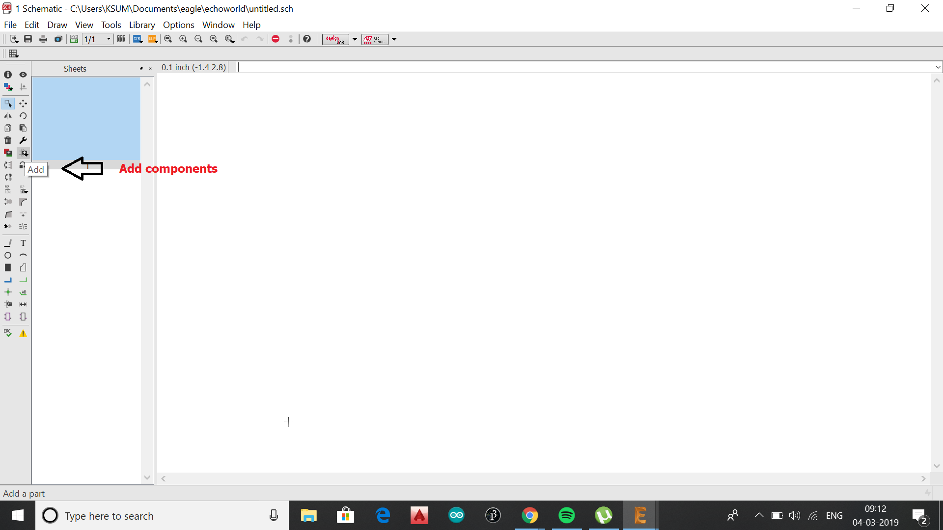
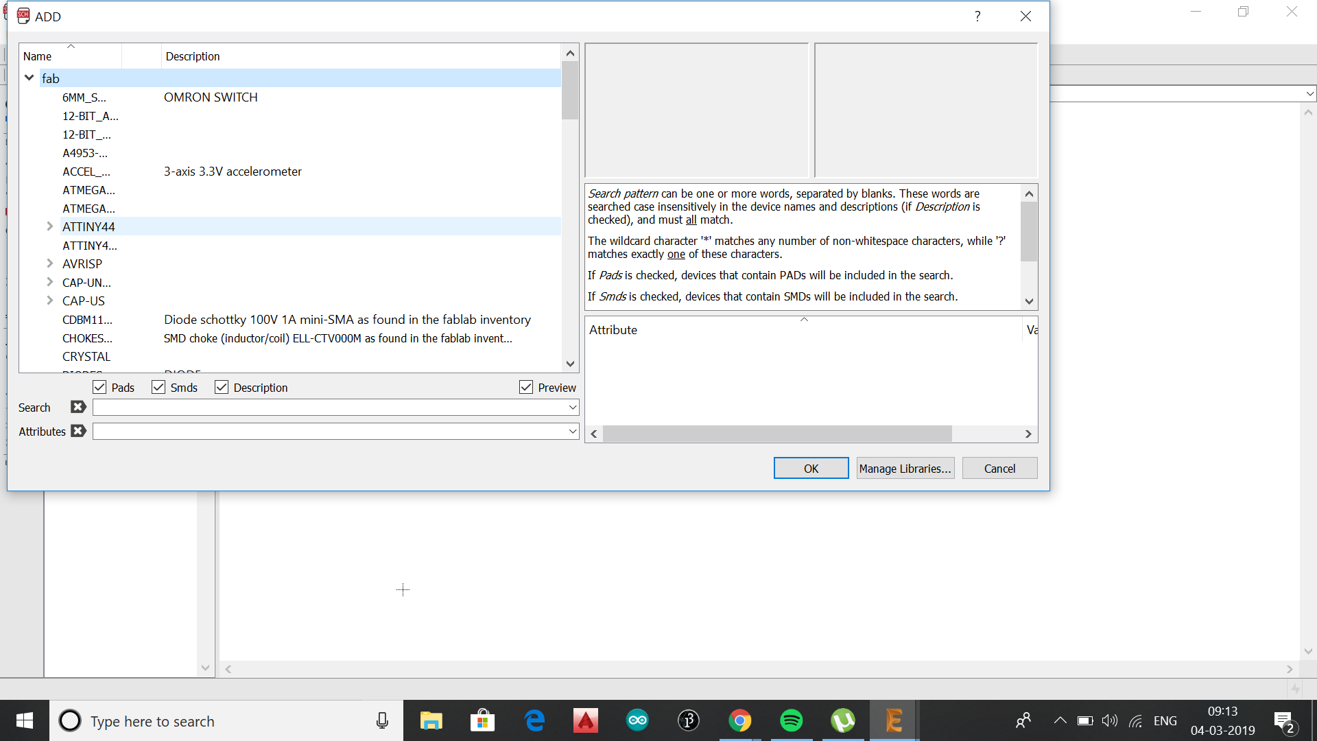
Autodesk EAGLE is an electronic design automation (EDA) software. Enabling printed circuit board (PCB) designers to seamlessly connect schematic diagrams, component placement, PCB routing and comprehensive library content.
.
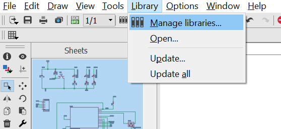
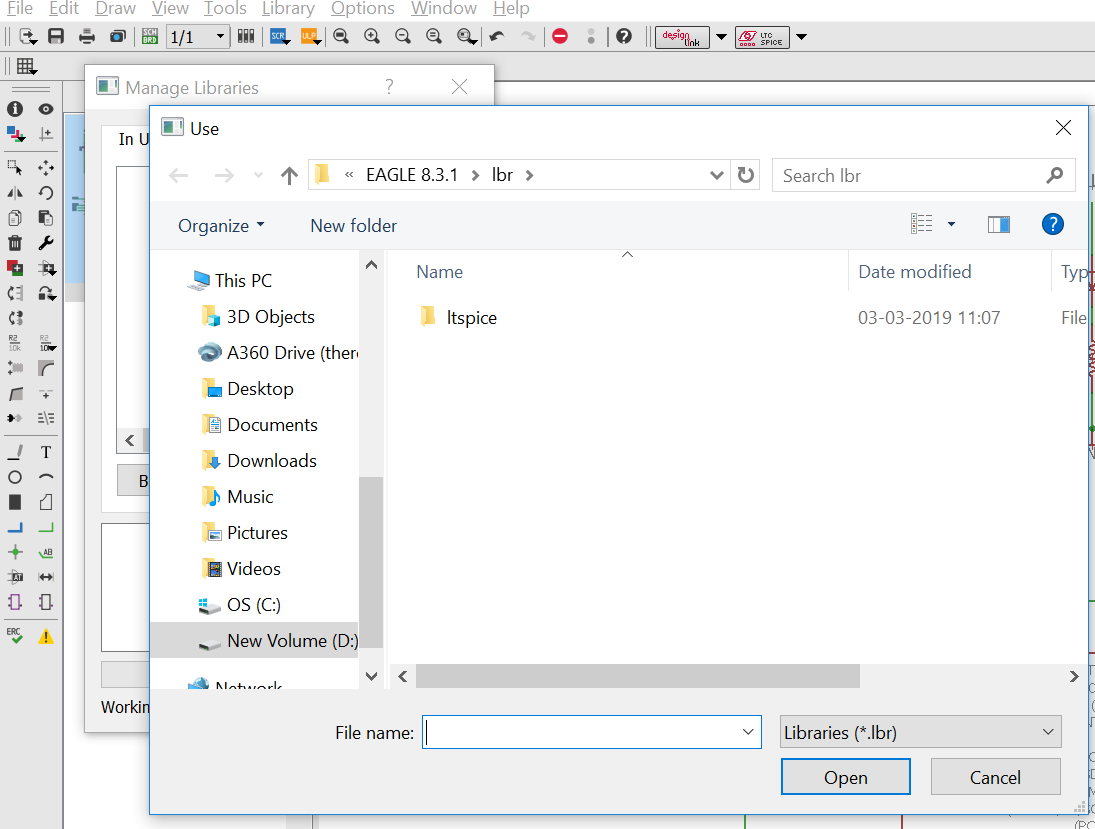
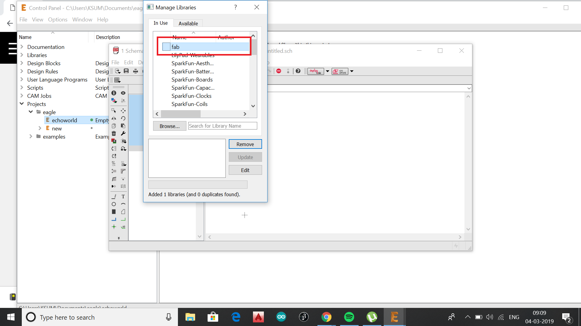
Eagle has got many inbuilt libraries. The libraries that can be used with fablab can be accessed here fablibrary
.
.
.
.
.
.
.
.
.
.
.
.
.
.
.
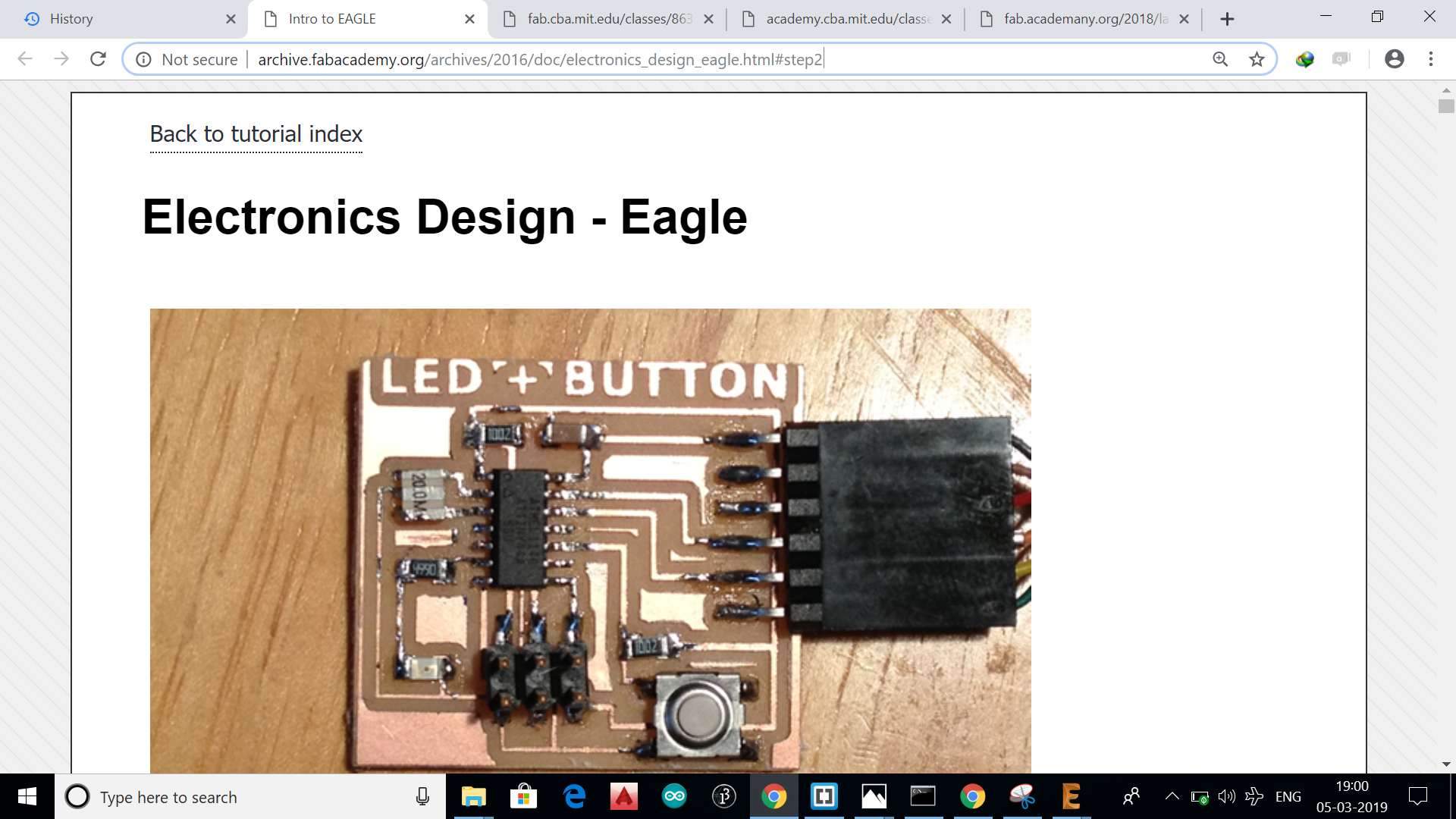
The tutorial from fabacademy docs link here really felt very much useful as it explained a lot and was a hand book for the week, i found that it was very well explained. So i decided to followed the same.
.
.
.
.
.
.
.
.
.
.
.
.
.
.
s.
.
.
.
.
.
.
.
.
.
.
.
.
.
.
.
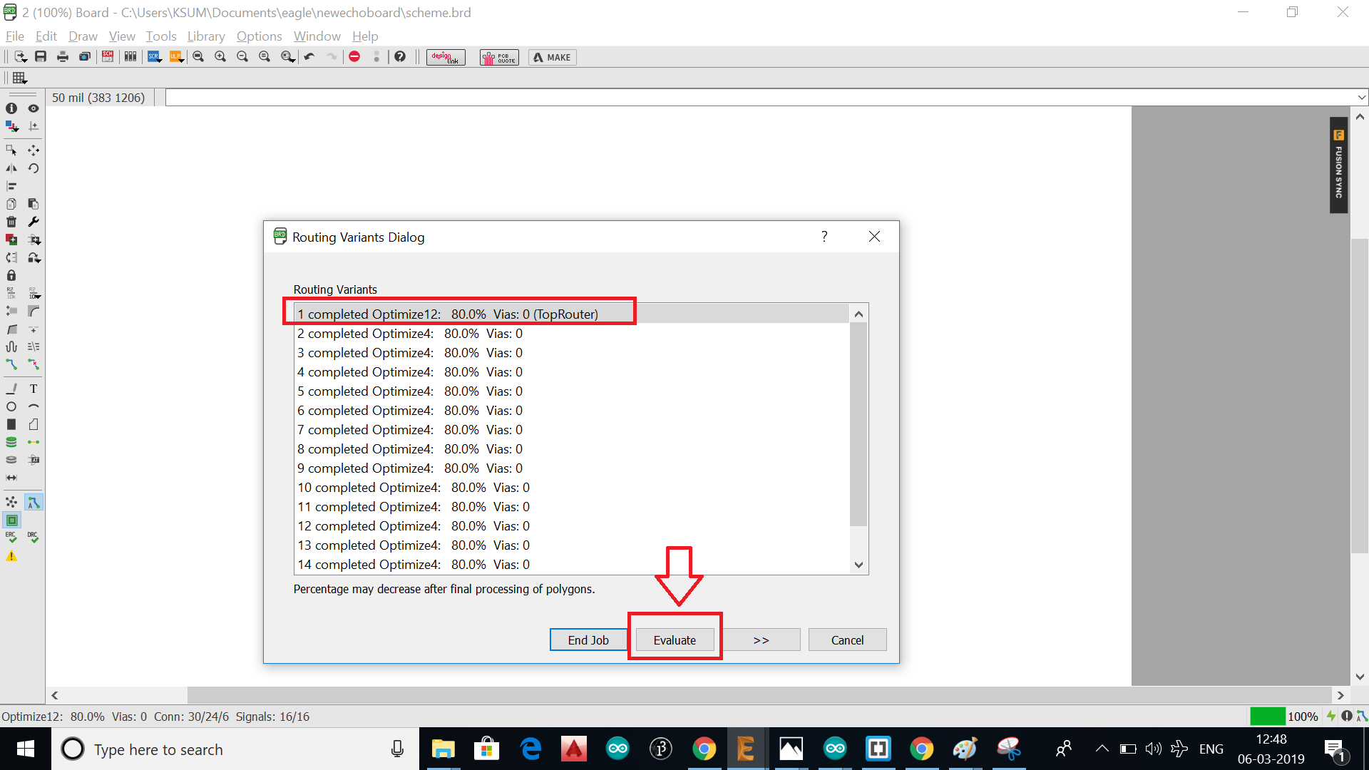
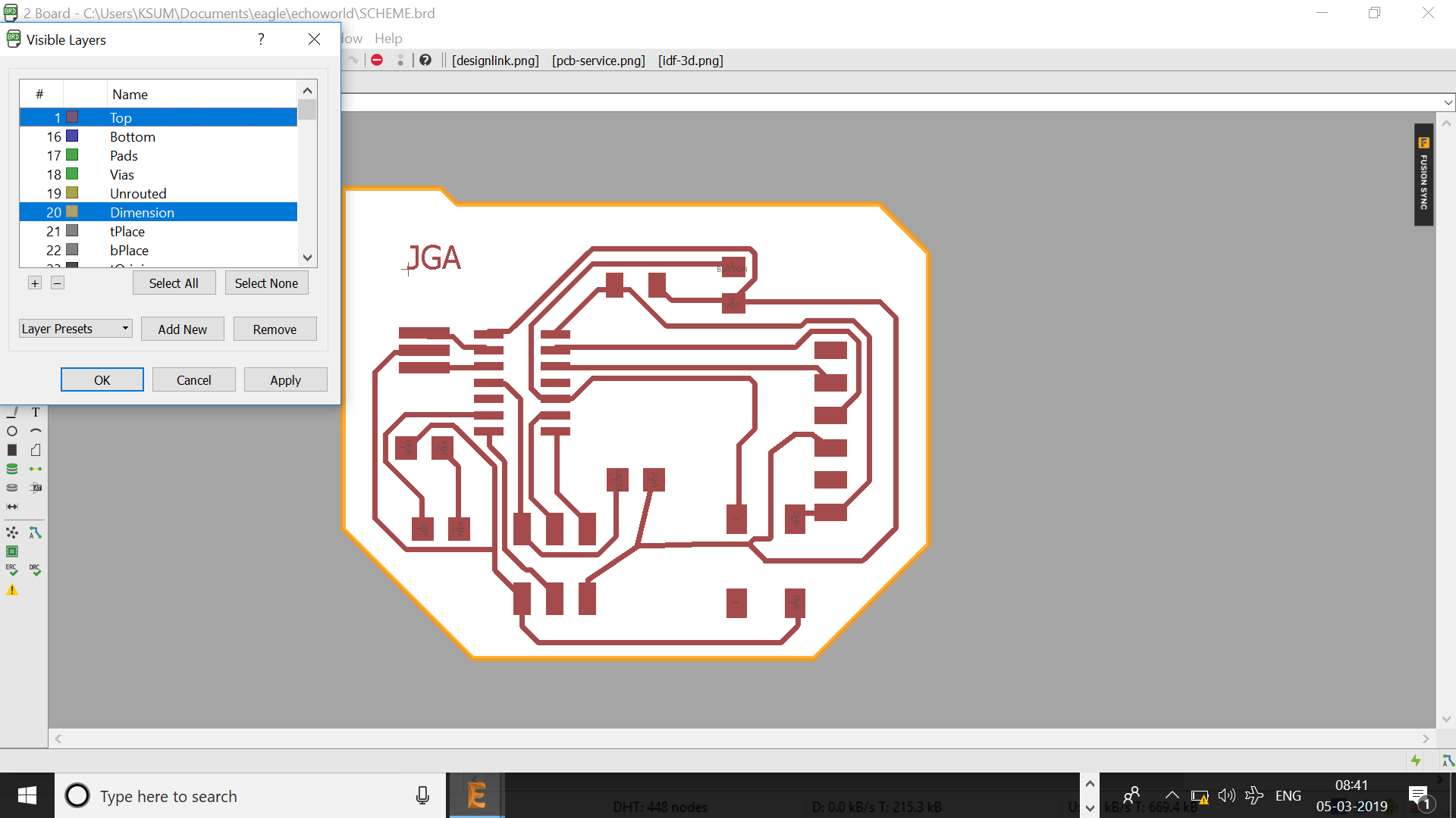
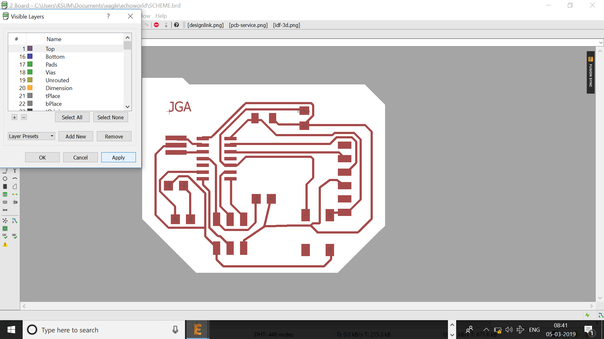
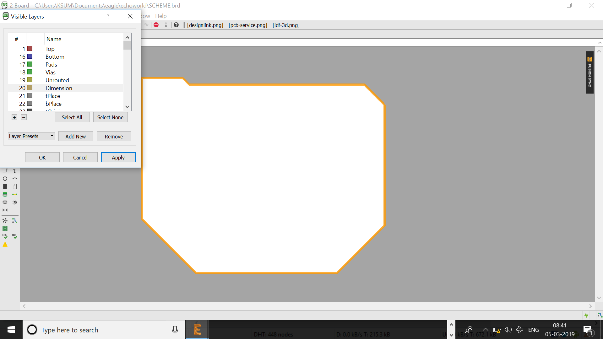
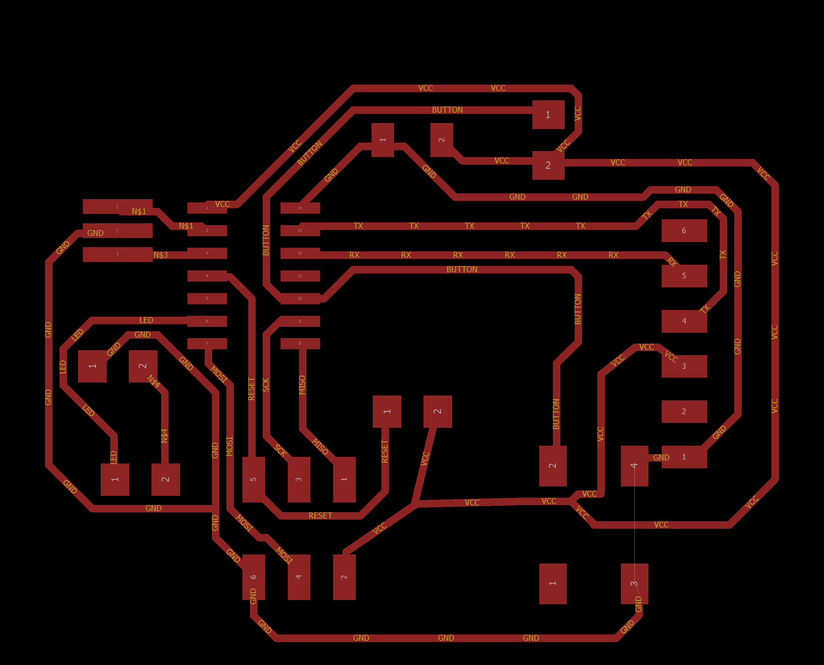
After 100% routing add name outer line etc in different layers as shown below.
.
.
.
.
.
.
.
.
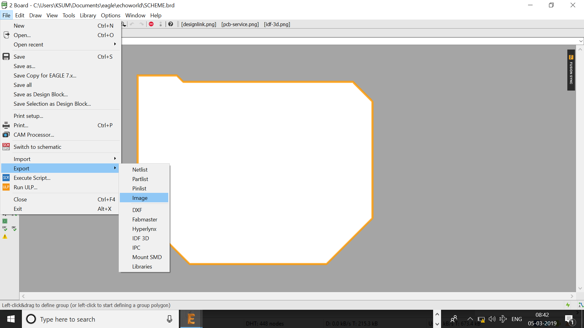
Download the file here
.
.
.
.
.
.
.
.
.
.
.
.
.
.
.
.
.
.
.
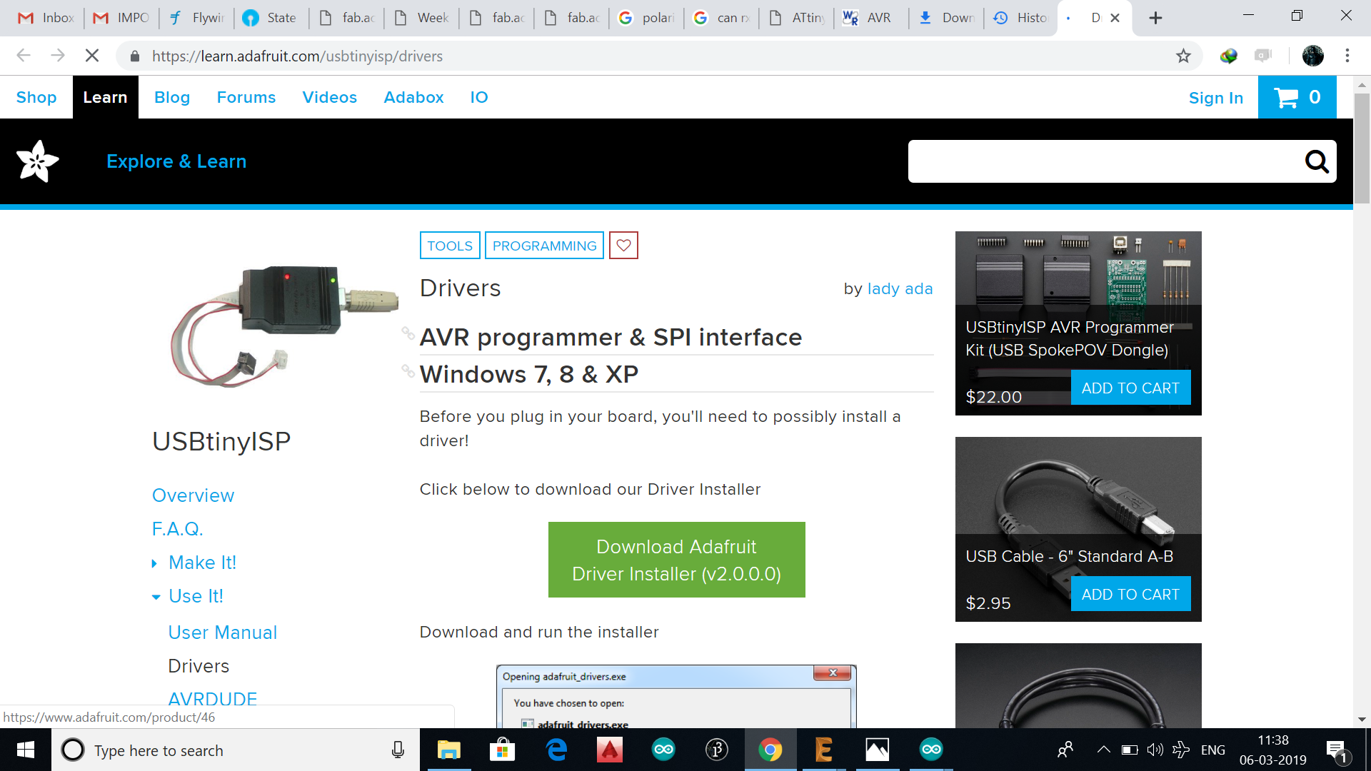
After soldering the components to the board,i decided to program using my USBattiny ISP which was made as previous week assignment.
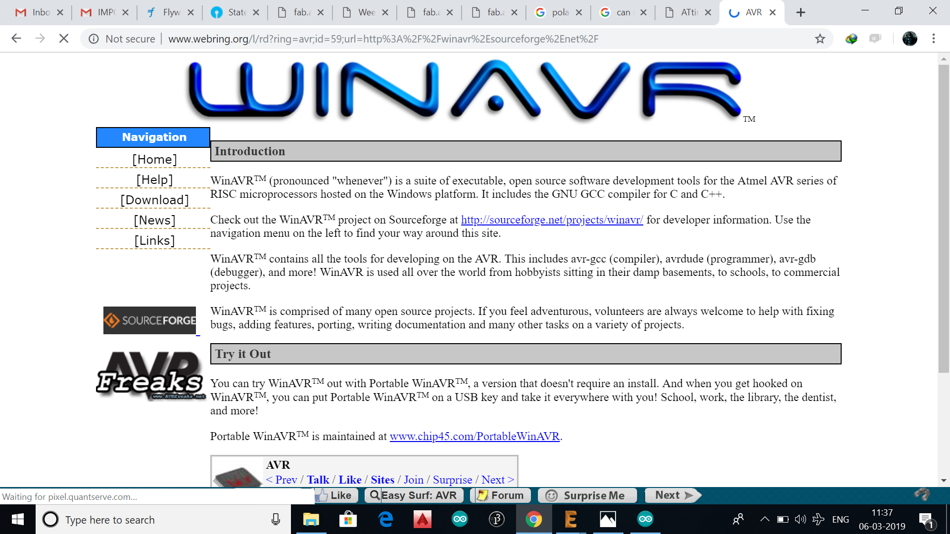
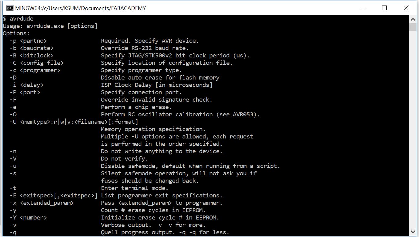
Since i used windows pc, before programming with the Usb attiny ISP, i downloaded the necessary drivers,WinAVR for windows. I used GIT bash for executing the linux commands in my windows PC
.
.
.
.
.
.
.
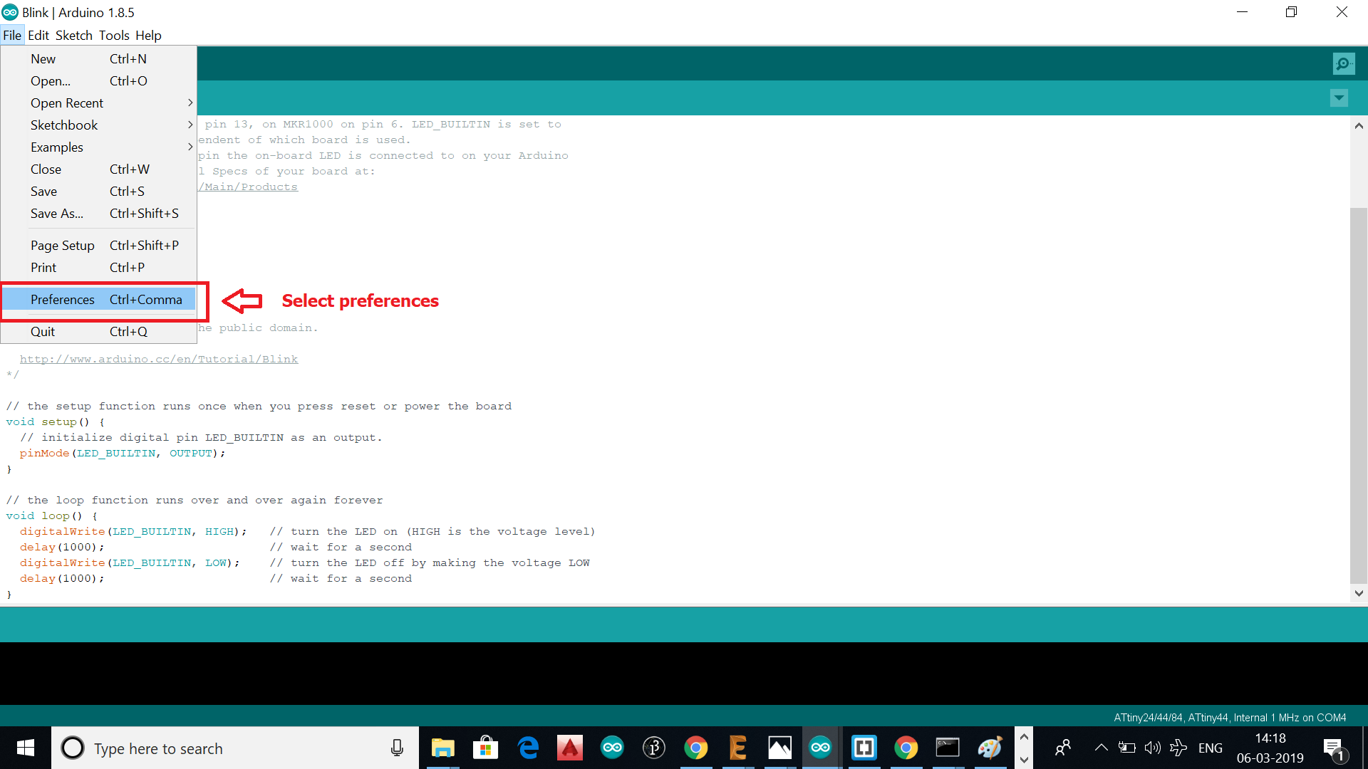
Since coding in arduino IDE was simple i thought i would use the same
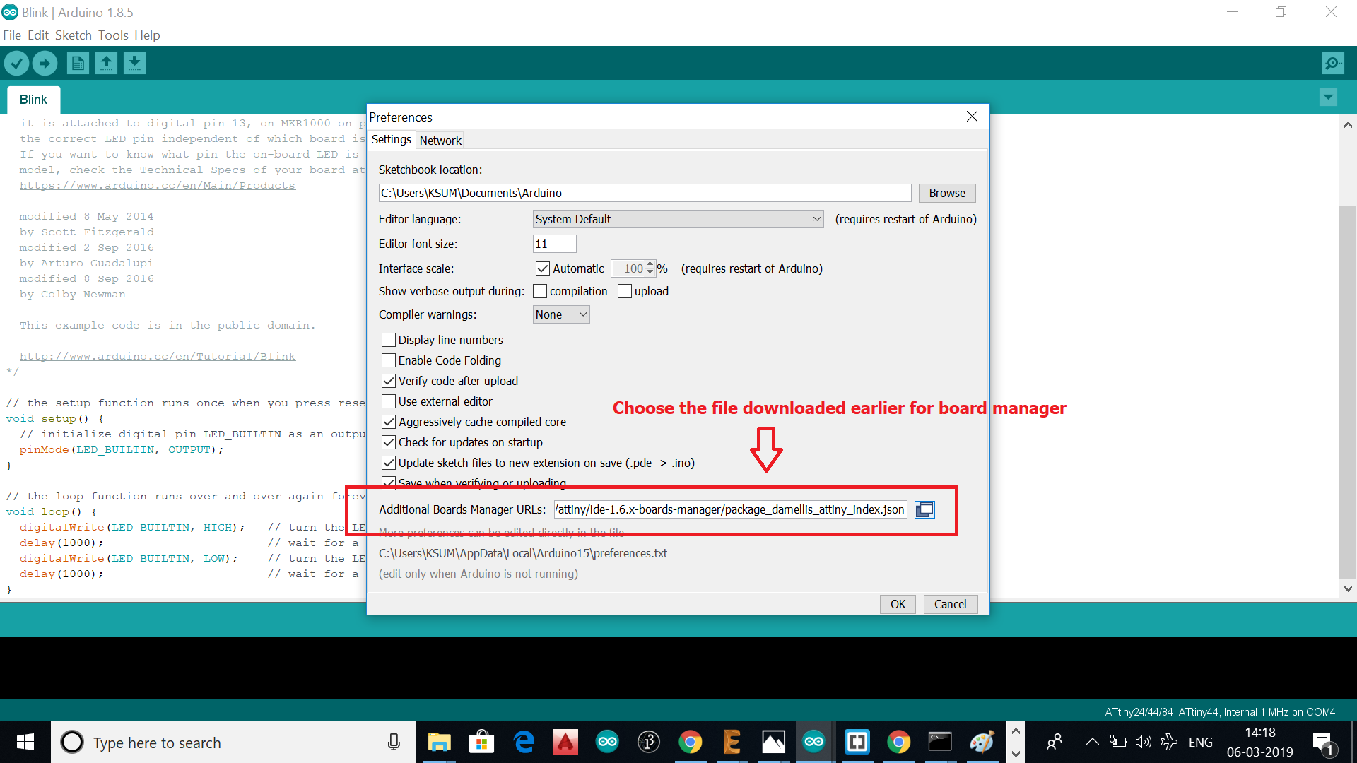
But as the arduino doesn't support the attiny44 board for programming, i added it using the board manager. The file shown in the link below was added to the board manager
https://raw.githubusercontent.com/damellis/attiny/ide-1.6.x-boards-manager/package_damellis_attiny_index.json
.
.
.
.
.
.png)
.
.
.png)
.
.
.png)
.
.
.png)
.
.
.
.
.
.
.png)
.
.
.png)
.
.
.png)
.
.
DESIGN FILES FOR DOWNLOADHERE
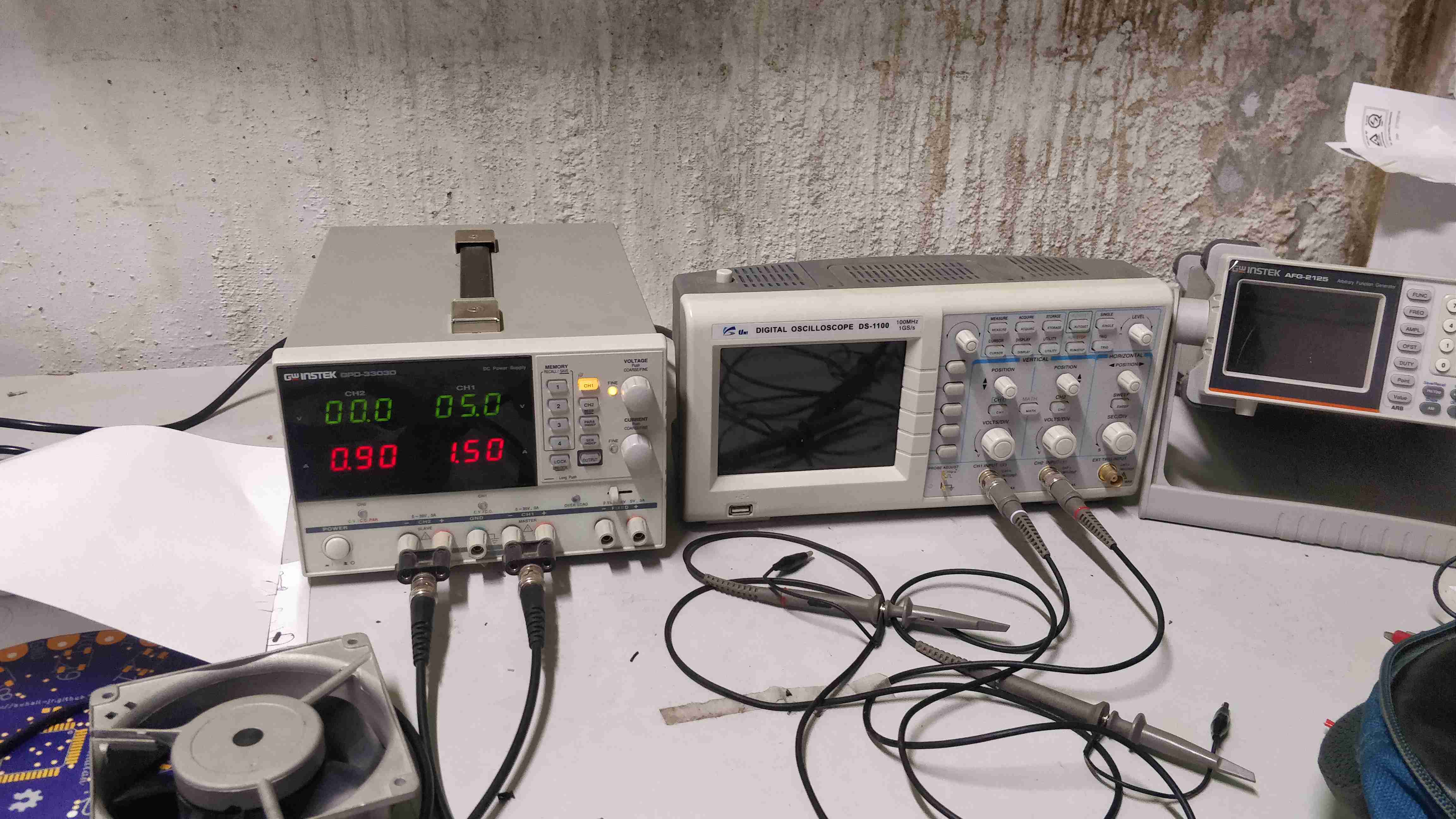
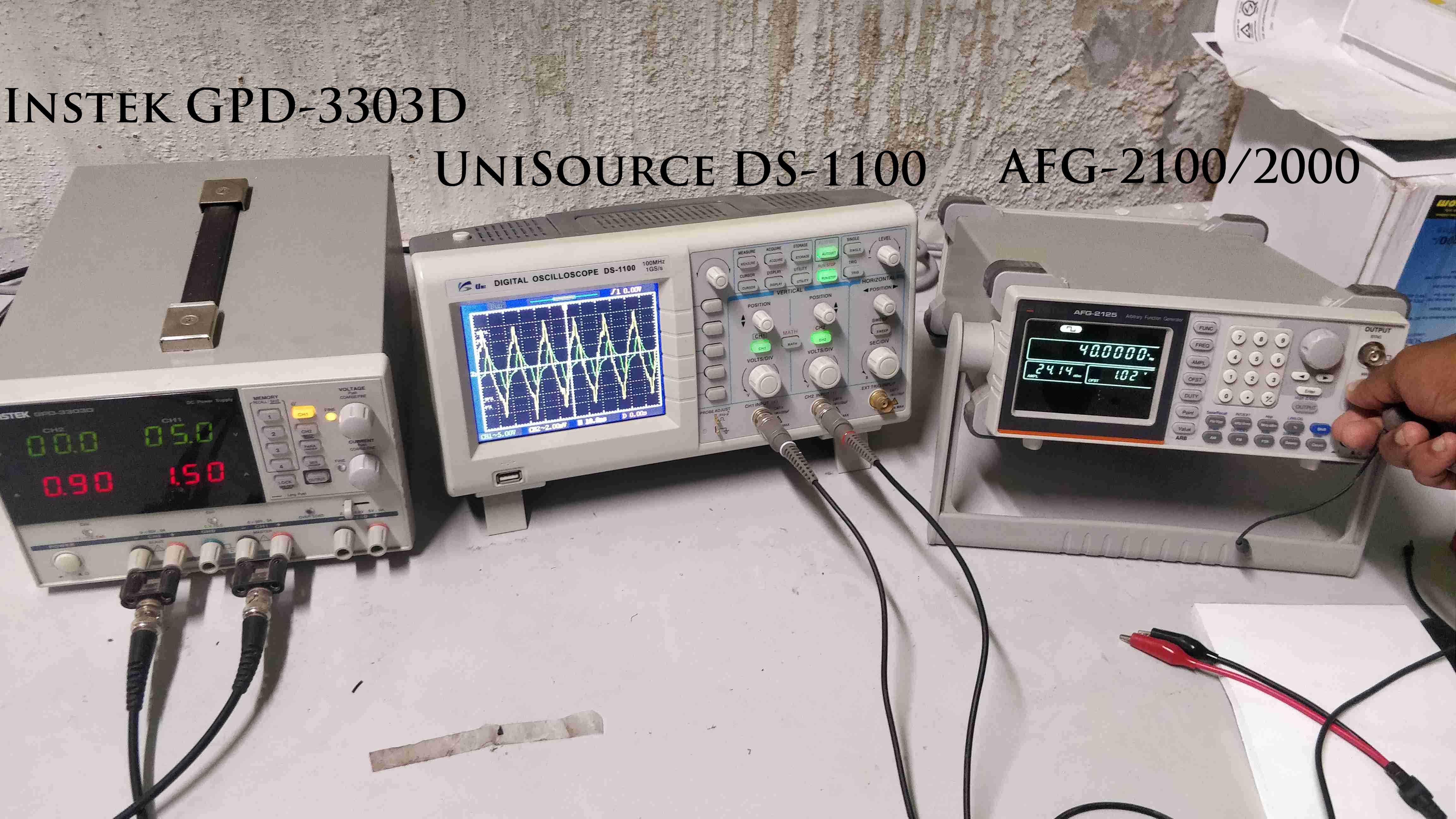
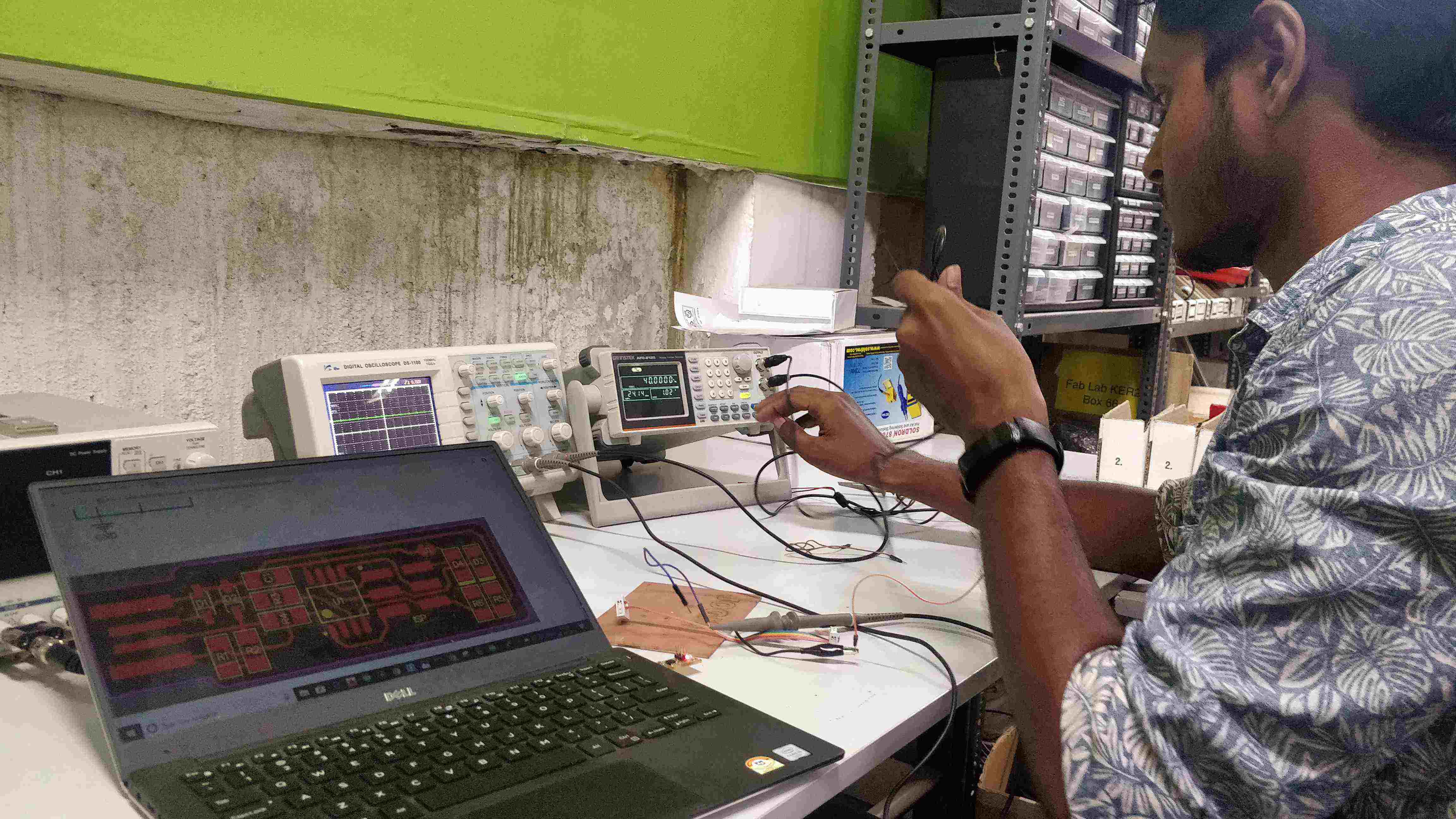
The group assignment was to test the equipments in fablab with the microcontroller get familiarised with them. I used the equipments and multimeters to test the errors occured in the echoboard i justmade for which i was not getting output initially
.
.
.
.
.
.
The group assignment was to test the equipments in fablab with the microcontroller
.
The GPD3303D is a 3-channel multiple output programmable linear DC Power Supply contain the superior technology and high quality which GW Instek had established through its long history of power supply design and manufacturing.
.
I chose digital storage oscilloscope to check the output of my pins ,since i was not getting output from the LED. following are the specificaions of the oscilloscope
.
The AFG-2100/2000 Series Arbitrary Function Generator is a DDS (Direct Digital Synthesized) based signal generato.It can generate output of Sine, Square (Pulse), Ramp (Triangle), Noise and Arbitrary waveforms. It provides 20M Sa/s sampling rate, 10 bit vertical resolution and 4k point memory .Also it can generate 0.1Hz resolution of Sine, Square and Triangle waveforms and the 1% ~ 99% adjustable duty cycle of Square (Pulse) waveform
The output of the function generator was connected to Oscilliscope