
Individual assignment: Measure something: add a sensor to a microcontroller board that you have designed and read it
Group assignment: Probe an input device's analog levels and digital signals
.
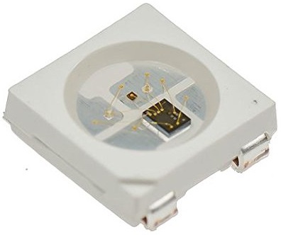
In the last week 10 for Moulding & Casting, i had made a batman made out of black panther and had temporarily added and programmed a neopixel LED as below
.
.
.
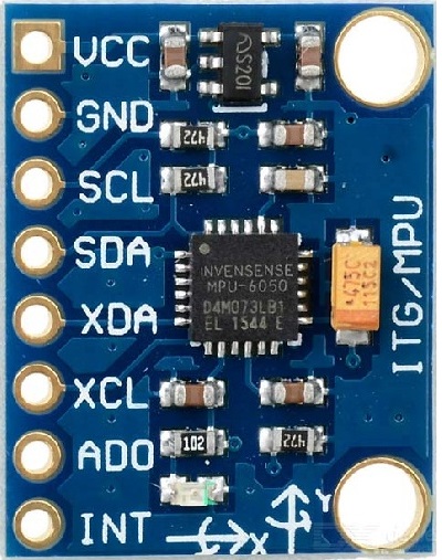
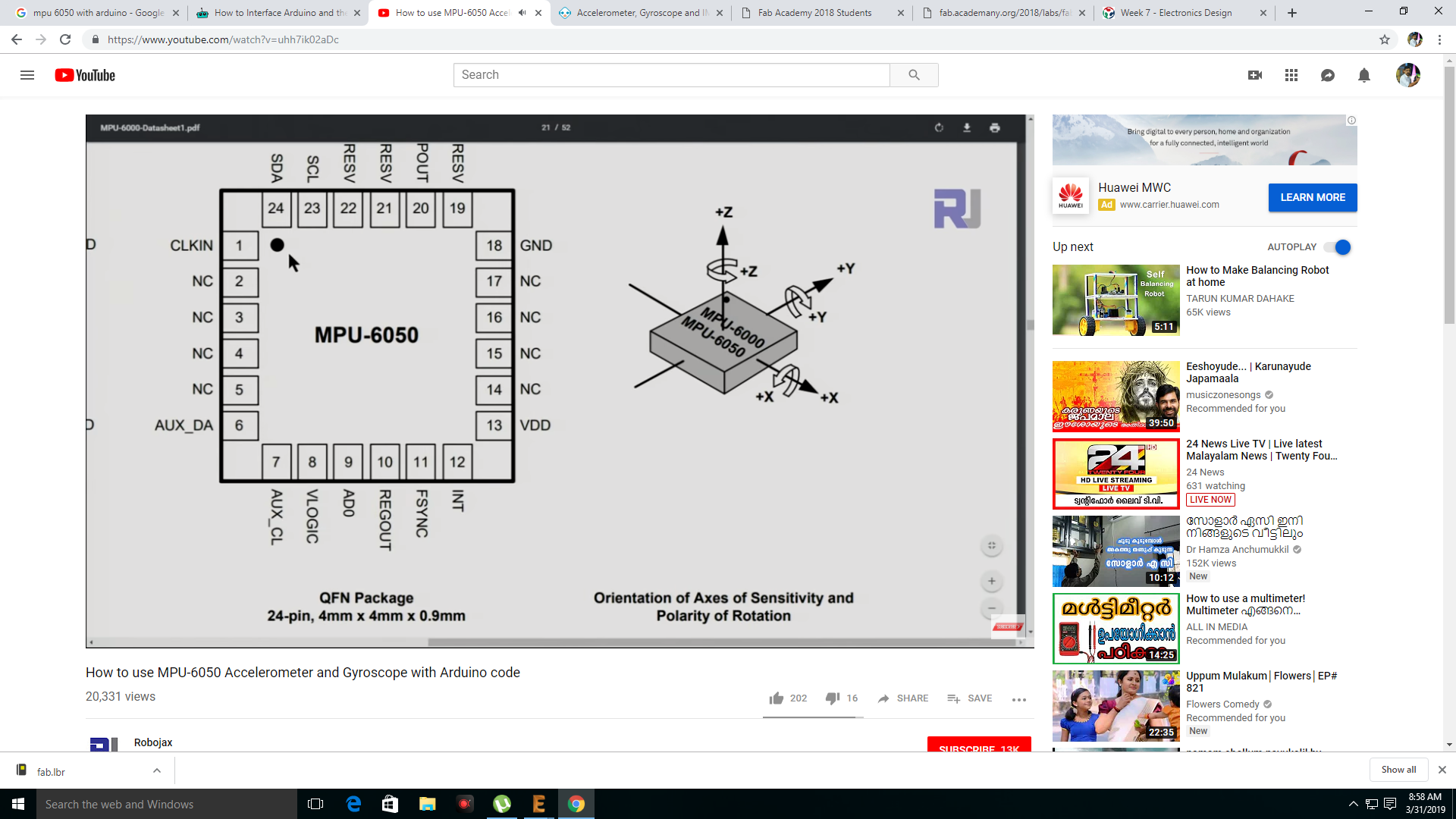
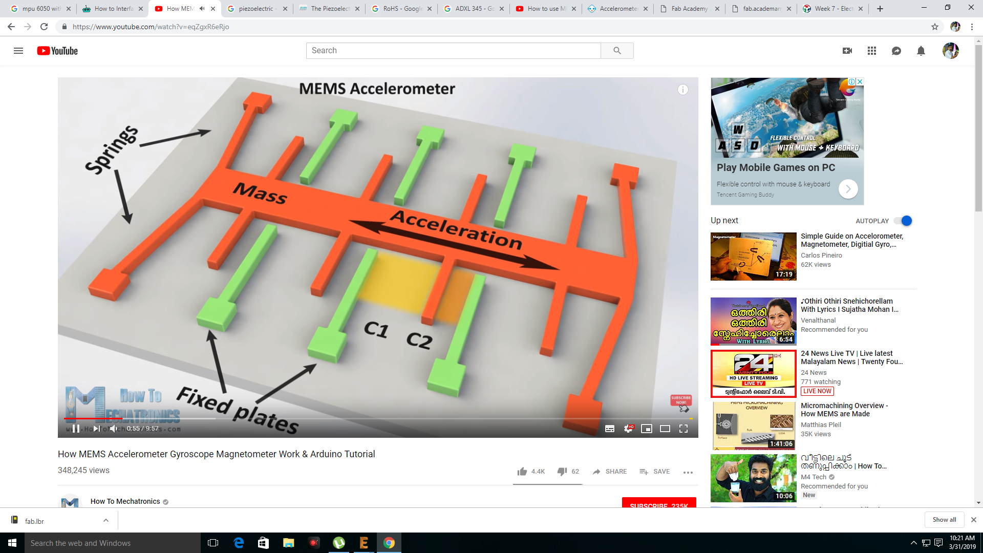
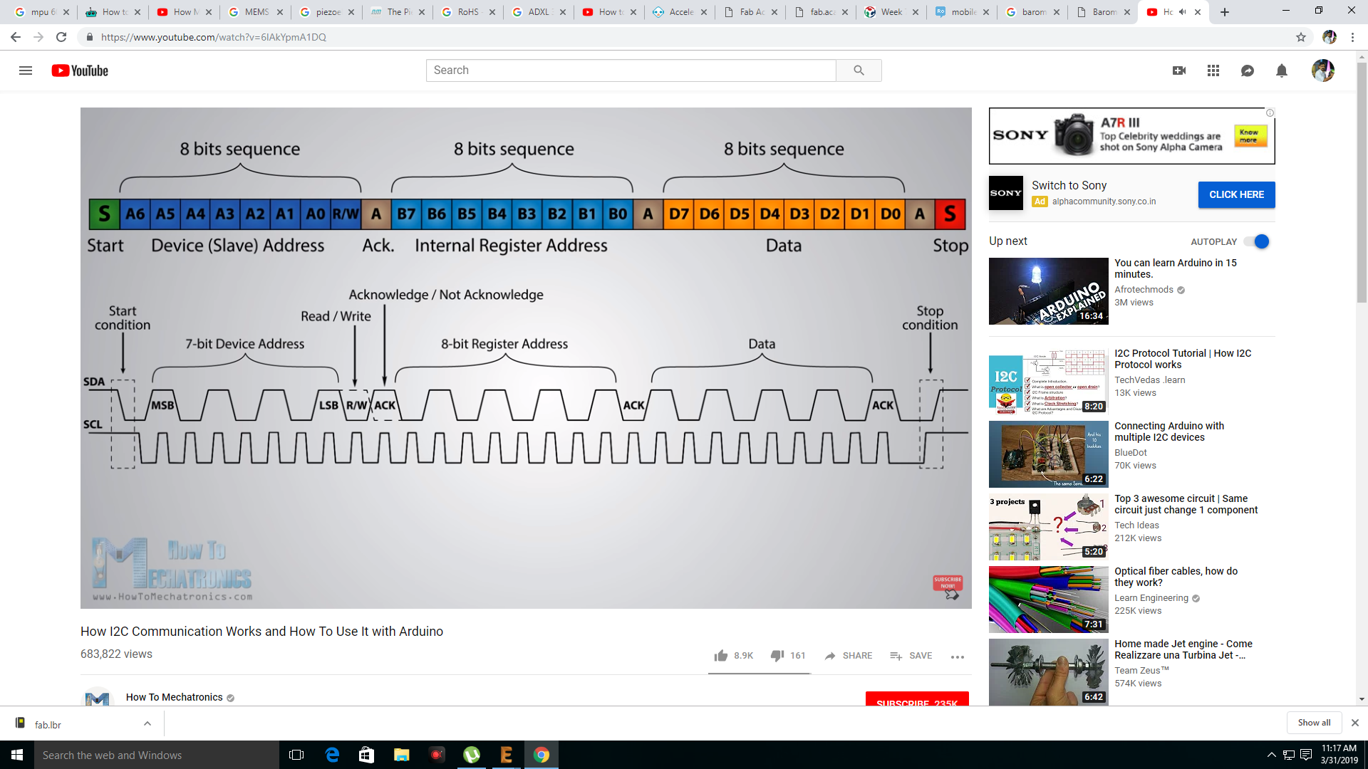
So this week i thought i would utilize the same with an input device. The first sensor that came to my mind was the accelerometer. So i thought of using MPU6050. I thought i could use the accelerometer in the module so that whenever i move the batman the rate of changeing of colour increases I went through several tutorials to study the working of the same. Since the MPU 6050 module used I2C communication, I found the below youtube links very useful for understanding the same
.
.
.
.
.
.
.
.
.
.
.
.
.
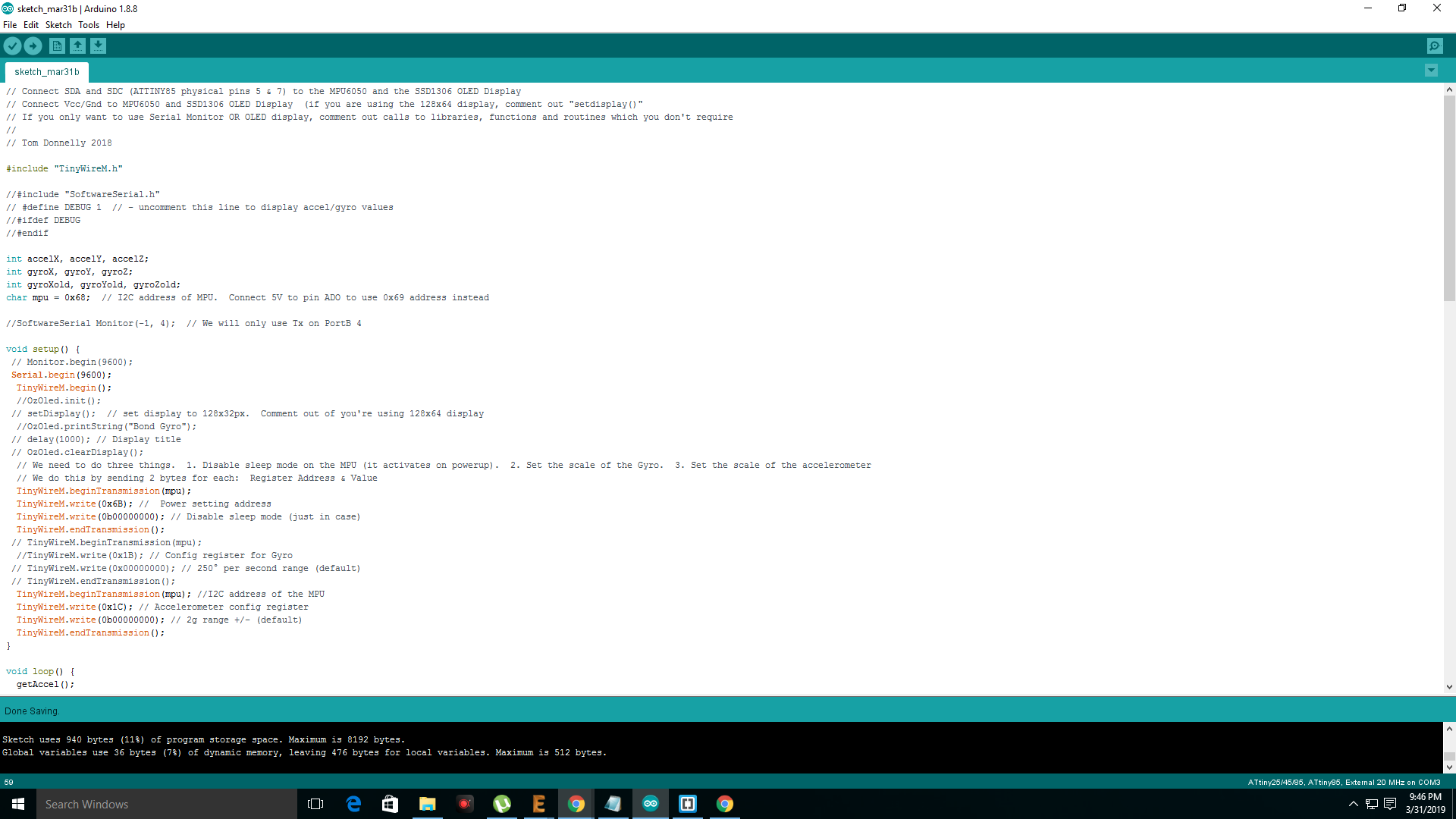
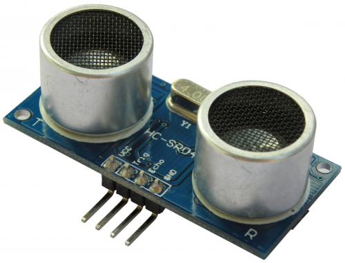
I thought i would use the same with attiny 44 and had found and modified the codes for the same. But i felt that there was a high chance of failure by using the same. Since i found only handful of supports for the interfacing with attiny 44 and mpu6050, i decided to test the working with another sensor before this. I desided to use the ultrasonics sensor module HC SR04 for the purpose of blinking the neopixel batman. If i get time then i will test the MPU6050 Sensor. My plan was to use this with neopixel LED WS2812B so that the colour changes instantly when the distance measured by the sensor is low
.
.
.
.
.
.
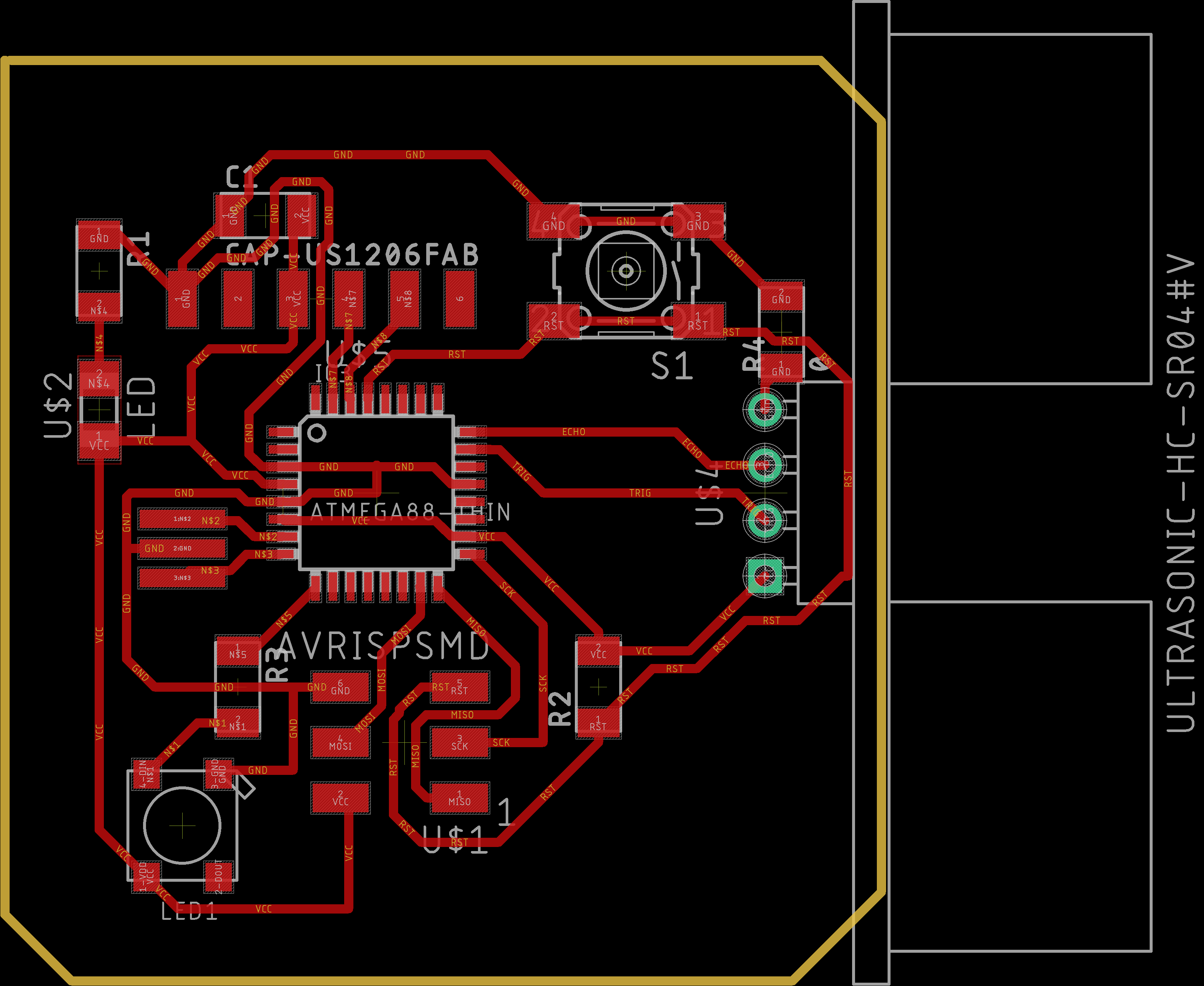
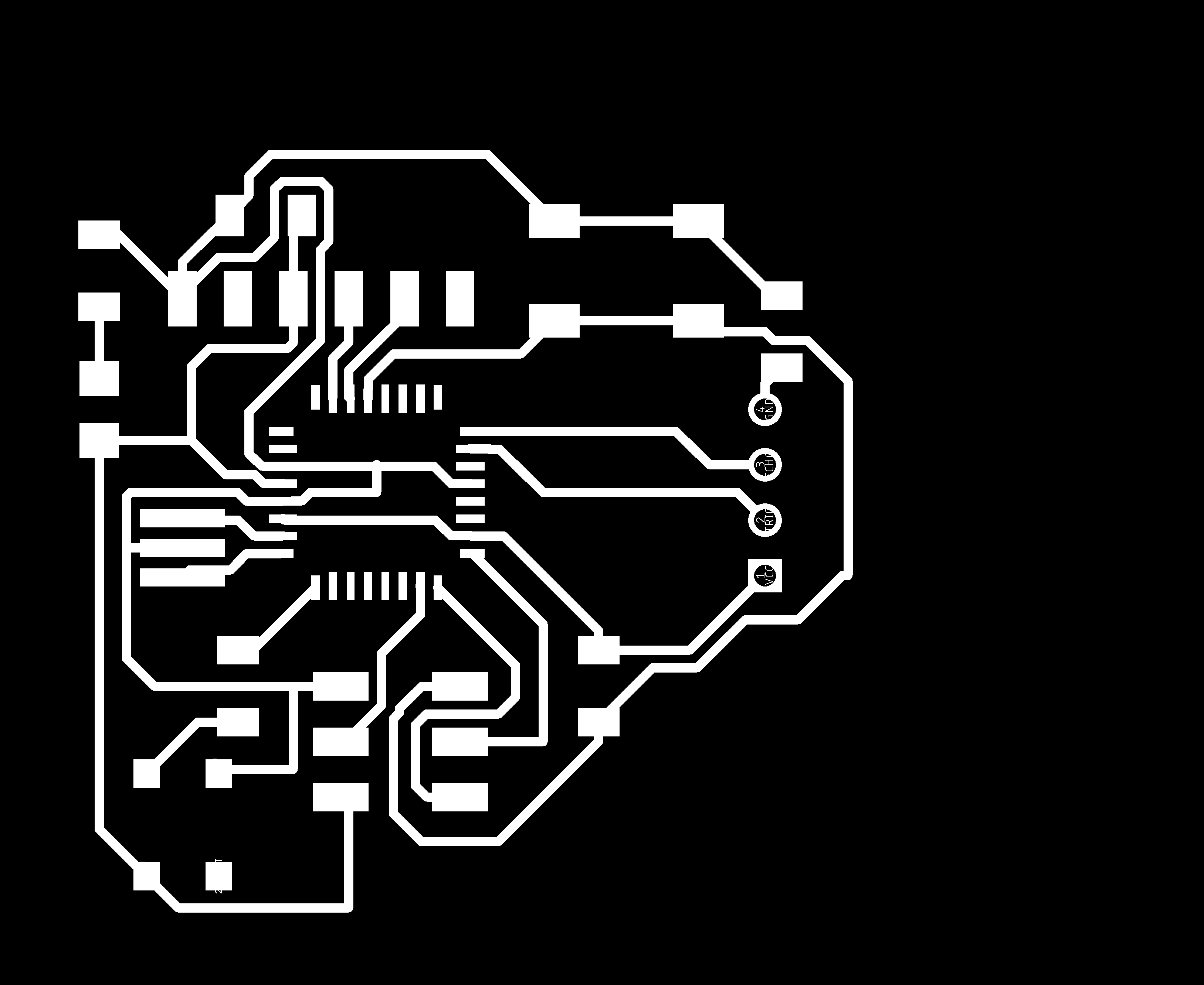
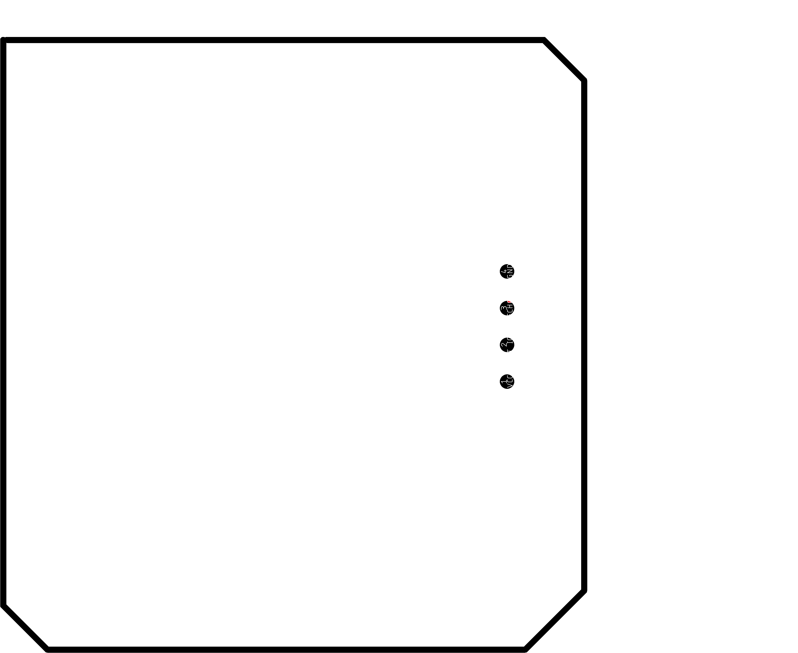
First we have to design the same in eagle by placing the required components and check whether the program and scheme would work
.
.PNG)
.
.
.PNG)
.
.
.PNG)
.
.
.PNG)
.
.
.
.
.
.
.
.
.png)
.
.
.png)
.
.
.png)
.
.
.jpeg)
.
.
.jpeg)
.
// NeoPixel Ring simple sketch (c) 2013 Shae Erisson
// released under the GPLv3 license to match the rest of the AdaFruit NeoPixel lib

// How many NeoPixels are attached to the Arduino?
#define NUMPIXELS 1

// When we setup the NeoPixel library, we tell it how many pixels, and which pin to use to send signals.
// Note that for older NeoPixel strips you might need to change the third parameter--see the strandtest
// example for more information on possible values.
Adafruit_NeoPixel pixels = Adafruit_NeoPixel(NUMPIXELS, PIN, NEO_GRB + NEO_KHZ800);

int delayval = 500; // delay for half a second

const int trigPin = A0;
const int echoPin = A1;


long duration;
int distance1,distance2,distance3;

void setup() {
  // This is for Trinket 5V 16MHz, you can remove these three lines if you are not using a Trinket
#if defined (__AVR_ATtiny85__)
  if (F_CPU == 16000000) clock_prescale_set(clock_div_1);
#endif
  // End of trinket special code

  pixels.begin(); // This initializes the NeoPixel library.

  pinMode(trigPin, OUTPUT); // Sets the trigPin as an Output
  pinMode(echoPin, INPUT); // Sets the echoPin as an Input
}

void loop() {

  digitalWrite(trigPin, LOW);
  delayMicroseconds(2);

  digitalWrite(trigPin, HIGH);
  delayMicroseconds(10);
  digitalWrite(trigPin, LOW);

  duration = pulseIn(echoPin, HIGH);

  distance1 = duration * 0.034 / 2;

  distance2 = (distance1/400)*255;
  distance3= distance2*3;

  // pixels.Color takes RGB values, from 0,0,0 up to 255,255,255
  pixels.setPixelColor(0, pixels.Color(distance1, distance2, 89)); // Moderately bright green color.

  pixels.show(); // This sends the updated pixel color to the hardware.

  delay(delayval); // Delay for a period of time (in milliseconds).

}
.
.
.
.jpeg)
.
.
.
.
.jpeg)
.
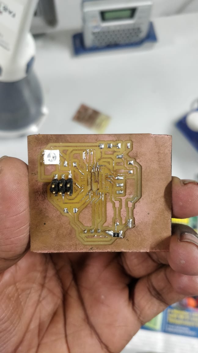
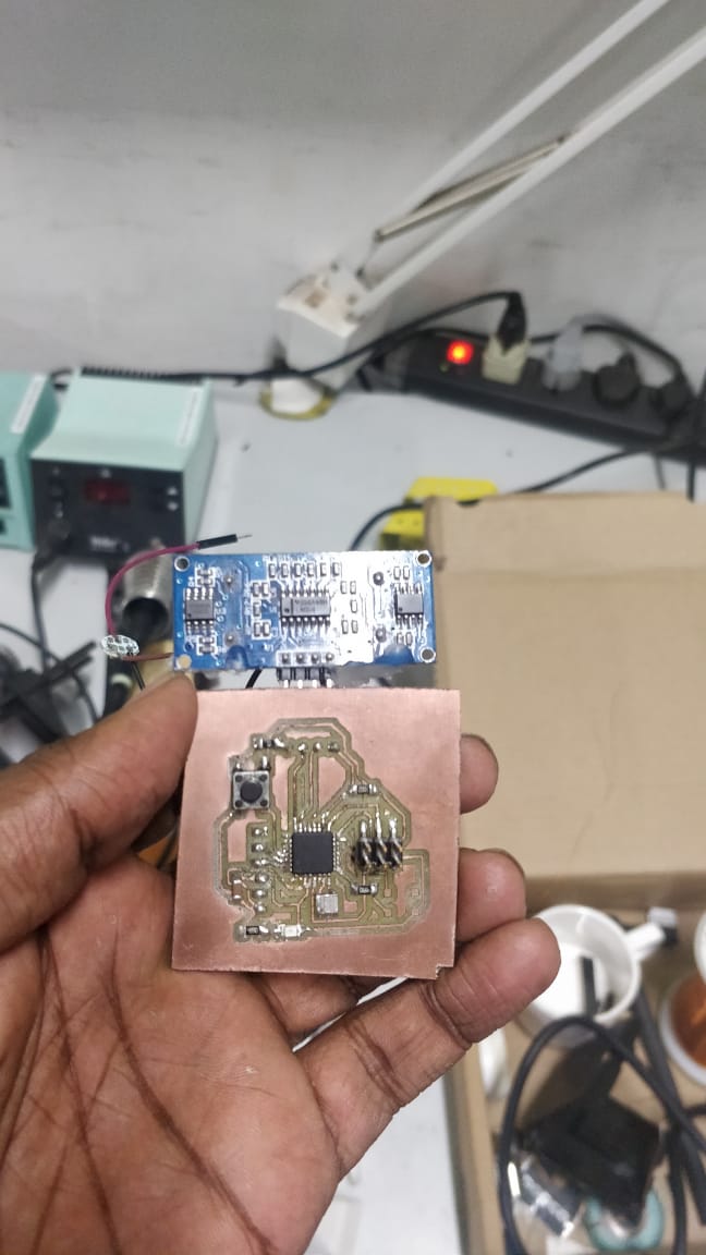
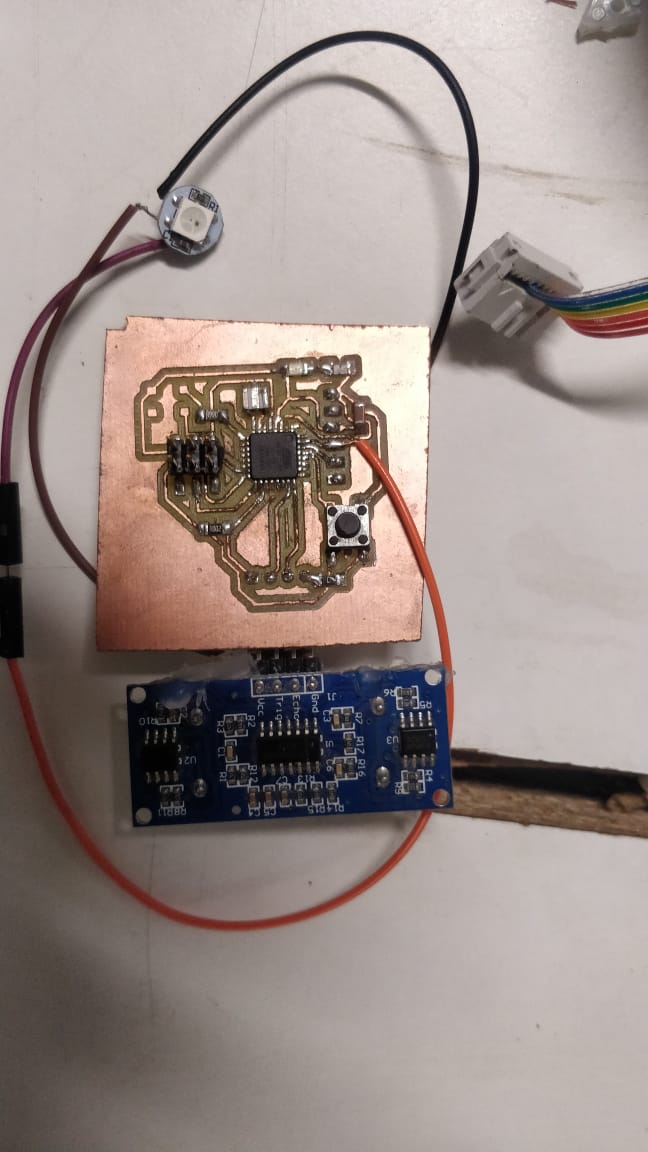
I made another board by using the working components from the other board and adding a new atmega328 IC .Since neopixel was in small quantity with me i seperately soldered an external NEOPIXEL using wires
.
.
.
.
.
.
.
.
.
.
.
.
.
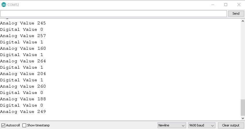
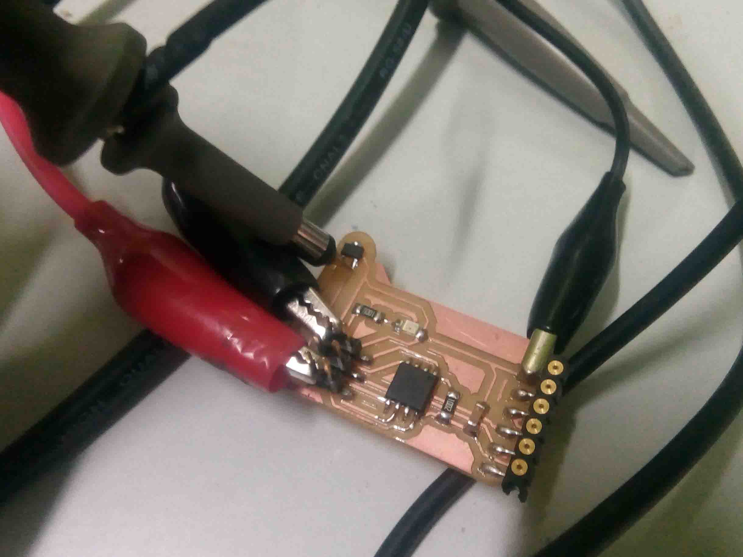
Probe an input device's analog levels and digital signals
The analog and digital values of the "Hall Effect Sensor" were measured. As per this code below
When a magnet is brought closer the analog value is changed as below
.
.
.
.