Week 8: Computer Controlled Machining
Group Assignment
Individual Assignment
Group Assignment
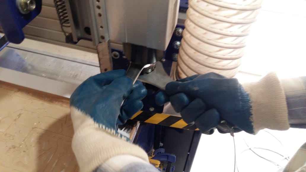
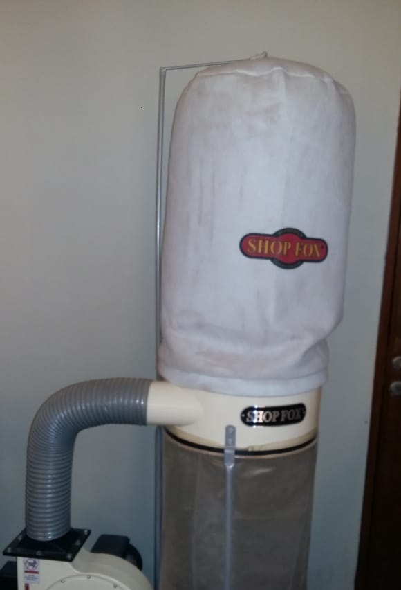
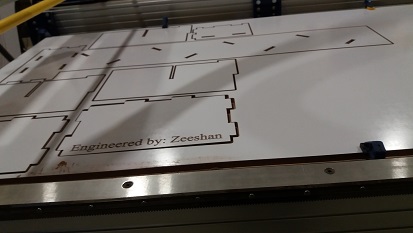
First and foremost we read this document where feeds, speeds and other stuff is explained very well after that we started with milling process so before starting with the milling process, the first thing that needs to be done is to install the desired milling bit, material and vacume chamber. The desired material can be placed and fixed tightly on the shopbot bedsheet. Placing the clamps is very crucial because if you placed them at wrong position then cnc machine might hit the clamps and ruins everything. Vacume chamber is also necessary which can be seen below in figure. This vacume is used to take off all the swarf outside of shopbot bedsheet and save in vacume chanmber. Furthermore it is very necessary that bit should be installed in the collet and this is done with the help of these special spanners. After doing this all we connect the system with the shopbot software installed using the 2 USB cables which are provided. On opening the software the axial location of the bit and a command like a screen appears.
Now we need to move the drill bit to a point that we consider origin. To do this open the keypad option by clicking the yellow icon in the position menu. By using the arrow key or the on-screen arrows move the bit to the desired origin point. Setting Z could be slightly tricky. The bit should touch the bed exactly at a point that it scraps the top layer.
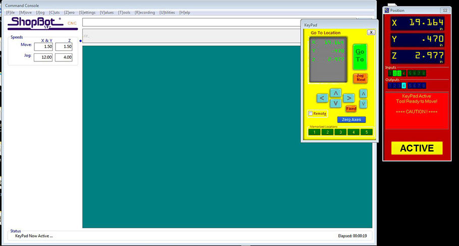
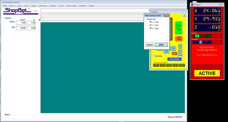
The bit can be moved slowly by clicking on the fixed button. Once the origin is set, click on zero axes and set x,y, and z as zero.
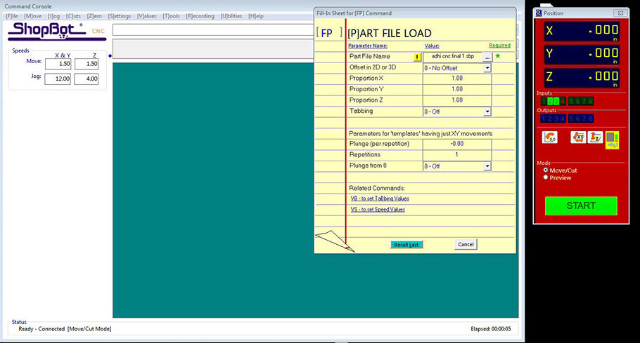
Now its time to import the G-code into the software and this can be done by clicking the cut parts and choosing the GCODE file. Hit start. The code gets loaded up and a message appears to hit the start button in the control box.
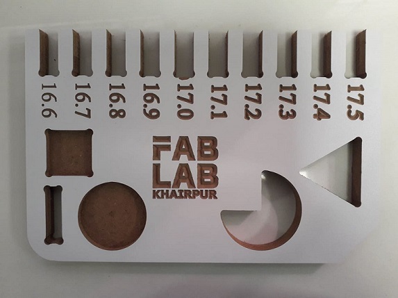
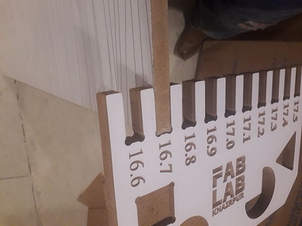
For group assignment we made a design in solid works and cut it in CNC machine. In this design we made some female-teeths of different sizes for the kerf testing, also made a cylider, a pocket, triangle and a rectangle as shown in the images. We have the MDF sheets in lab with thickness of 16.3mm. We used both outside cut and inside cut on different areas and also used pocket tool path which can be seen below and after cutting it was fixed in 16.7mm teeth.
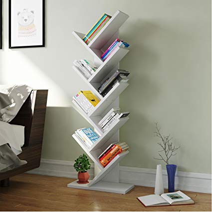
Initially I did my group assignment with the help of my instructors. Later I did individual assignment which was to make something big. In order to complete the assignment I tried to find the pressfit ideas on pinterest which I found few very useful like pressfit tables, stools and shelves. I decided to design a pressfit book shelf for that I found a sample idea from google.com. The major thing which I tried in this design is to make it pressfit. I did it using solidworks because it is good as compared to others.
Individual Assignment
This shelf is divided into five parts.
1. Back Bone
2.Base Element
3. Mid Element
4.Top Element.
5. Base
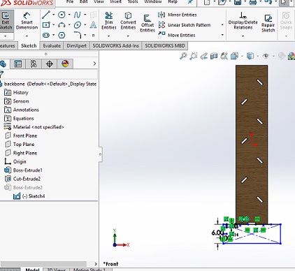
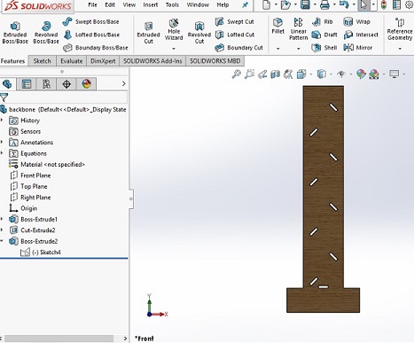
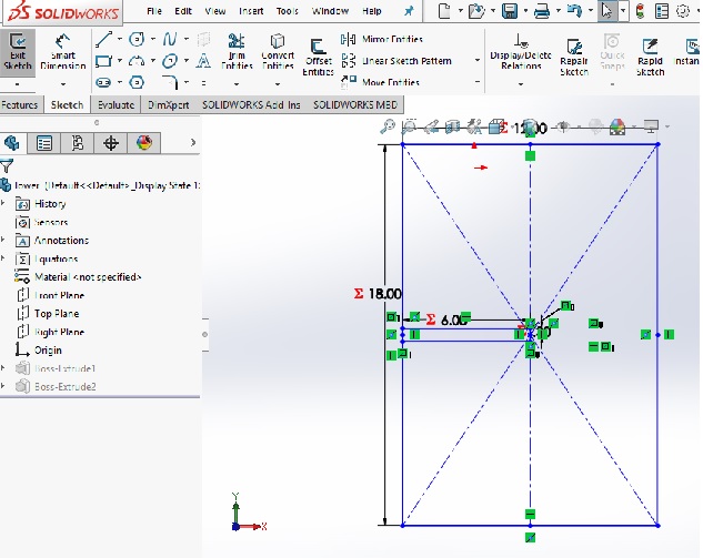
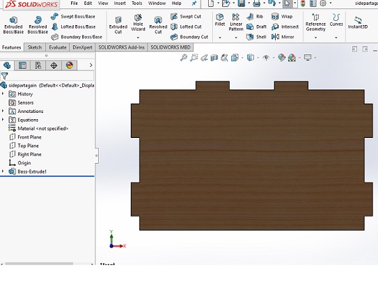
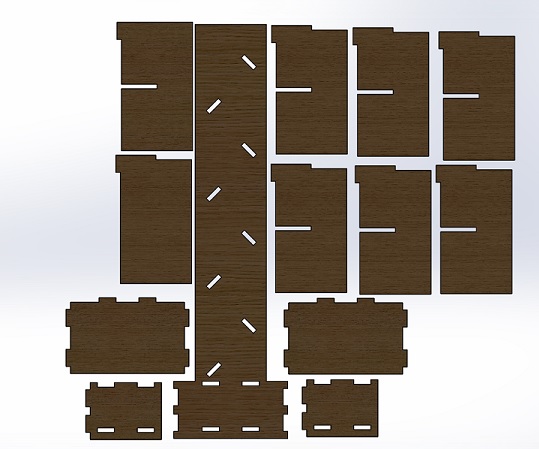
The primary step was to design it's back bone reck which shall hold all the elements. It was very critical for me to design that because I had to decide the number of teeth and their location. After thinking alot I decided to make a single teeth at each joint which can be seen below. There are almost eight holes in back bone because of 8 theeth will be inserted in this bone. The length and width of element was 52X10 inches however each hole has size of 2.4x0.62 iches which can be seen below.
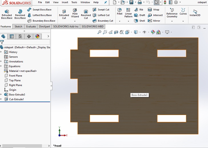
The secondary step is to design it's base element which I designed while considering the shelf structure. There was single teeth in this design however I had to make small cut which shall hold the other mid element of shelf. The length and width of base element was 18X10 inches however cut width and length is 6x0.62 inches which can be seen below. The teeth length is 2.4 inches however width is 0.62inches in each case.
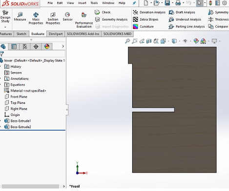
I did litle changing while designing the mid element. In order to join two mid element at right angle I made a small rectangular cut of length 6inches and width of 0.62 icnhes at upper edge and opposite of teeth.
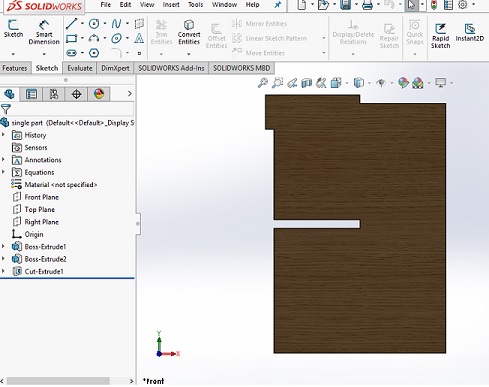
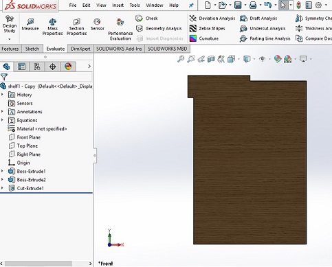
In order to design upper element I again did little change like I just removed the midle rectangular cut because there is no such usage of that cut at the end and it looks very odd. The solidworks sketch part and extruded part of upper element is shown below.
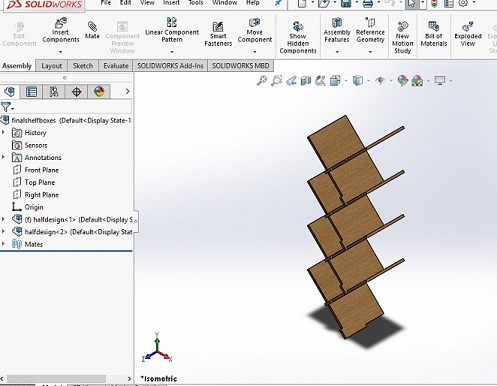
I assembled all parts in solidworks just to know any defect in design. And it happened I faced found few defects in making teeth in backbone there I changed the few angles and distances. The assembled part is shown below.
For cutting the designed parts I had to first check the sheet size later I needed to make dxf file of the designed shelf. so I started one by one and made a dxf file shown below
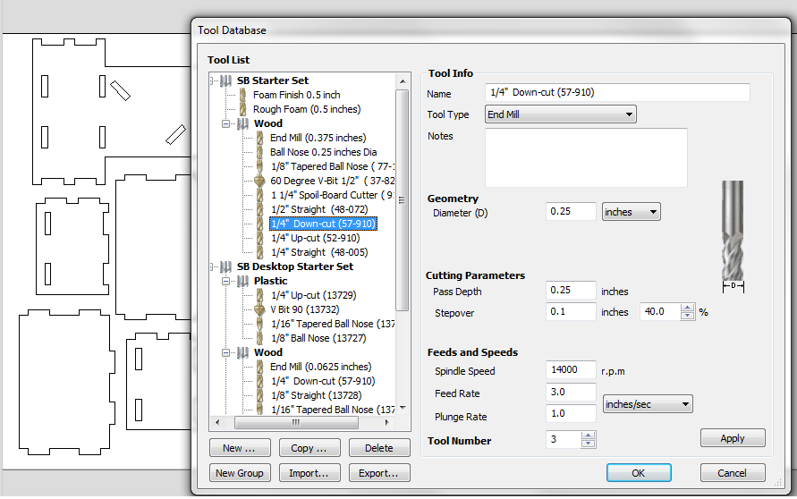
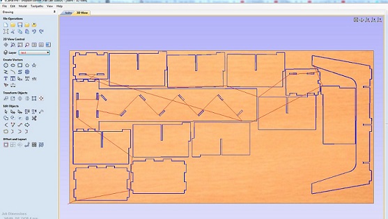
Vcarve software which is responsible for generating the toolpath as fab mods was responsible for pcb. The few things should be done before generating toolpath
1. Make dog bones because it will help to fit the teeth easly.
2. If you have a text make it to another layer.
3. Define number of pases that drill has to pass like in my case I used mdf card board of thickness 16mm so I used 5 number of passes. The drill cut a single part in five passes.
4. Define the outcut or incut.
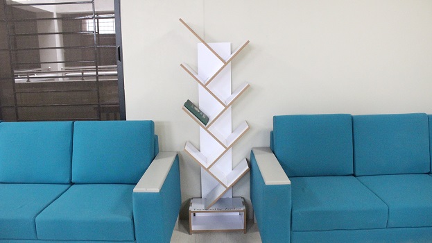
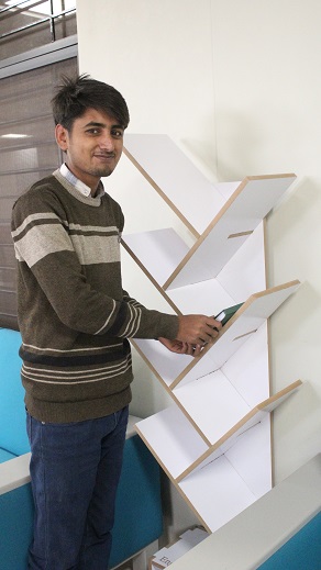
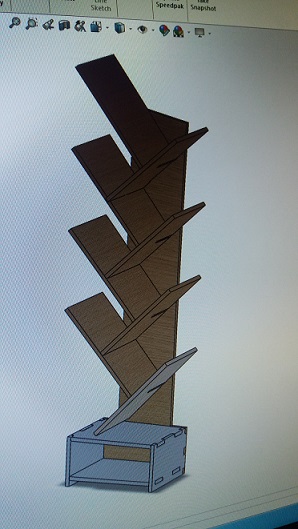
I assembled all parts with the help of my instructor Rasheed Ahmed Qazi. I placed this in between of two sofas of Fab Lab Khairpur. It looks really beutiful.