
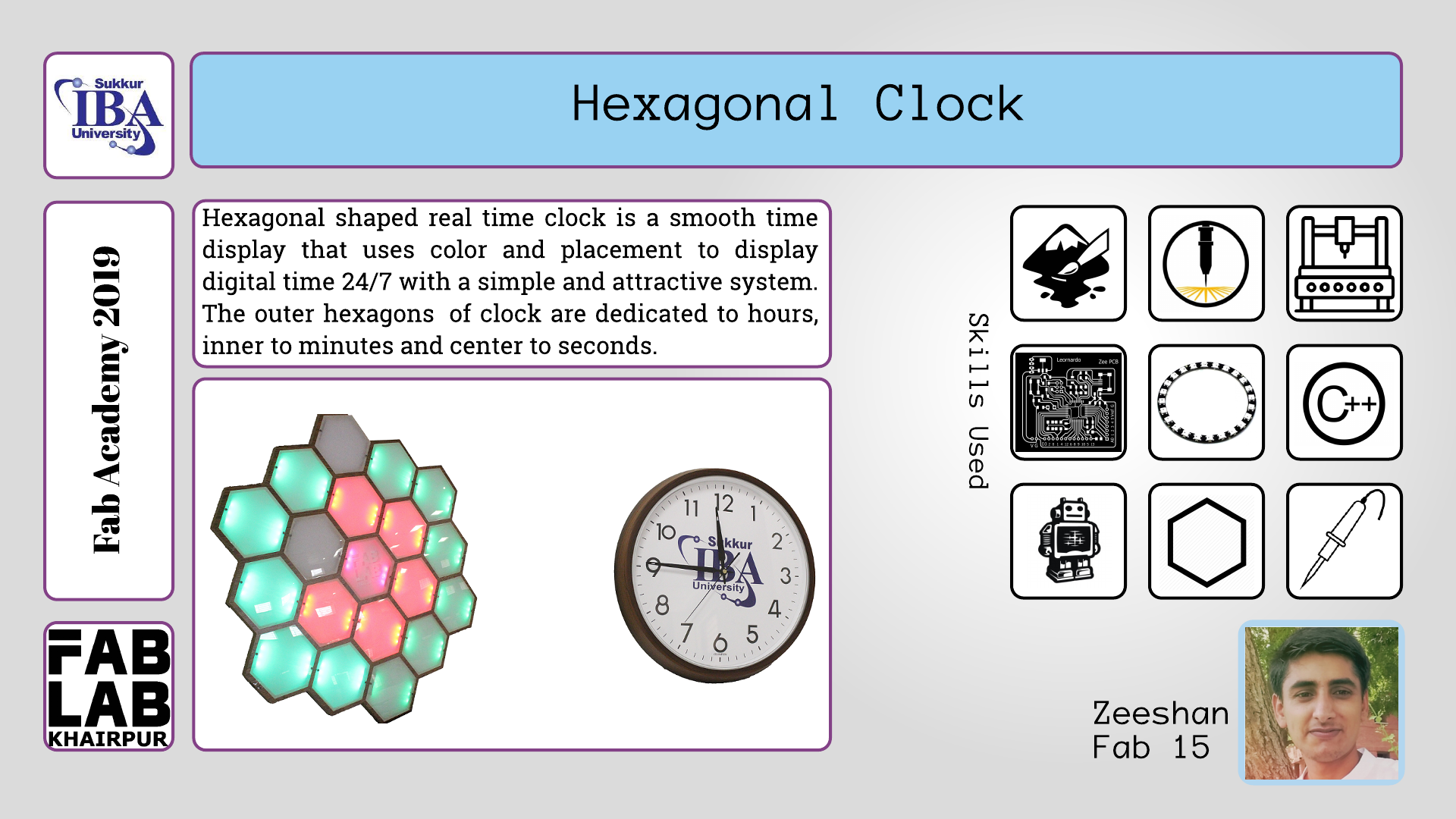
Final project is very essential part of fab diploma where candidate has to show mastery of skills learnt in almost every week. So for my final project I am making hexagonal shaped real time digital clock which shall display the time by lighting up the hexagones. In this clock I have ninteen hexagones which will be lighten up by addressable rgb leds. Among nineteen hexagones twelve will be dedicated to hours, six hexagones will be used for minutes and one remaining hexagone will be used for seconds. In order to make it happen I started with computer aided designing (cad) where I made it's hexagonal shaped design after that I used cnc milling where I cut this design which is covered in cnc milling section. Furthermore I used laser cutting for paper and acrylic sheet cut. I have pasted the laser cut paper in each hexagone. By using electronics and PCB skill I designed arduino leonardo and real time clock board which is also discussed below. I used arduino IDE for programming the both designed boards i-e arduino leoanardo and real time clock board. At the end I have 3d printed the casing for keeping the pcb boards inside. My final project is covered in following sections.
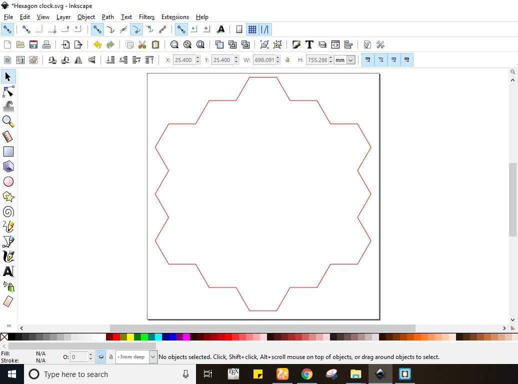
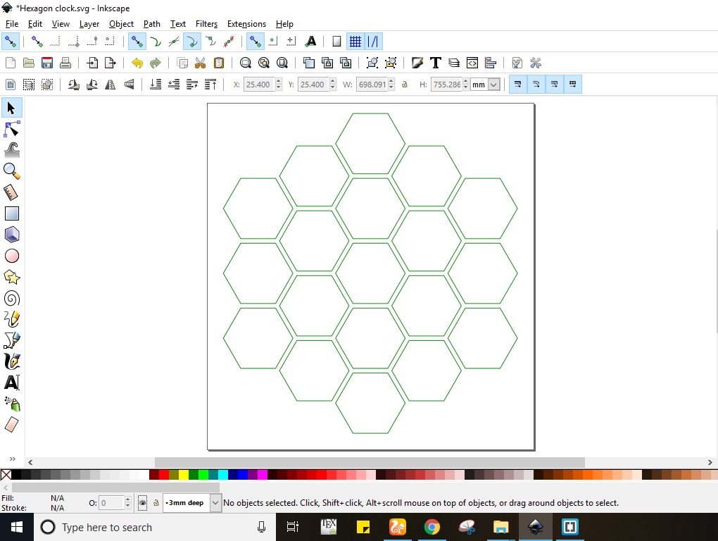
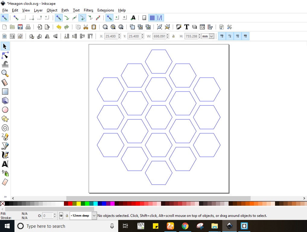
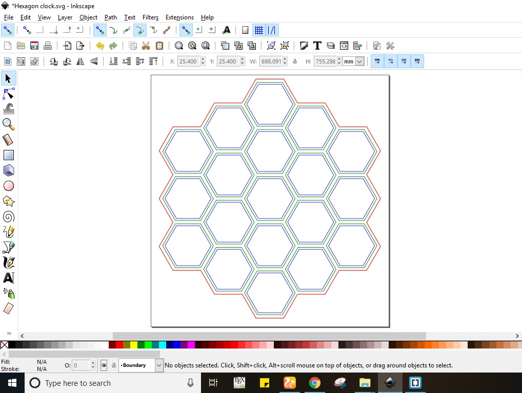
At the very first I made 2d computer aided design (cad) of proposed project in inkscape software. The design includes 3 vector cuts separately made in layers for example outcut , inner cut and deep cut. The outcut is boundary of designed clock, inner cut is 3mm deep which shall be used to place the acrylic hexagones and the deep cut is 12mm which shall be used to place the six ws128b type addressable rgb leds. The size of boundary hexagones is 3.425 inch per side while the angle is set to 60 degrees. Similarly the size of 3mm deep cut hexagone is 3.139 inch and the size of 12 mm deep hexagone is 2.85inch. The boundary, outcut, and inner cut are shown below in figure (a), (b), (c) respectively however the boundary, outcut and inner cut altogether are shown in figure (d).
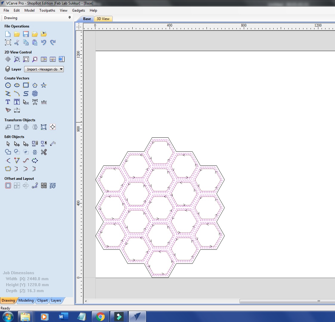
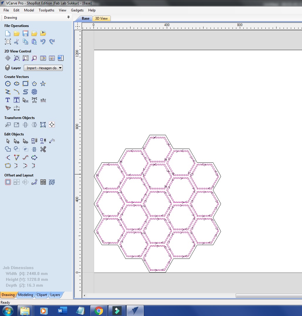
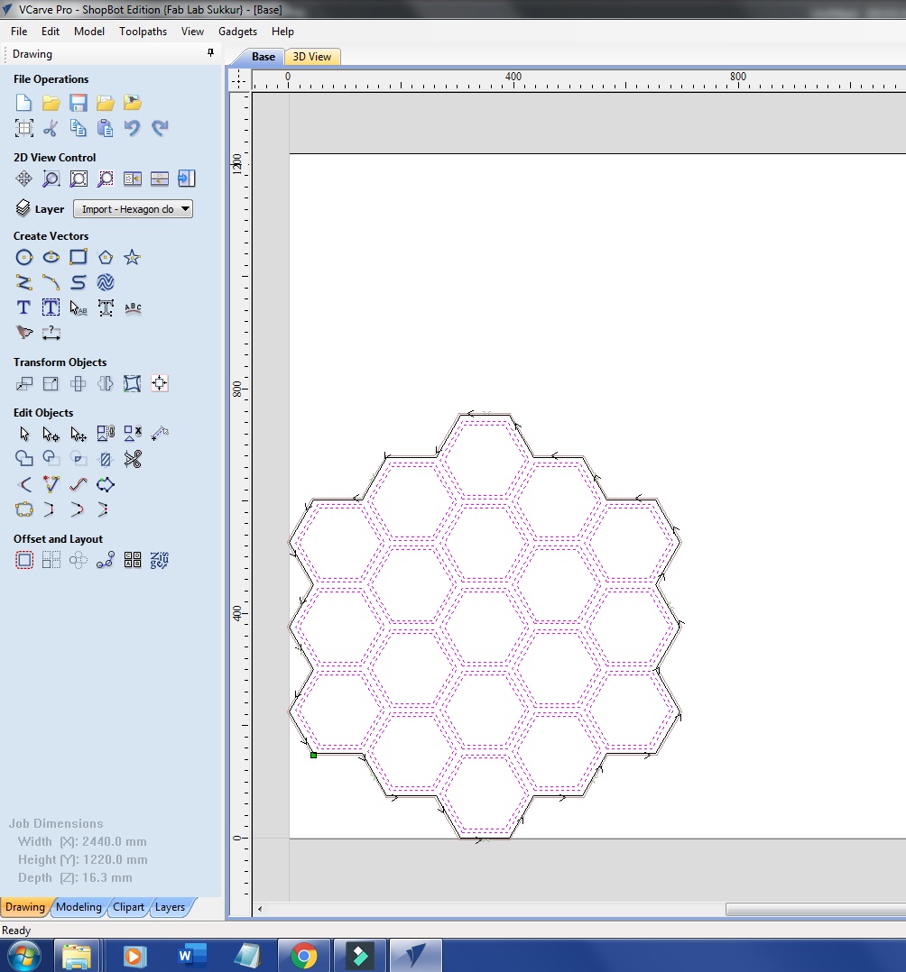
For cnc milling I need toolpaths so I exported the dxf file made in inkscape software to vcarve software which are used for toolpath generation. In this stage I have generated four toolpaths which are shown below in figures one by one. Figure (a) shows the pocket toolpaths which are made for 3mm deepcut, while figure (b) and (c) shows small pocket toolpath and it's clearance which is for 12 mm deepcut and figure (d) shows boundary toolpath. At the end there is video which shows the total preview of toolpath generation from pockets to boundary.
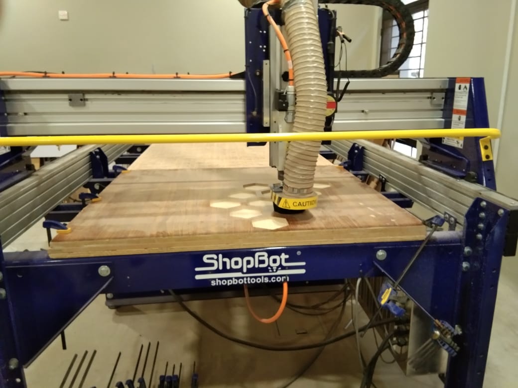
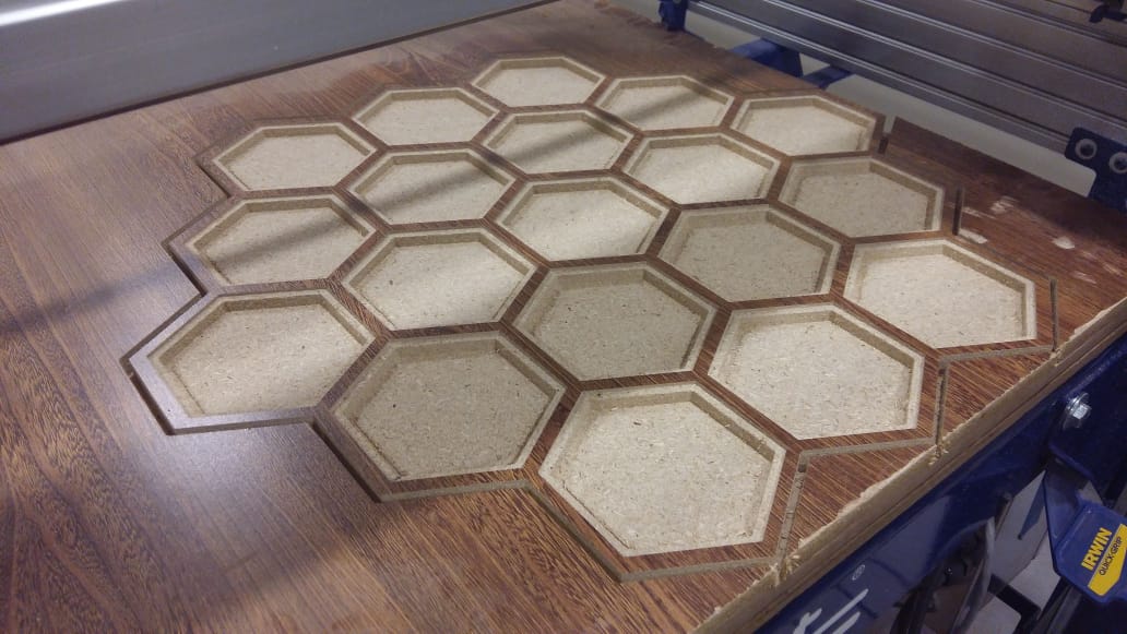
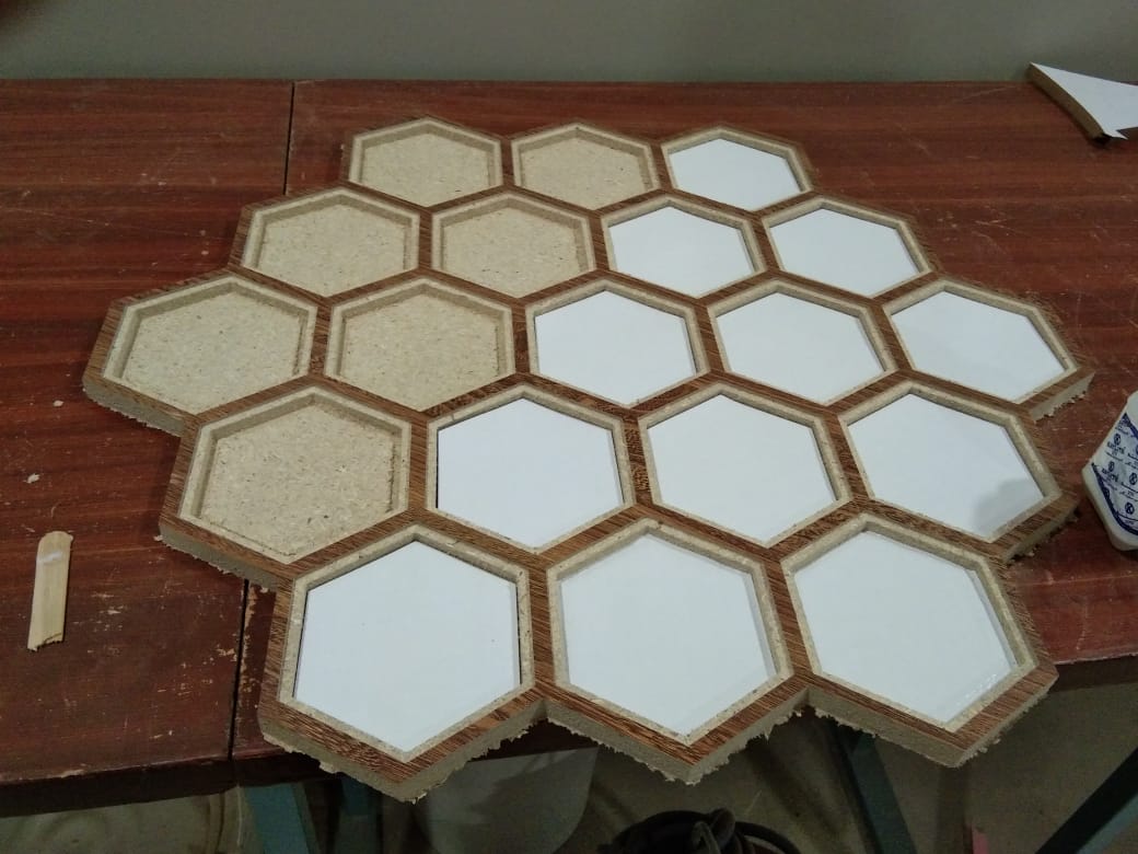
Next I cut the generated files in shopbot which can be seen below in figure. First I placed the mdf board properly on shopbot and changed the particular bit. I used different types of bits in this design for example I used half inch bit for pockets, small pockets and quarter inch for boundary. The figure (a) shows the shopbot machine while in milling mode and figure (b) shows final cnc milled output of design.
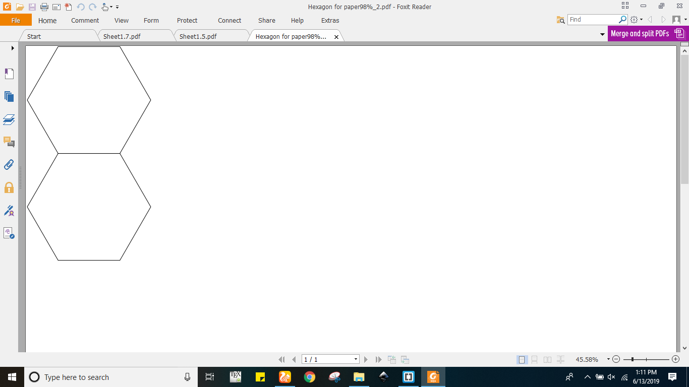
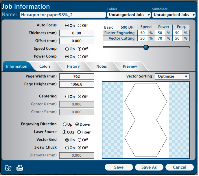
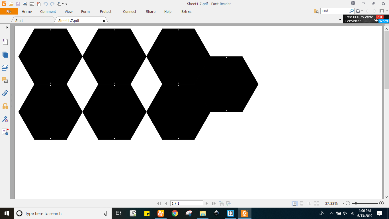
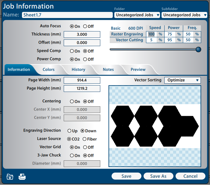
In this laser cutting section I had to make paper hexagones, and acrylic hexagones. Initially I made paper hexagones in inkscape software with size 98% of orignal hexagones. I reduced the 2% size in order to fit hexagones inside the mdf design. The figure (a) shows the paper hexagone in pdf form however figure (b) shows the paper hexagone job in epilog laser cutting machine where it can be seen that paper thickness is 0.100 mm however vector speed is 50% and power is 70%. Furthermore I have added the video which shows the paper cutting of hexagone in epilog laser machine. At the end I have pasted all the laser cut hexagones inside the mdf hexagones.
I did same for acrylic hexagones like I processed in ikscape and exported that file in pdf form can be seen below in figure (a). This figure shows that there are seven hexagones connected back to back. Further this figure also shows that there are circular cuts in every hexagone so these circular cuts in hexagones are used for screws which are used for fitting the acrylics over the body. The figure (b) shows the epilog laser machine job where it can be seen that material thickness is 3mm while raster speed is 100% and power is 75%. In order to get the diffusion I used rastering method which worked fine at above mentioned values however I used many other methods as well which did not worked for me like I used tissue paper, white spray, vinyl cutting and few difussion papers.
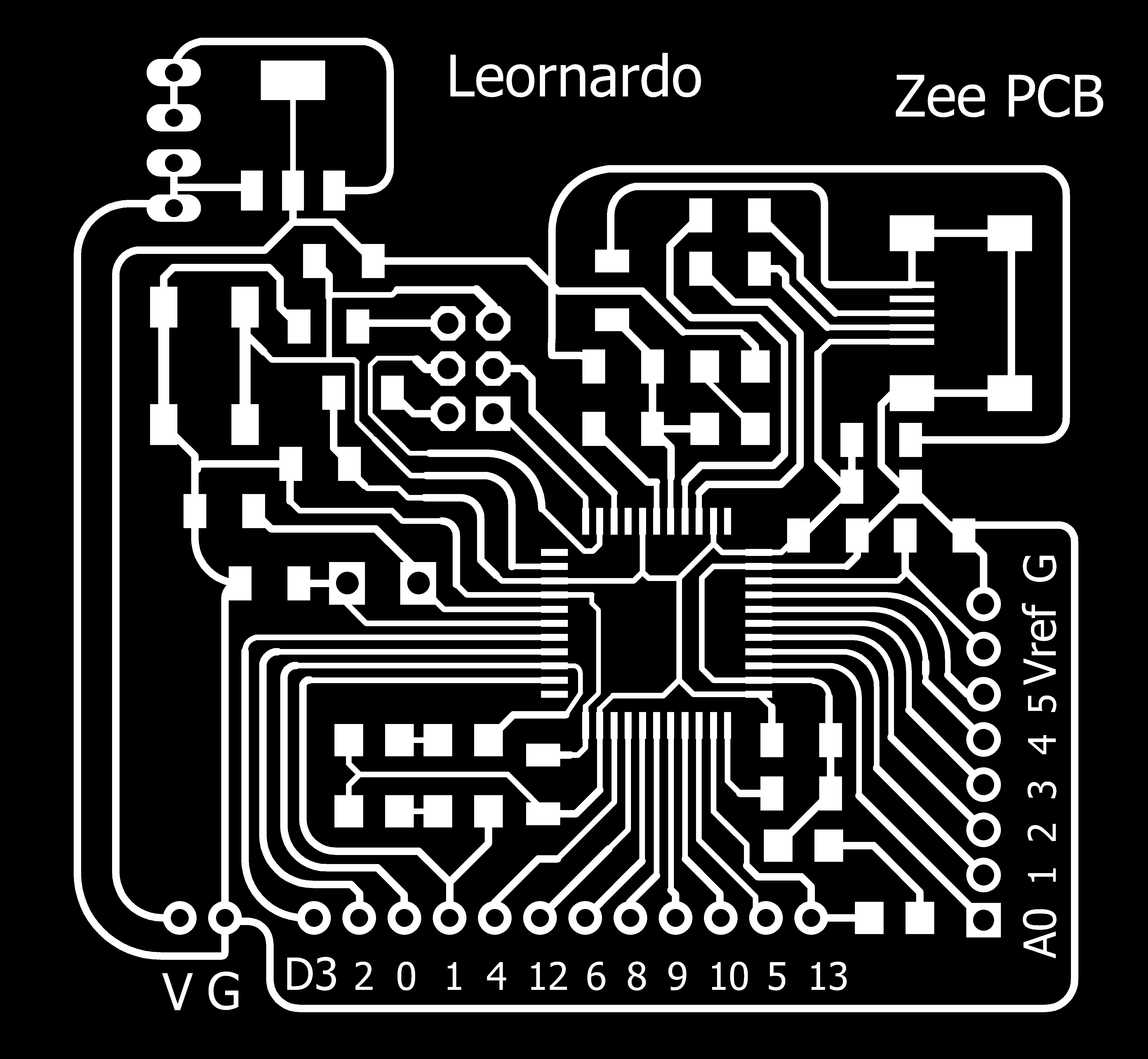
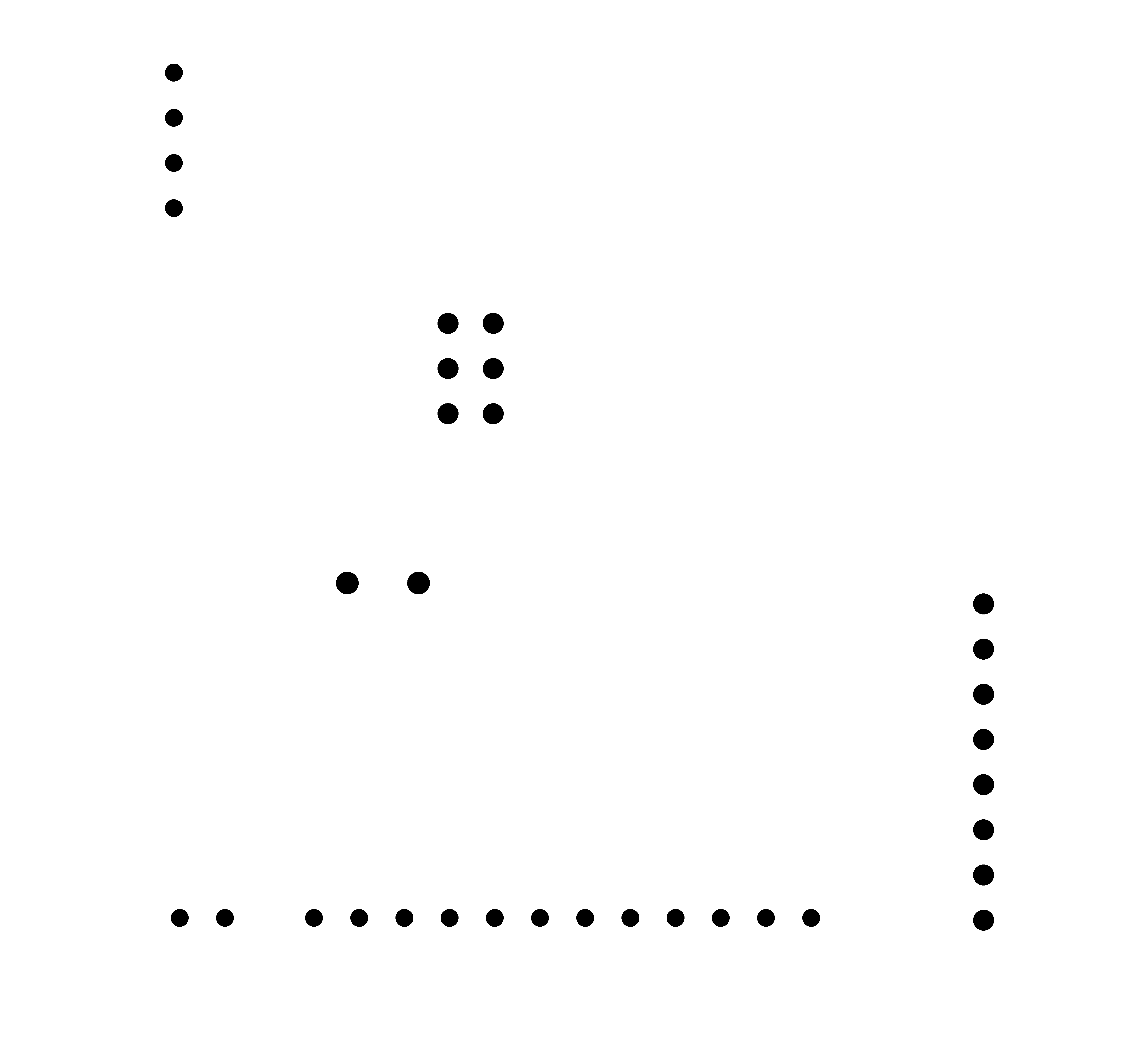
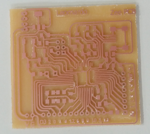
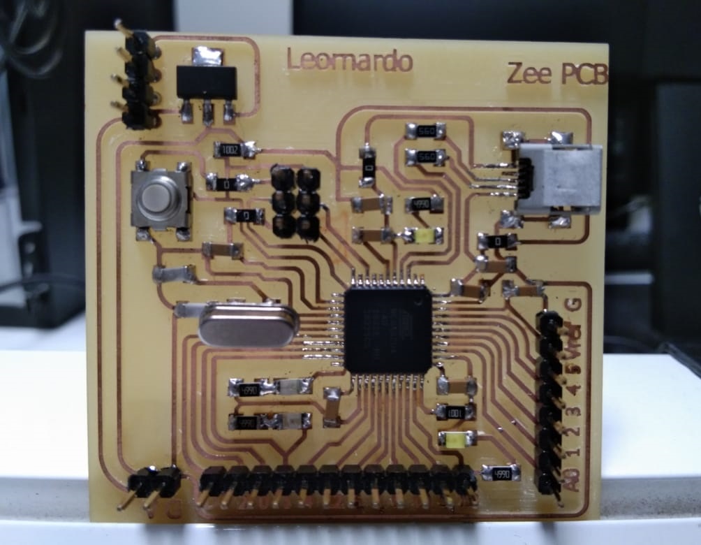
In order to make it functional I needed electronics for that I have already designed controller pcb in my week 11 input assignment. This leonardo controller pcb is a generic kind of controller which uses atmega328 u chip. Furthermore I also needed real time clock controller for clock programming. Figure (a) shows the schematic of atmega 328u microcontroller made in eagle software while figure (b) shows the monochrome image of designed board. Additionally figure(c) and (d) shows the drills and outline of designed board. In last figure(e) shows the printed circuit board (pcb) populated with smd components.
.png)
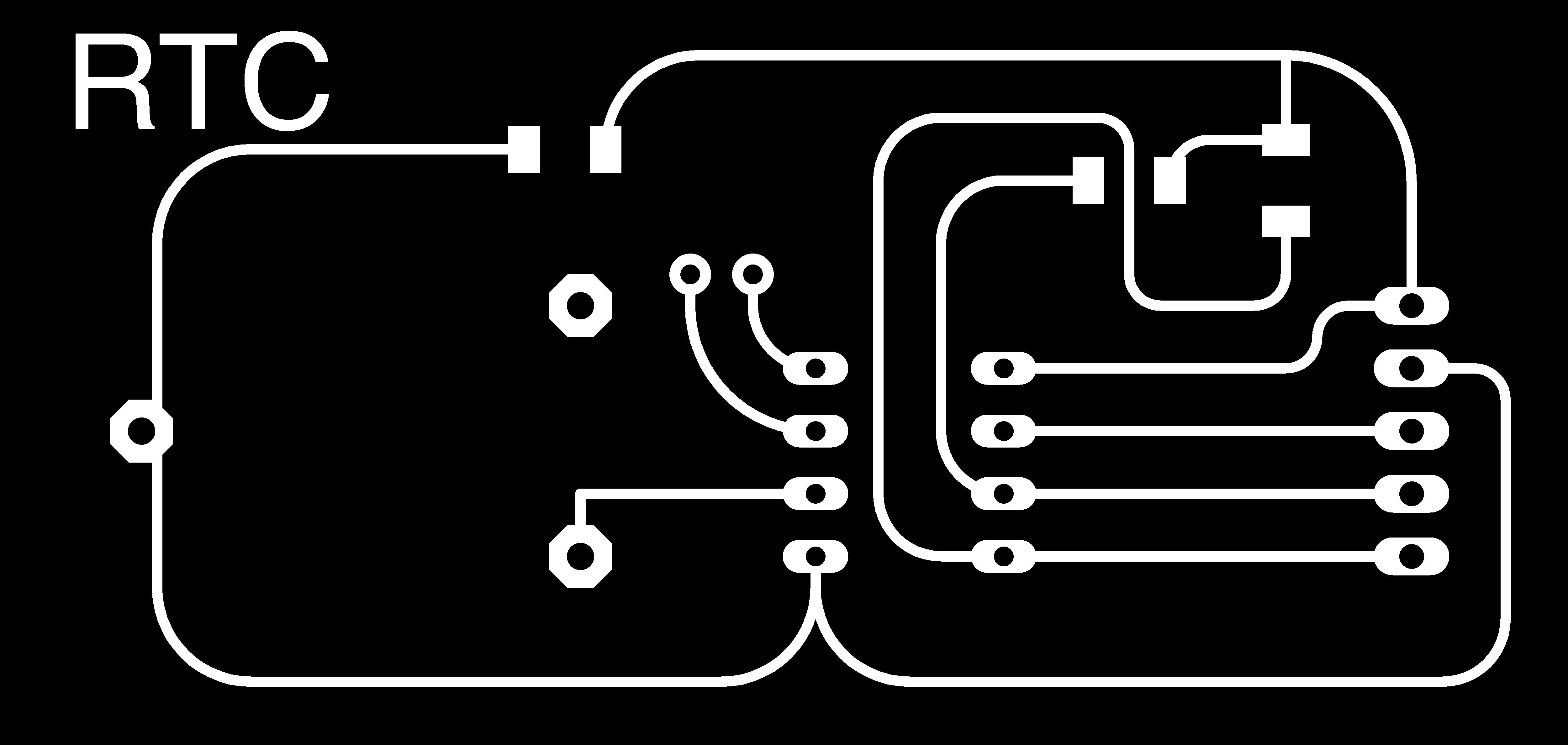
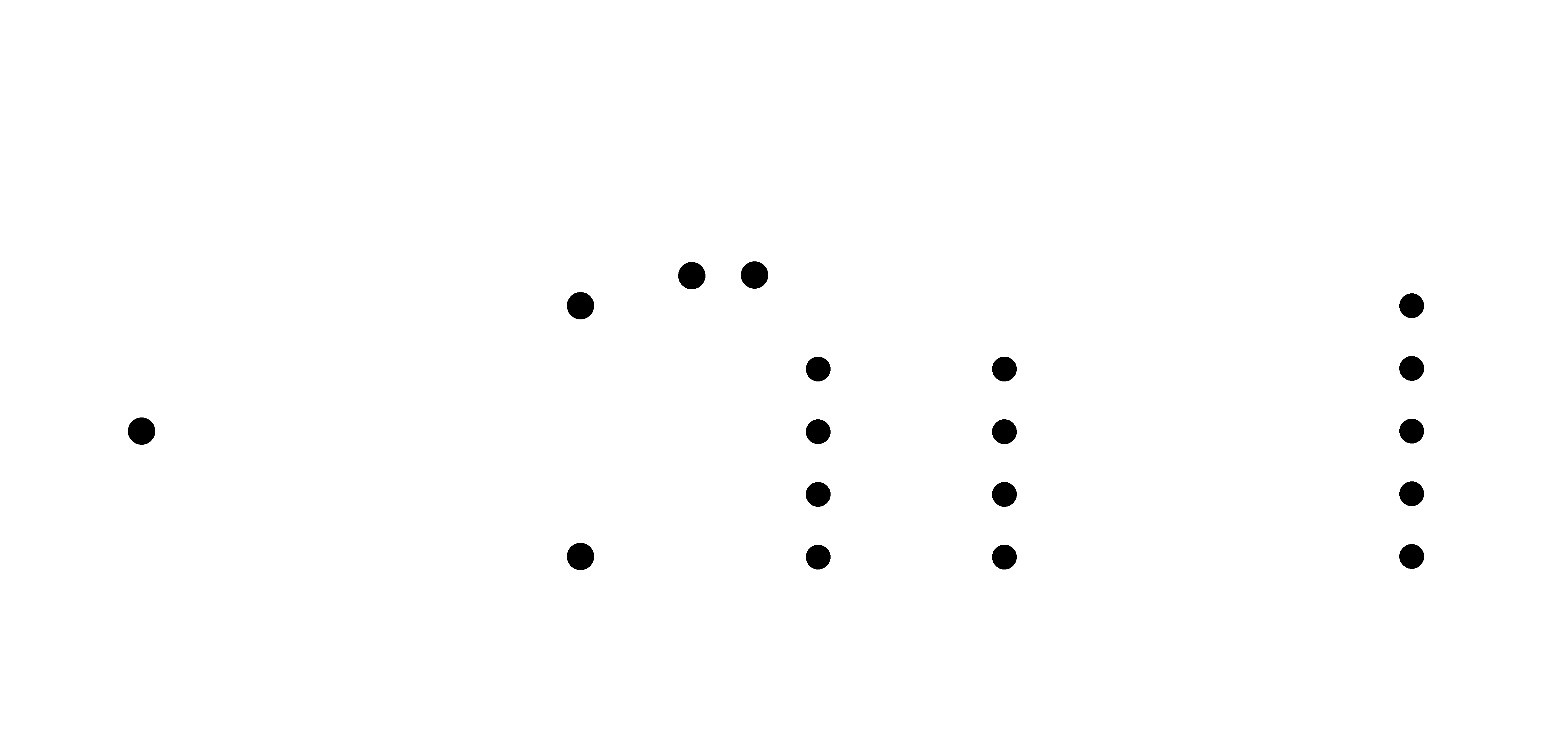
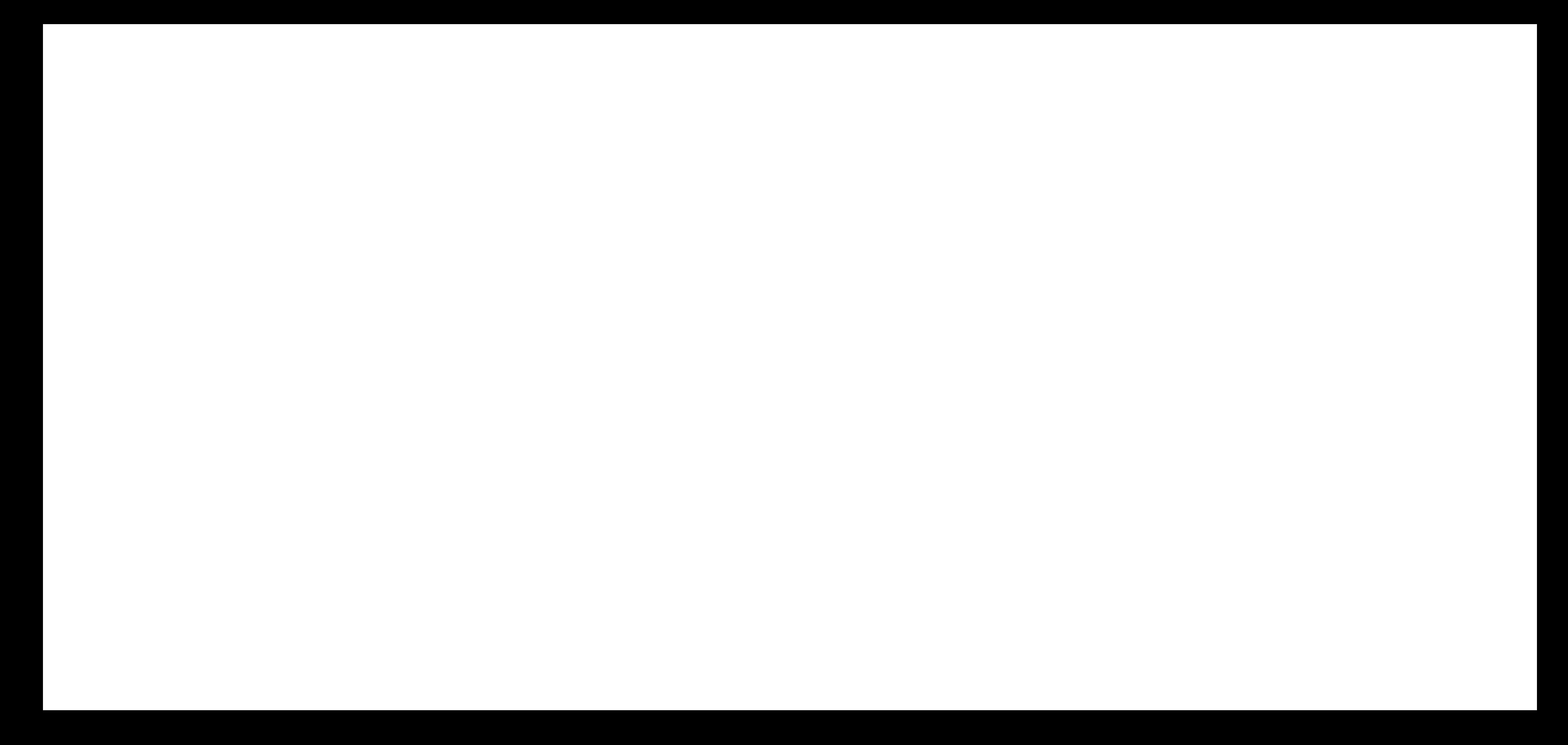
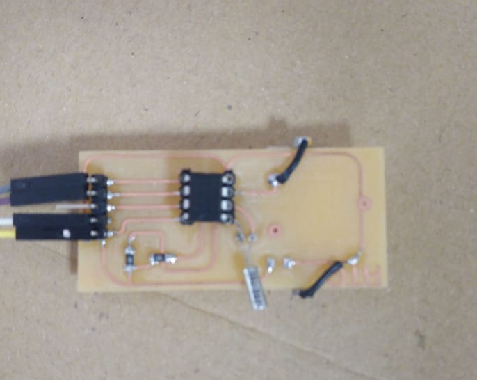
Similarly I made real time clock (rtc) board in eagle software which I have explained step by step. Figure (a) shows the eagle image snapshot where I have designed this board while figure (b) shows the schematics of designed real time clock. In order to proceed for pcb milling I needed monochrome image which are shown below for example figure(c) shows rtc trace, figure(d) shows the rtc drills and figure(e) shows the rtc outline of real time clock(rtc). In last figure(e) shows the rtc pcb after soldering.
.png)
.png)
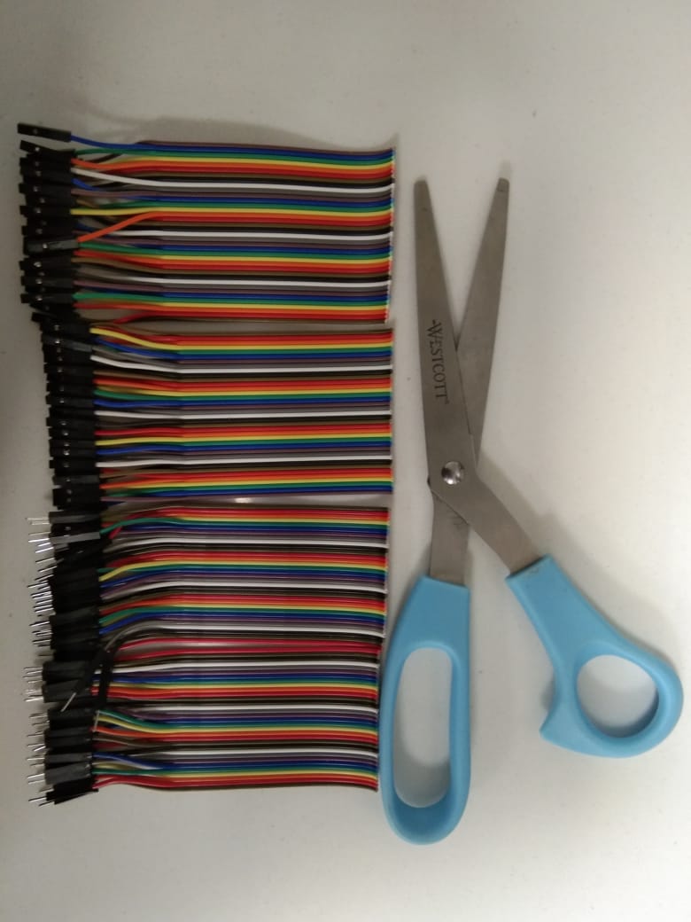
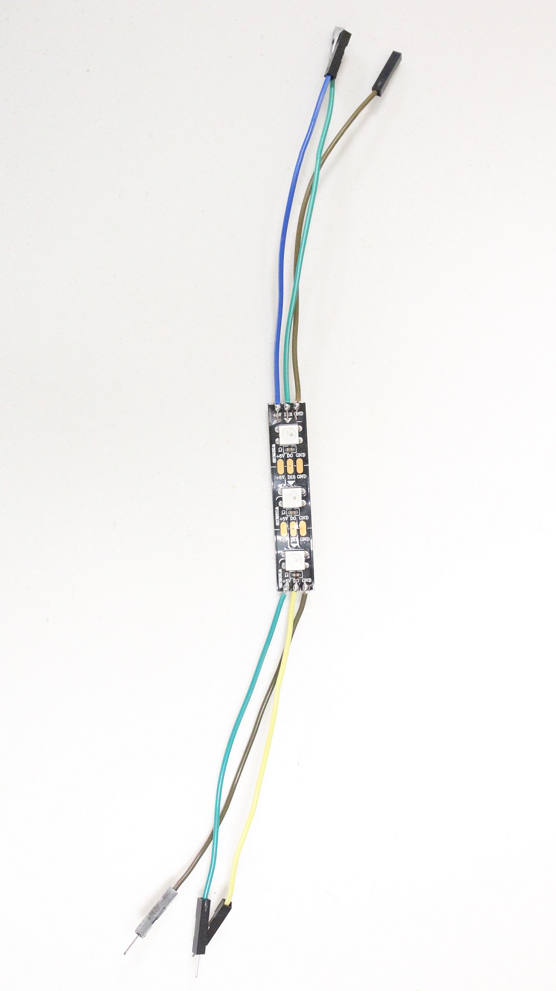
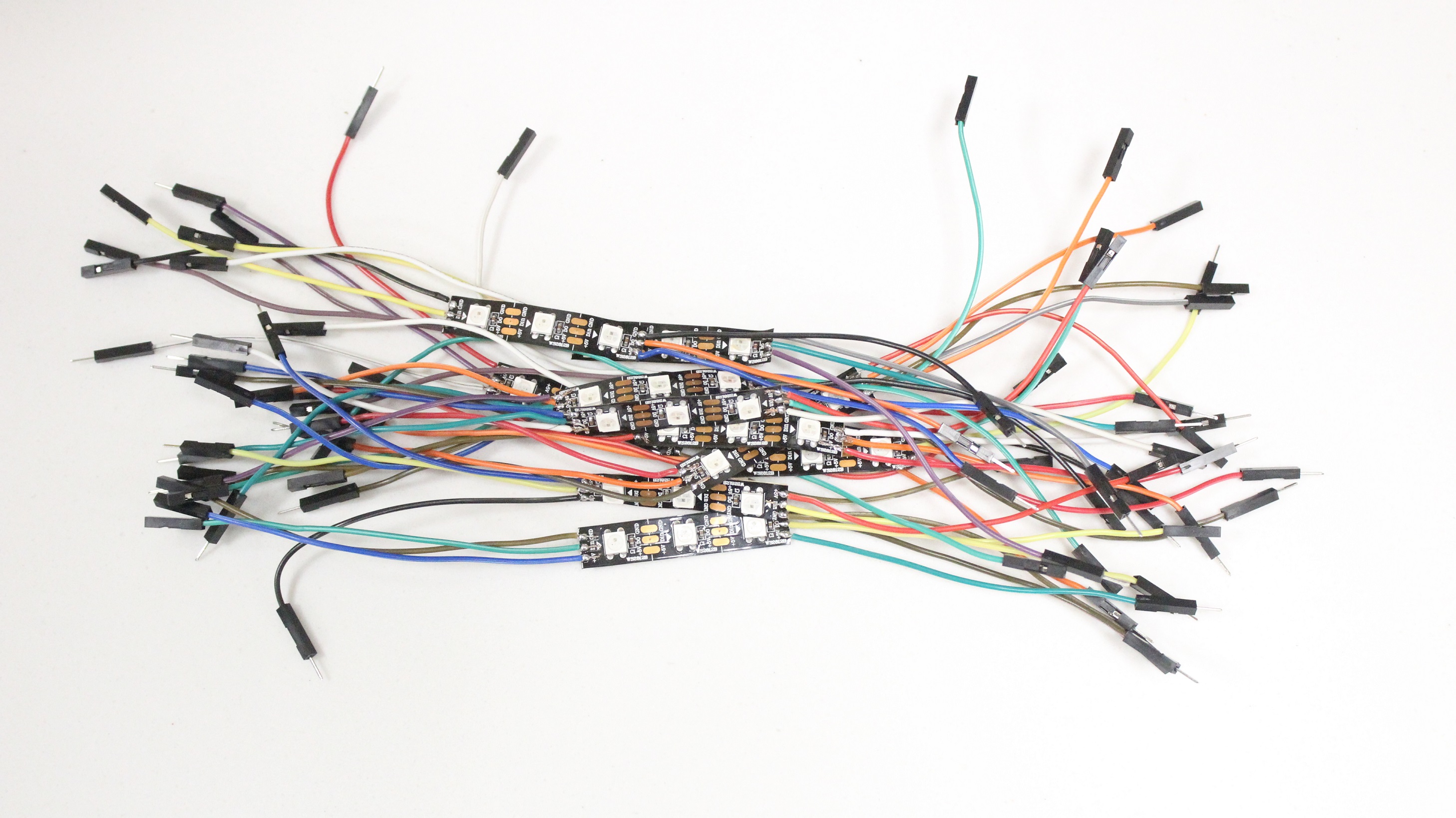
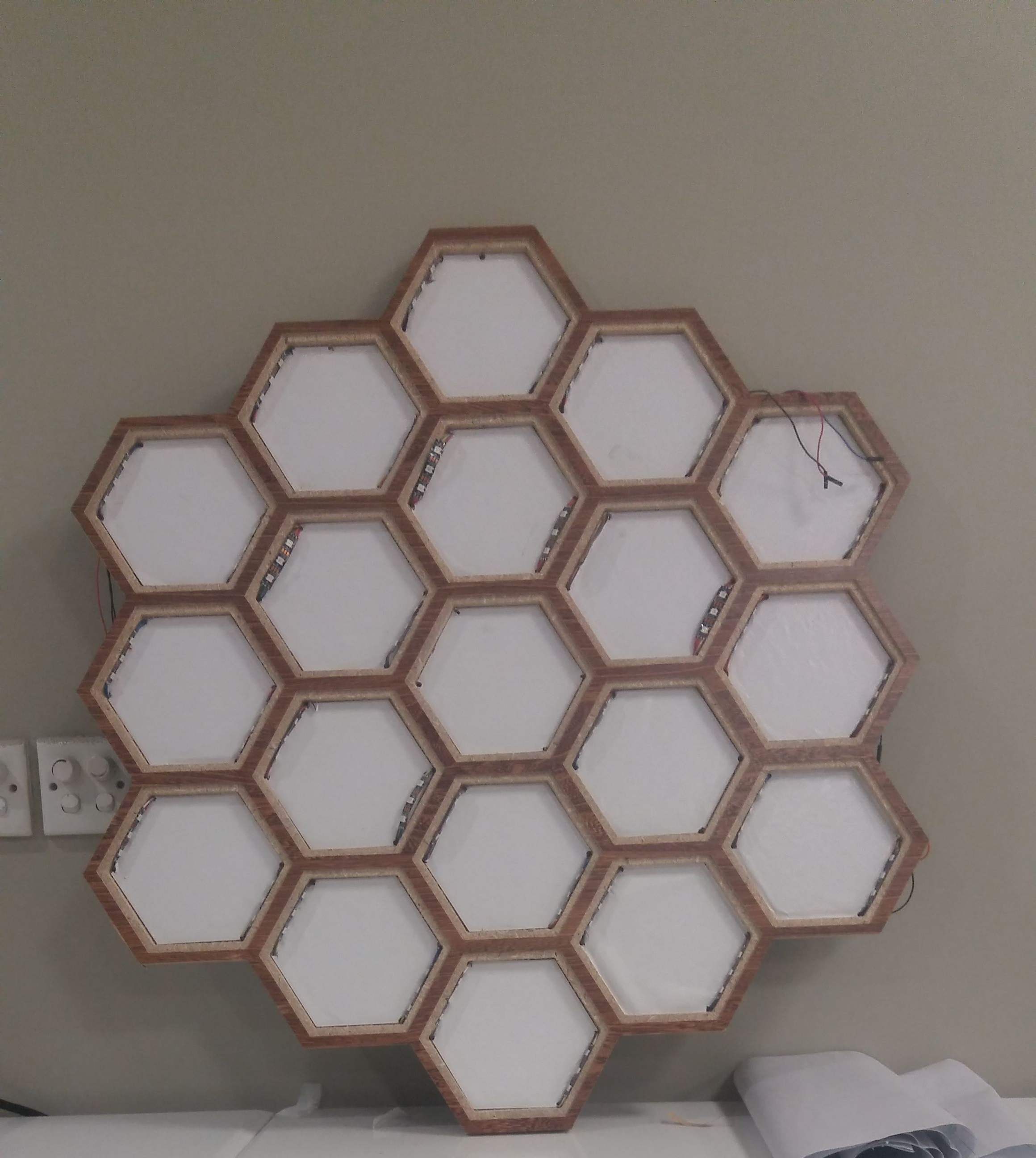
After Electronics I had to interface the rgb addressable leds to the designed body so I first calculated the number of wires I needed which were about 115 female and 115 male for whole design. I have shown that in figure (a) that male and female wires are gathered. Next step was to solder the all pair of rgb leds therefore each single strip needed six wires , 3 female and 3 male so I soldered them one by one which can be seen below in figure (b) and (c). After soldering I had to mount these leds on clock body so I proceeded further which can be seen below. As there were lot of wiring so I did tagging to each led strip section wise like I started from single hexagone and tagged that strip as 1A female with red pen and 1A male with blue pen similarly I repeated for another led strip like 1B female with red pan and 1B male with blue pen. By doing this I resoloved that huge problem of wiring. All of the rgb leds are fixed inside clock body which can be seen below in figure (d)
{ #include Wire.h
#include DS1307.h
#include FastLED.h
DS1307 rtc;
#define DS1307_ADDRESS 0x68
#define NUM_LEDS 42
#define DATA_PIN_1 5
#define DATA_PIN_2 10
#define DATA_PIN_3 9
#define R Red
#define G Green
#define B Blue
char *mycolor[] = {"Red", "Green", "Blue"};
byte second; byte secflag;
byte minute;
byte hour;
/*int i=0; int j=0; int k=0;*/ CRGB leds_1[NUM_LEDS];
CRGB leds_2[NUM_LEDS];
CRGB leds_3[NUM_LEDS];
void setup()
{
Wire.begin();
Serial.begin(115200);
//rtc.set(0, 10, 11, 12, 06, 2019); /*08:00:00 24.12.2014 //sec, min, hour, day, month, year*/ rtc.start();
pinMode(13, OUTPUT);
FastLED.addLeds
FastLED.addLeds
FastLED.addLeds
FastLED.setBrightness(255);
}
void h1off()
{
for(int i=0;i<=6;i++) leds_1[i] = CRGB::Black; }
void h1on()
{ for(int i=0;i<=6;i++) leds_1[i] = CRGB::Green; }
void h2off()
{ for(int i=6;i<=12;i++) leds_1[i] = CRGB::Black; }
void h2on()
{ for(int i=6;i<=12;i++) leds_1[i] = CRGB::Green; }
void h3off()
{ for(int i=12;i<=17;i++) leds_1[i] = CRGB::Black; }
void h3on()
{ for(int i=12;i<=17;i++) leds_1[i] = CRGB::Green; }
void h4off()
{ for(int i=18;i<=23;i++) leds_1[i] = CRGB::Black; }
void h4on()
{ for(int i=18;i<=23;i++) leds_1[i] = CRGB::Green; }
void h5off()
{ for(int i=24;i<=29;i++) leds_1[i] = CRGB::Black; }
void h5on()
{ for(int i=24;i<=29;i++) leds_1[i] = CRGB::Green; }
void h6off()
{ for(int i=30;i<=35;i++) leds_1[i] = CRGB::Black; }
void h6on()
{ for(int i=30;i<=35;i++) leds_1[i] = CRGB::Green; }
void h7off()
{ for(int i=0;i<=5;i++) leds_2[i] = CRGB::Black; }
void h7on()
{ for(int i=0;i<=5;i++) leds_2[i] = CRGB::Green; }
void h8off()
{ for(int i=6;i<=11;i++) leds_2[i] = CRGB::Black; }
void h8on()
{ for(int i=6;i<=11;i++) leds_2[i] = CRGB::Green; }
void h9off()
{ for(int i=12;i<=17;i++) leds_2[i] = CRGB::Black; }
void h9on()
{ for(int i=12;i<=17;i++) leds_2[i] = CRGB::Green; }
void h10off()
{ for(int i=18;i<=23;i++) leds_2[i] = CRGB::Black; }
void h10on()
{ for(int i=18;i<=23;i++) leds_2[i] = CRGB::Green; }
void h11off()
{ for(int i=24;i<=29;i++) leds_2[i] = CRGB::Black; }
void h11on()
{ for(int i=24;i<=29;i++) leds_2[i] = CRGB::Green; }
void h12off()
{ for(int i=30;i<=35;i++) leds_2[i] = CRGB::Black; }
void h12on()
{ for(int i=30;i<=35;i++) leds_2[i] = CRGB::Green; }
void m1off()
{ for(int i=0;i<=5;i++) leds_3[i] = CRGB::Black; }
void m1on()
{ for(int i=0;i<=5;i++) leds_3[i] = CRGB::Green; }
void m2off()
{ for(int i=6;i<=11;i++) leds_3[i] = CRGB::Black; }
void m2on()
{ for(int i=6;i<=11;i++) leds_3[i] = CRGB::Green; }
void m3off()
{ for(int i=12;i<=17;i++) leds_3[i] = CRGB::Black; }
void m3on()
{ for(int i=12;i<=17;i++) leds_3[i] = CRGB::Green; }
void m4off()
{ for(int i=18;i<=22;i++) leds_3[i] = CRGB::Black; }
void m4on()
{ for(int i=18;i<=23;i++) leds_3[i] = CRGB::Green; }
void m5off()
{ for(int i=24;i<=29;i++) leds_3[i] = CRGB::Black; }
void m5on()
{ for(int i=24;i<=29;i++) leds_3[i] = CRGB::Green; }
void m6off()
{ for(int i=30;i<=35;i++) leds_3[i] = CRGB::Black; }
void m6on()
{ for(int i=30;i<=35;i++) leds_3[i] = CRGB::Green; }
void Son()
{ for(int i=36;i<=41;i++) leds_3[i] = CRGB(255,0,0); FastLED.show(); delay(30); }
void Soff()
{ for(int i=36;i<=41;i++) leds_3[i] = CRGB::Black; FastLED.show(); delay(30); }
void loop(){ printDate(); if (hour >= 13){ hour = hour - 12;}
if (hour == 1)
{ h1on(); h2off(); h3off(); h4off(); h5off(); h6off(); h7off(); h8off(); h9off(); h10off(); h11off(); h12off(); }
else if (hour == 2)
{ h1on(); h2on(); h3off(); h4off(); h5off(); h6off(); h7off(); h8off(); h9off(); h10off(); h11off(); h12off(); }
else if (hour == 3)
{ h1on(); h2on(); h3on(); h4off(); h5off(); h6off(); h7off(); h8off(); h9off(); h10off(); h11off(); h12off(); }
else if (hour == 4)
{ h1on(); h2on(); h3on(); h4on(); h5off(); h6off(); h7off(); h8off(); h9off(); h10off(); h11off(); h12off(); }
else if (hour == 5)
{ h1on(); h2on(); h3on(); h4on(); h5on(); h6off(); h7off(); h8off(); h9off(); h10off(); h11off(); h12off(); }
else if (hour == 6)
{ h1on(); h2on(); h3on(); h4on(); h5on(); h6on(); h7off(); h8off(); h9off(); h10off(); h11off(); h12off(); }
else if (hour == 7)
{ h1on(); h2on(); h3on(); h4on(); h5on(); h6on(); h7on(); h8off(); h9off(); h10off(); h11off(); h12off(); }
else if (hour == 8)
{ h1on(); h2on(); h3on(); h4on(); h5on(); h6on(); h7on(); h8on(); h9off(); h10off(); h11off(); h12off(); }
else if (hour == 9)
{ h1on(); h2on(); h3on(); h4on(); h5on(); h6on(); h7on(); h8on(); h9on(); h10off(); h11off(); h12off(); }
else if (hour == 10)
{ h1on(); h2on(); h3on(); h4on(); h5on(); h6on(); h7on(); h8on(); h9on(); h10on(); h11off(); h12off(); }
else if (hour == 11) { h1on(); h2on(); h3on(); h4on(); h5on(); h6on(); h7on(); h8on(); h9on(); h10on(); h11on(); h12off(); }
else if (hour == 12)
{ h1on(); h2on(); h3on(); h4on(); h5on(); h6on(); h7on(); h8on(); h9on(); h10on(); h11on(); h12on(); }
if (minute >= 0 && minute <=10)
{ m1on(); m2off(); m3off(); m4off(); m5off(); m6off(); }
else if (minute > 10 && minute <=20)
{ m1on(); m2on(); m3off(); m4off(); m5off(); m6off(); }
else if (minute > 20 && minute <=30)
{ m1on(); m2on(); m3on(); m4off(); m5off(); m6off(); }
else if (minute > 30 && minute <=40)
{ m1on(); m2on(); m3on(); m4on(); m5off(); m6off(); }
else if (minute > 40 && minute <=50)
{ m1on(); m2on(); m3on(); m4on(); m5on(); m6off(); }
else if (minute > 50 && minute <=60) { m1on(); m2on(); m3on(); m4on(); m5on(); m6on(); }
if (second % 2 == 0)
{ Son();
digitalWrite(13,HIGH); }
else { Soff();
digitalWrite(13,LOW); }
FastLED.show(); delay(30); }
byte bcdToDec(byte val) {
// Convert binary coded decimal to normal decimal numbers return ( (val/16*10) + (val%16) ); }
void printDate()
{
// Reset the register pointer
Wire.beginTransmission(DS1307_ADDRESS); byte zero = 0x00;
Wire.write(zero);
Wire.endTransmission();
Wire.requestFrom(DS1307_ADDRESS, 7);
second = bcdToDec(Wire.read());
minute = bcdToDec(Wire.read());
hour = bcdToDec(Wire.read() & 0b111111);
//24 hour time
byte weekDay = bcdToDec(Wire.read());
//0-6 -> sunday – Saturday
byte monthDay = bcdToDec(Wire.read());
byte month = bcdToDec(Wire.read());
byte year = bcdToDec(Wire.read());
//print the date EG 3/1/11 23:59:59
Serial.print(month);
Serial.print('/');
Serial.print(monthDay);
Serial.print('/');
Serial.print(year);
Serial.print(' ');
Serial.print(hour);
Serial.print(':');
Serial.print(minute);
Serial.print(':');
Serial.println(second);
}
}
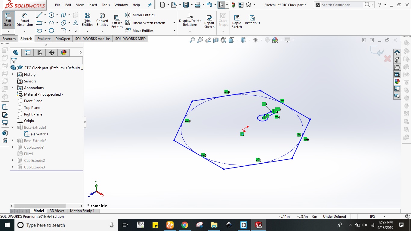
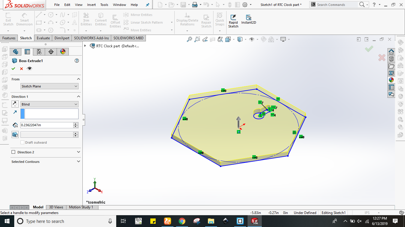
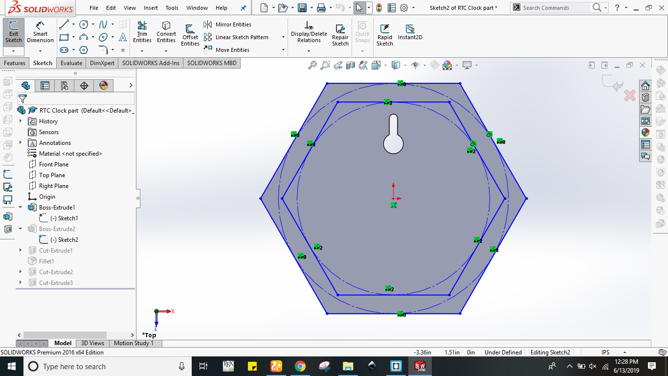
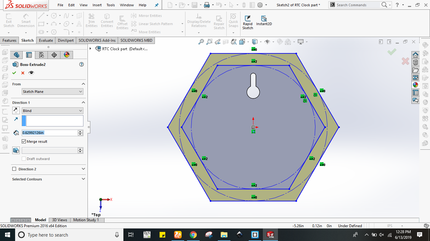
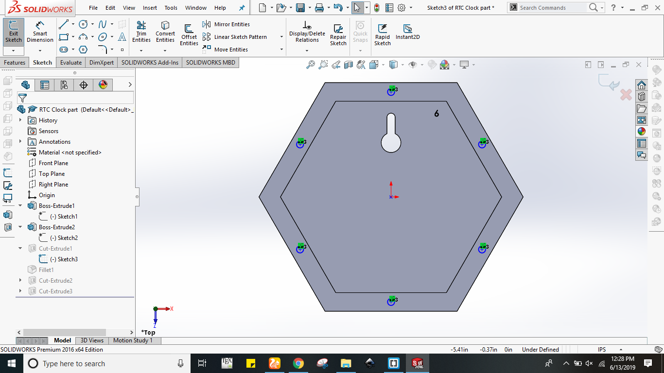
Last but not the least I needed a holding case for keeping the circuitry inside that so I proceeded with 3d designing in solidworks which is explained step by step. Initially I created a hexagon of size 3.15 inch per side which can be seen in figure(a). This hexagone also include a cut inside he shape. Next I extruded that hexagone by 0.234 inch which is shown in figure (b). After that I have created the inner hexagone which can be seen in figure below. Again I extruded the inner hexagone by 0.63inch as shown in figure (d).
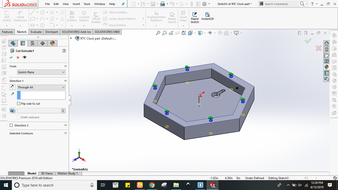
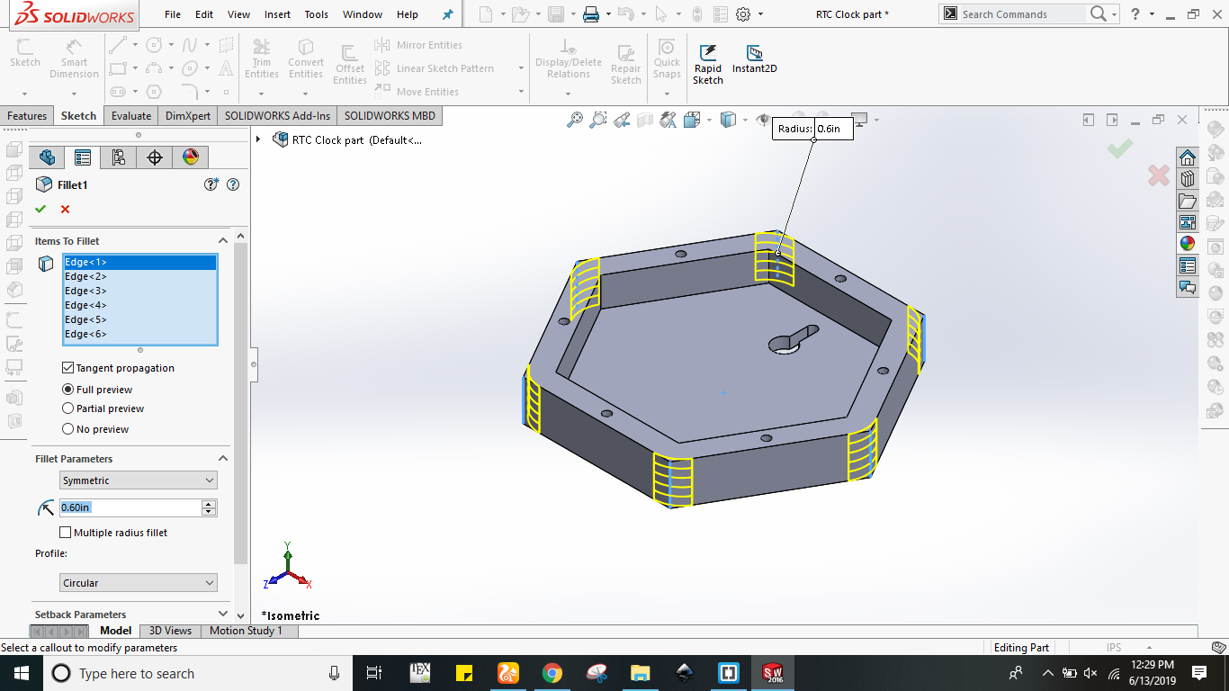
In order to fit this holding case behind the hexagonal clock I have created the circular cuts on each side which can be seen below in figure (a). Next I have used cut extrude command with through all option for these circular cuts. After doing this I have used fillet command in order to filet the edges of case. The snapshot of fillet command is given below in figure (c).
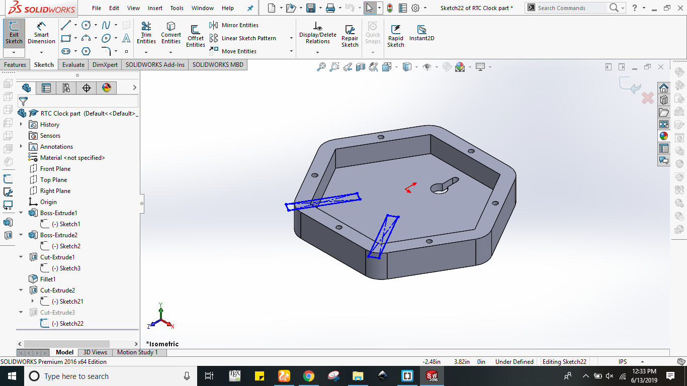
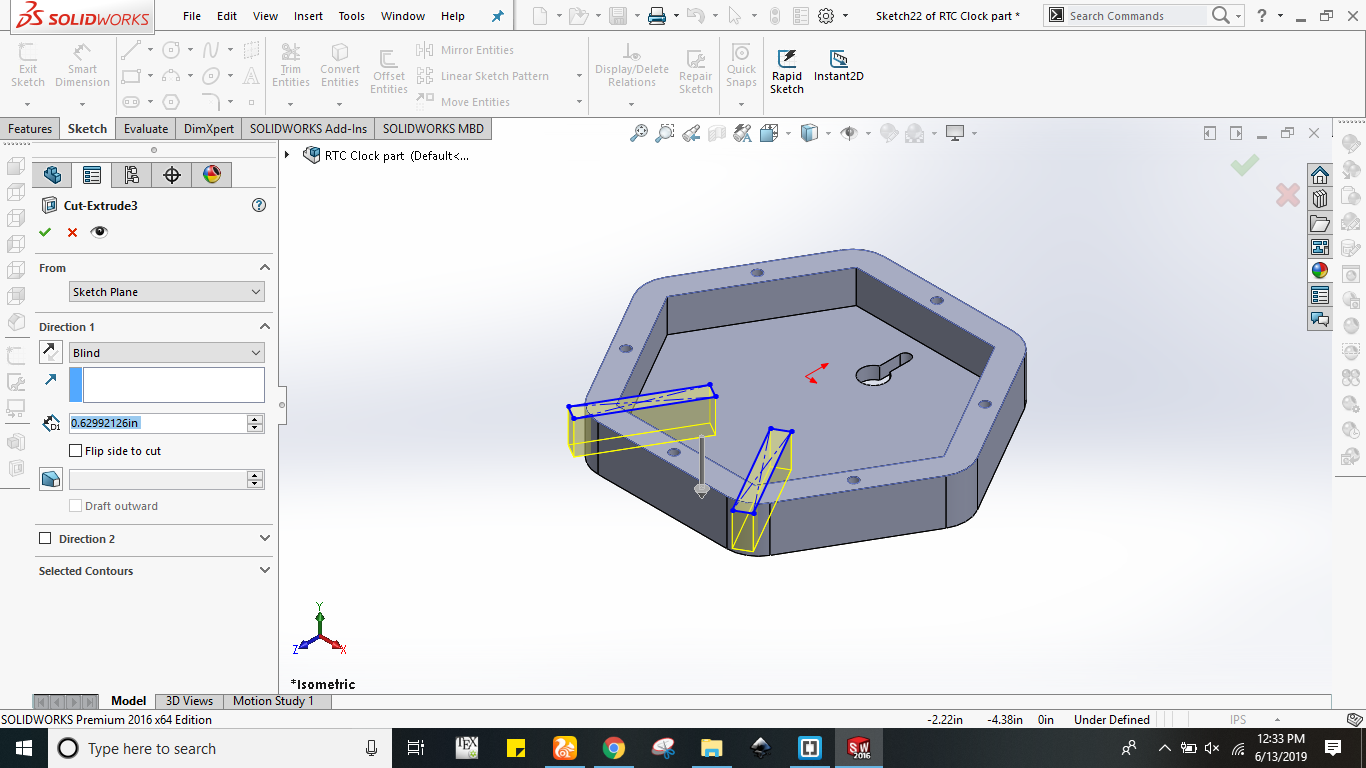
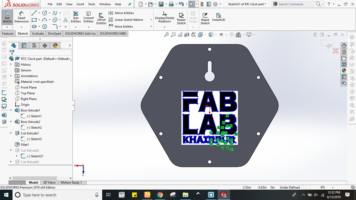
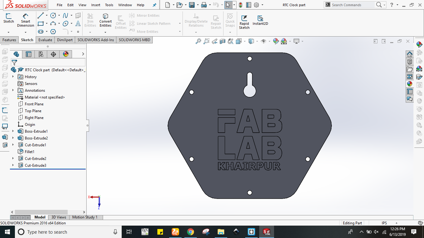
Obviously I had to pass the wiring from this holding case towards leds so for that I made wiring paths at bottom side which can be seen below in figure (a). Initially I made rectagular shape on hexagone face and then used cut extrude command for cutting the desired portion which is shown in figure (b). In last I put fab lab khairpur logo on it's backside which can be seen in figure(c). The final view of designed holding case is shown in figure (d).
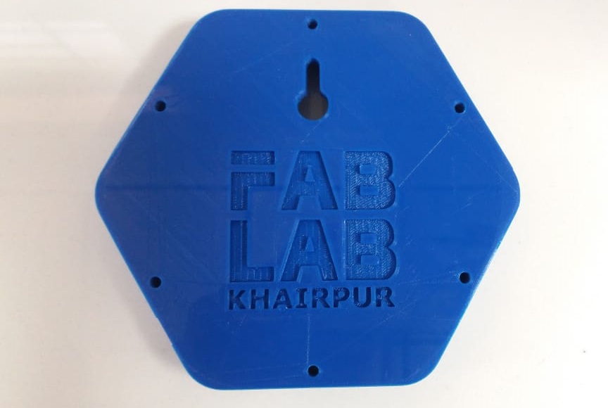
I have 3d printed the designed holding case using extendable ultimake 3d printer. I have used PLA blue material for this 3d printing of case. The figure below shows the 3d printed case.
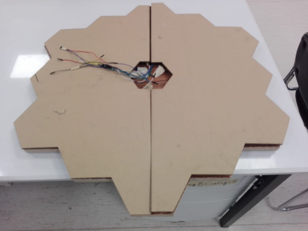
In order to make my final project like commercial product I had to finish it. Almost every thing was done except the wirings so for that I made another hexagone of clock size from cardboard. I divided it into two equal sizes just to fix that easily and I also cut small portion of holding case which can be seen below. The figures below shows the finishing of projects.
.jpg)
In last I calculated all which I used in my final project. Few parts are bought locally , few parts are bought internationally however few were available at fab inventory. All of them are given below in tabular form.
Bill of Material
| Components | Components * Price (USD) | Total price (USD) | Link |
|---|---|---|---|
Acknowledgment
First and the foremost, I would like to thank Almighty Allah for bestowing His blessings upon me
and giving me the strength to carry out and complete this work. I am extremely grateful to my Global Instructor Professor Neil Gershenfield for his awesome lectures throughout Fab diploma. I am also extremely grateful to my Local Instructors Engr. Sohail Ahmed Soomro , Engr. Noor Ahmed Pirwani and Engr. Rasheed Ahmed Qazi for their valuable advices, guidance, and encouragement throughout Fab Academy. Furthermore I would like to say especial thanks to my global evaluator Nuria Robles for such critical reviews and motivation.
Besides, I would like to give especial thanks to my faimly and friends for their support, patience and love. Without their encouragement, motivation and understanding, it would have been impossible for me to complete this work. I am very much grateful to my brother Engr. Mir Muhammad Lodro who has supported me all the way. Finally, my sincere thanks are due to all people who supported me to complete this Fab Academy diploma.