
Week 5: Electronics Production
Objectives
Learning Outcome
First we did group assignment which was to charachterize milling machine SRM 20. With the help of Instructers Engr.Rasheed Ahmed Qazi and Engr.Noor Raza Pirwani we did machine charachterization. later we downloaded the png image which shows the trace depth of machine where the lowest trace possible was 0.01 inch. Second assignment was an individual which was to fabricate, solder and program the fab In system programmer (ISP) that shall be used later for programming the other electronics boards.
Group Assignment
Step:01 The primary step in this assignment is to download the png images given below. Next generate the rml file using website fabmodules.org. There are few more steps of generating rml file which are given below.
.jpg)

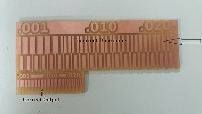
Step:02 Second step was to milling therefore we first placed the copper fr1 sheet carefully on a machine bed which can be seen below. Later we set the dimensions using SRM 20 machine software and proceded to output. Unfortunately we did mistake in setting it's dpi that is why its dimensions were too big from default size. The output can be seen below. later we tried again with setting of dimensions like dpi=2000 now the output is correct.

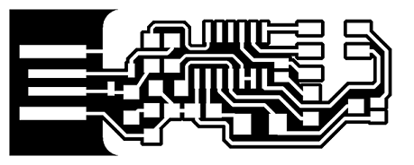
Initially I checked each circuit suggested by neil where I finalized to work with andy bardagjy fab isp which was inspired by Neil's FabISP which is based on David Mellis's FabISP which is based on Limor's USBTinyISP which is based on Dick Streefland's USBTiny. The trace and outline of isp can be seen below.

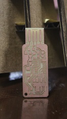
My First In System Programmer which is based on Andy. For generating RML Files and milling I follwed all the above steps of group assignment accordingly. The milling did not worked well for this fab isp which can be seen in below picture. There are lots of shorts in this isp so it is good to change the isp. I switched the hello ISP.
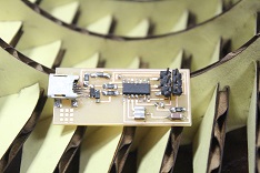
My Second Isp was hello isp 44 which worked very well. I follwed every step carefully as it is very sensitve work. The fabricated isp can be seen below in image which clearly shows that isp is fabricated very well.
.jpg)
Obviously I needed to solder this isp in order to get the output so I went electronic workbench station and collected following components to solder.
Other equipments I used while soldering
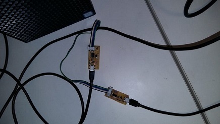
Soldering smd components is very sensitive it was very hard to work with these components. I worked almost five hours to solder this tiny isp. My second ISP after soldering is shown in below picture.
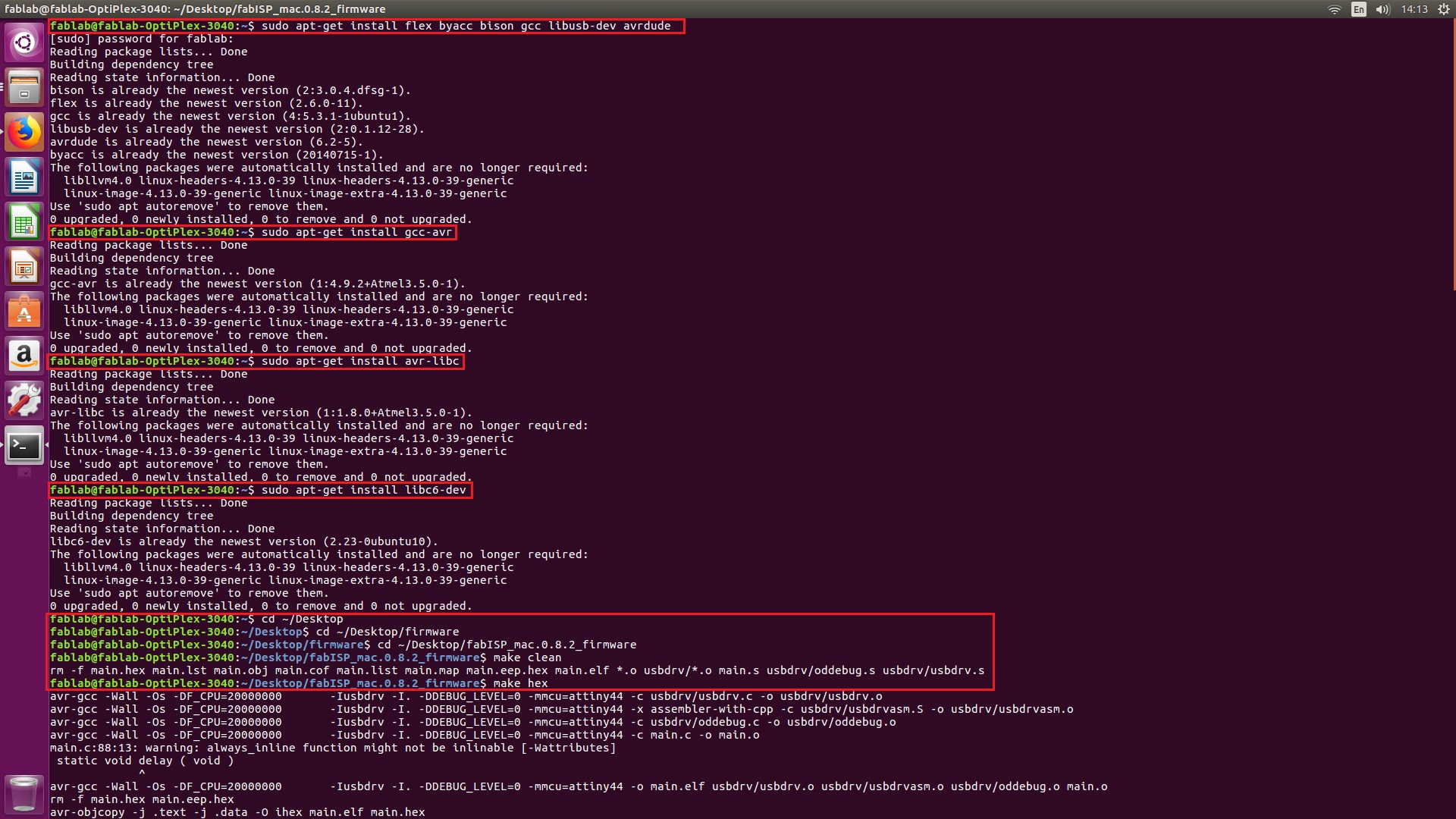
Programming the Attiny 44 fab isp. I used Linus operating system for programming my isp. I followed each and every step from this tutorial the snap shot of every step are given below.
Installing the necessary softwares for AVR Programming
Now Open the termianl and type following commands:
Then type
- type "y" when asked to do so by your system
Then type (may already be installed):
Move to the desktop
Download the firmware from the Fab Academy Electronics Production page.
Unzip the firmware
Few more steps are required to complete this operation
Program the FabISP by writing following commands in Terminal step by step:
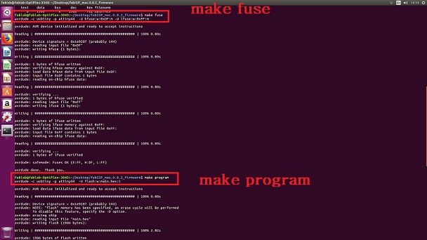
Now. Verify that your ISP is working fine by typing the following command in terminal.
Later I Removed zero ohm resistors just to make my isp able to program other boards and I download the drivers from Adafruit because it was requirement before getting its connection.
Finally I Installed the Ada fruit Drivers
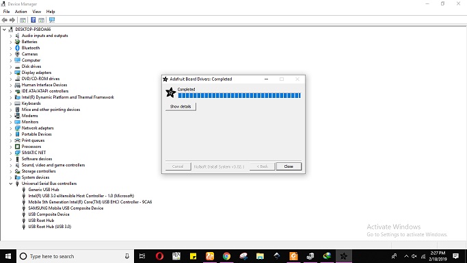
Now plug the programming isp into computer , then open the Device manager.
