Week 4: Computer-Controlled Cutting
Objectives
Learning Outcome
The real fun started in fourth week where we designed some parametric shapes in order to use computer controlled cutting. Before cutting a design on cardboard callibration of machine was essential step which was a group assignment given to us by our super guru Neil.
Group Assignment
The first group assignment was to measure kerf by making some parametric design so we made kerf testing card which can be seen below. In the kerf testing card we have introduced the eleven slots in order to measure the indentation. The card has mimimum slot width of 3.5mm and maximum slot width of 4.5mm. Since we have cardboard of 4mm thickness therefore we started from initial slot of width 3.5mm to 4mm so we checked the all slots by putting the teeth inside of each slot and observed that 3.8mm was quite accurate however above 3.8mm slots were not fixed. In the end the result is that indentation is 0.2mm of whole slot due to card thickness. Hence we can say that reasonable kerf is 0.2mm/2mm=0.1mm

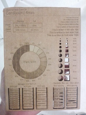
The second objective was to design material tesing card which shows different types of material tests. we used cardboard of 4mm thickness just to test the speed and power of epilog laser cutting machine by predefined sample found on internet. The picture of printed material test cardboard can be seen below.
Material Test Card Board
Press-Fit Parametric Design
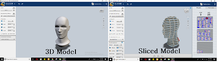
In this week our second task was to design any press fit parametric structure using cardboard. Professor Neil Gershenfeld strongly recommended to use good quality of card board for press fit kit. After lecture I started to search number of press fit ideas in pinterest and google. I was very much excited to design the complex structures like animals or birds which I tried to design those in fusion 360 where I used pre defined models which can be seen below.

The above picture shows the pre defined model of lamp which is taken from fusion 360 to slicer 360 for the purpose of pressfit kit. I really enjoyed this software because it gives you run time output. The below picture shows man head which is also imported to slicer 360. On the left side it is 3D model however on the right side it is sliced model of man head. The next step could be done is to get dxf or pdf file and print using laser cutter machine and assemble them in order to have pressfit kit.
It was awesome to work in fusion 360 and its adon slicer 360 but solidworks was more versatile, flexible and easy to handle so I decided to choose solidworks over fusion 360. Basically solidworks is assembly driven software which mean it build parts individually before assembling them in a separate file however fusion 360 is multi componenet part system where components are assembled in a a same file. By the time I tried to find simple and cool ideas which can work better as parametric pressfit kit. Among all of them wine keeper or bottle keeper looked cool to design for assignment so I started to design that kit using solid works with parametric equations which means that I can change this design from smaller to bigger size with different materials for example here I have used 4mm thick card board but if I want to make same design in shopbot I just change the thickness value of material thickness equation to 16mm. By this I will be able to resize my design. The method of designing the wine keeper is given below step wise.
Step:01 Create a rectangular with length of 12 inches and width of 6 inches and fillet each corner of rectangular by 1 inch using fillet command.

Step:02 Create a circle at 1 inch distance from every side. The diameter of circle should be 4 inches because usually bottles diameter is 3.2 inches. In order to create a second circle I used mirror command which copied the circle on exact opposite position. Note there is 2 inch gap in between two circles.
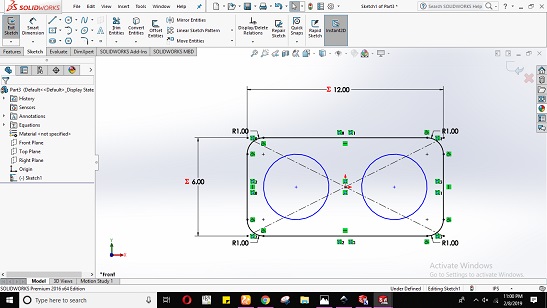
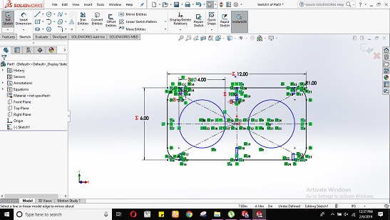
Step:03 Create a rectangular slots with constant width size of 0.16 inch (4mm because of sheet thickness). The center slot length is 1 inch however corner slots has length size of 0.5 inch. In oreder to have the slots on opposite side I used mirror entity command which copied the all three slots on the opposite side. These slots are introduced in order to insert the designed sticks which are responsible to support the strucure.
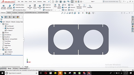
Step:04 Now it is time to extrude the designed shape by 1 inch and cut the rectangular slots using extrude cut command. The after effect shape can be seen below.
Step:05 Next step is to design the sticks of variable width because they are used at different points. I have defined three width types in equations where width variable represent to 0.75 inch size, width one equals to 1.25 inch size and width 3 was of size 2inch. In case of length we have bottle length 9 inches so it is essential to set the length of stick to 9 inches.

Step:06 It's time to laser cut the sample of pressfit design but before that we need to do some steps as given below.
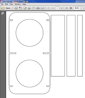
Caution: Before getting pdf file you must check the dimensions as I designed my model with measurement unit inch so I got it in mm value in incscape software. This software considers all your dimensions in mm values. Here is the trick to resolve that. copy the values given in mm values and select measurement unit type inch and paste. After resloving it go to document properties and set sheet size to Arch E type. Further more you should also take care of stroke size which should be clear enough for laser cutter. You should place the file in to upper corner with maximum size utilization of cardboard and minimum wasting of cardboard. Later export as pdf file and save it with some title name. Pdf screenshot can be seen of sample pressfit design.
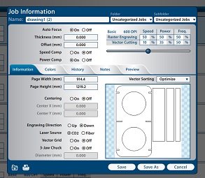
Step:07 Now open the pdf file and give print command to epilog laser cut machine. Later open the software of epilog lasercut machine and check weather your file is reached or not. If file is reached go to preview and see either your file is ready or not. Please check both types raster and vector. After that set the speed and power of machine to reasonable values in my case I have set 10% speed and 35% power for vector cutting which can be seen below.
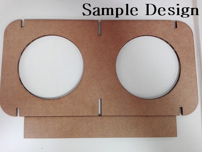
Step:08 Sample design after cutting on laser cut machine is shown below. In this sample I set the width of slot 4mm because of carboard thickness. Since we knew from group assignment that kerf matters similarly in this sample it also became visible that designed stick was not sitting well inside the reck. Therefore I needed to adjust kerf of 0.20mm so I changed the slot width value to 3.81mm=0.15inch. Here I found the benifit of parametric design as well that I just changed the single parameter value only and whole design changed accordingly can also be seen below in snapshot. There are many variable defined for example length, width etc of rectangular box which can be adjusted accordingly.

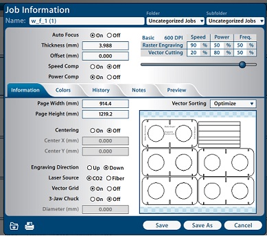
Step:09 After adjusting kerf I need to cut my real design therefore it is necessary to repeat the step 6 and step 7. In step 7 set the speed of raster engraving to 90% and power to 50% however for vector engraving set the speed value 20% and power value 80%. Both quantities can be seen clearly in given picture.
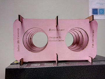
Step:10 Press Fit Design is Ready. I placed my water bottle and Enjoyed!!
Front View
Vinyl Cutting Design
3rd and final task of the week was to cut something on vinyl cutting machine. Initially I tried to trace my picture in inkscape using line art and beizer tool curve which can be seen below. Later I found some new vector images which attracted me so I changed them to vector image with some process. There are few steps to turn any image into vector image.

Step: 01 Import Image in incscape software.
Step: 02 Trace bitmap image. Use command Shift+ALT+B which shall open a dialogue box of trace bit map where you shall adjust your image as it looks good. Now go to document properties and set the image size which you need. Later export as png and set dpi to 300 and press export button.
Step: 03 Please open the saved png image in paint and save as JPEG and bitmap file type. You are all done with software now its time to cut image in roland machine.
I made three pictures in vector format which are clearly visible below.

.jpg)
Setting Roland Machine
1. Insert paper carefully of image size you want to cut.
2. Set the piece(in case you have piece of paper). The machine will give you dimesions of paper.
3. Look if machine is ready to cut.
Putting command using roland gs software
1. Open roland software.
2. Import the bmp file size picture.
3. Recheck your image dimensions.
4. Click on image => right click => extract contour lines and remove your orignal picture.
5. Click move botton to place image to bottom.
6. Set the dimension of your file => go to cutting => change (button of media size) => press get from machine.
7. Press ok to cut.
Finally FabWorks for Dreamworks!