
|

| Sukkur IBA University Khairpur Campus Merit, Quality, Excellence |
Week - 12
Output Devices
Assignment
Group Assignment
- measure the power consumption of an output device
Group Assignment
In this week group assignment we have to measure power consumptions of an output device.I Have used Led Strip as output device So I measured power consumptions over a individul Led in strip.
As one of our project is on RGB LEDs so we decide to find the power consumption of RGBs on different color pattern We write some codes which blink 1 RGB with specific color and measure current on that project
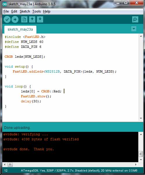
Program For One Led
Voltage Across LED Strip
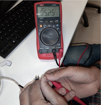
Current Across RED LED
The current is measured 47mA which is multiplied with 5 Volts is equal to 235mW
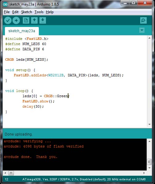
Pogram For Green LED
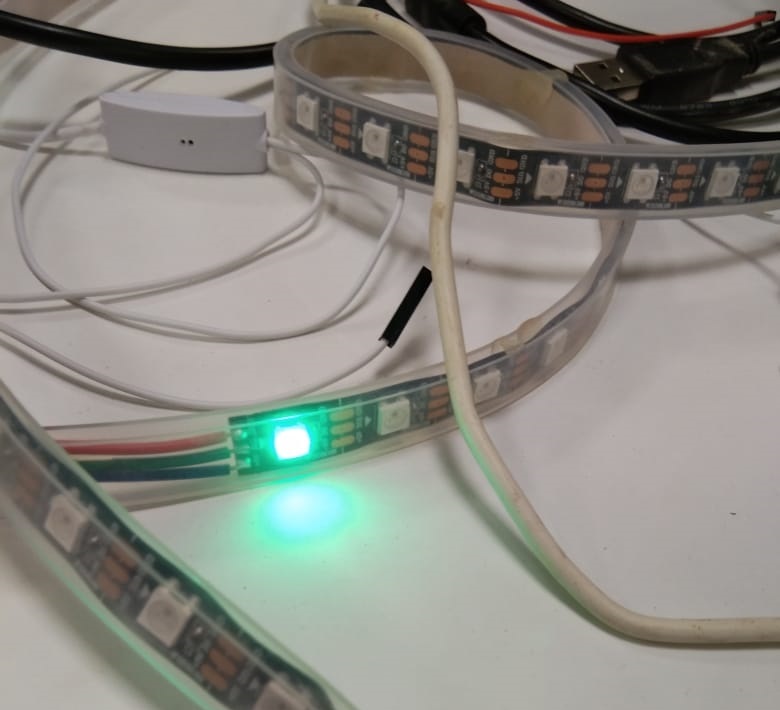
Green LED
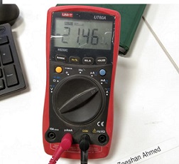
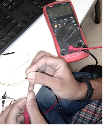
Current Across Green LED
The current is measured 21.46mA which is multiplied with 5 Volts is equal to107.3mW. Same procss is used for other colors too.
Individual Assignment
- add an output device to a microcontroller board you've designed, and program it to do something
Individual Assignment
I planned in this week to make a board, which is not only use in this week but kind of general purpose board for me, and for that I need more pins then ATtiny45 or ATtiny44 thats why I choose to work with ATMega328p which is 8-bit microcontroller with 32 pins, which was made by Ex-student Noor Ahmed Raza Pirwani i took schematic files and Re-rout the board and make a small board as i could.A datasheet is downloaded from here .
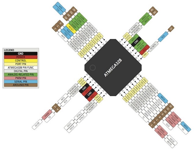
ATMega328p Pin Description
PCB Designing
For PCB designing I worked on Eagle 7.5 (an introduction of this software is mentioned in Electronic Design Week).I removed zero resister which was extra in schematic of board:
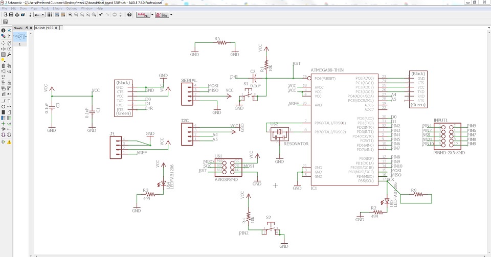
328p Board Schematic
then I generate PCB board and route it.
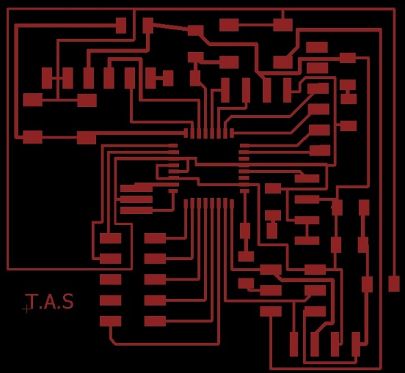
PCB Design
Generating .RML Files
For generating RML files, first I need my PCB design in .png format for that I export my PCB design in .png while setting up 2000 dpi and Monochrome
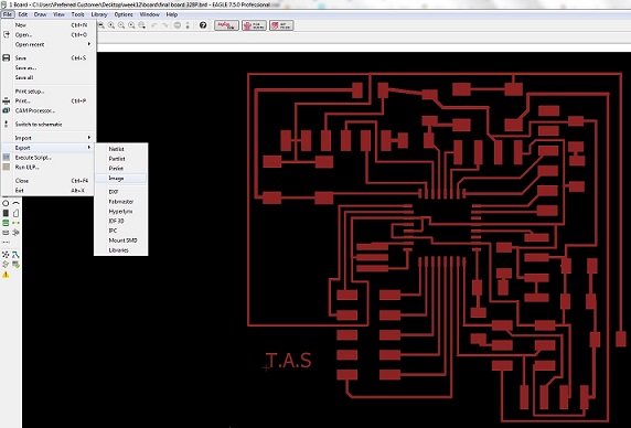
Exporting image
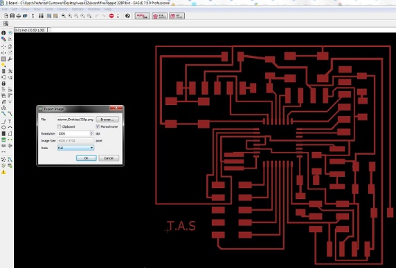
Setting 2000 dpi and monochrome
.png is processed in Paint for making seperate files for traces and outline of a PCB design (in a case of drill holes in PCB one more file is made)
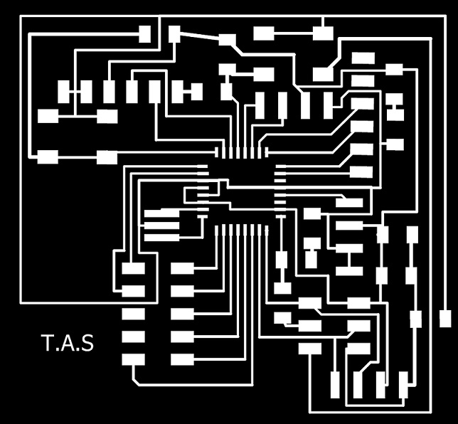
PCB traces

PCB Outline
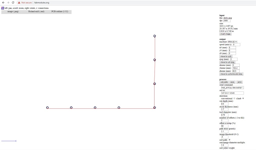
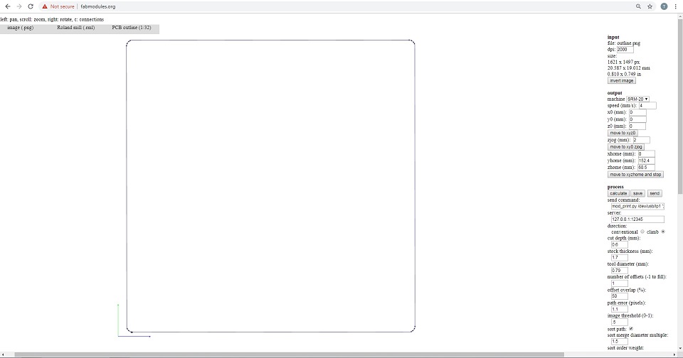
after making traces and outline of a pcb I used fabmodules to generate RML files of both traces and outline, all important settings are mentioned in a pictures below, for detailed fabmodules settings visit Electronics Production Week
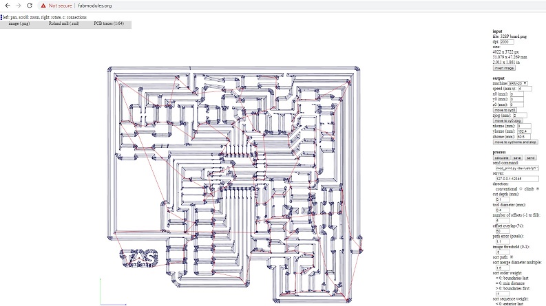
generating .rml file of PCB traces
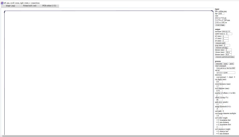
generating .rml file of PCB outline
Milling and Soldering
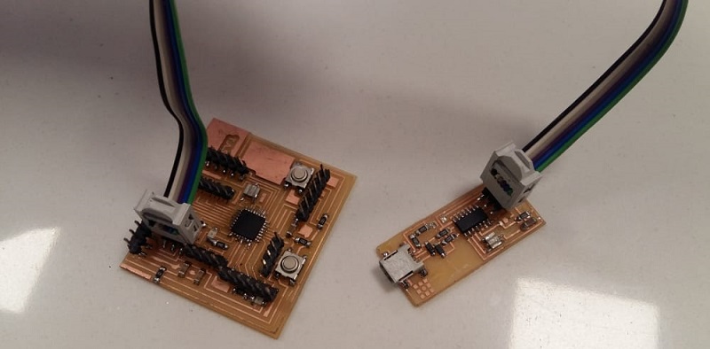
.rml files are given to Roland SRM-20 for milling, 1/32 drill bit is used for cutting outlines and 1/64 bit drill is used to make a trace on a board and here is the result.
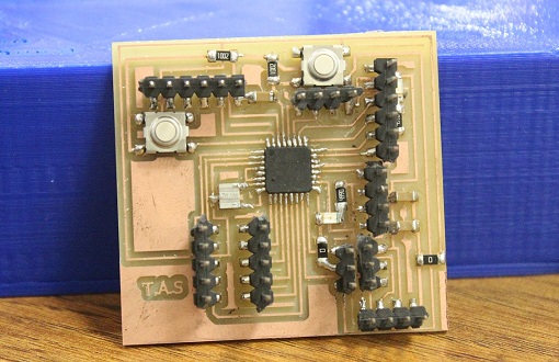
328p Circuit Board ready to Burn
328p Board Features:
- Support Programming from FTDI Cable
- One general purpose button connected with Pin2 of Arduino
- Dedicated I2C Connector
- Dedicated Serial Connector
- General Purpose 4 Analog Pins A0, A1, A2 and A3
- General Purpose 8 Digital Pins in which 5 pins are PWM~. Pin3~, 4, 5~, 6~, 7, 8, 9~, 10
- LED is connected with Pin13 to work with LED_BUILTIN codes
- Dedicated 2x3 ISP Pins
- Controller RESET button
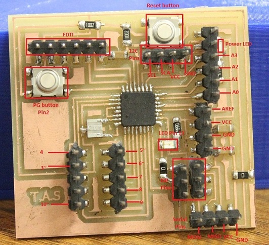
328p Board Pin Description
Voltage Regulator board
After making 328P board i made a voltage regulator board to protect my 328P microcontroller
PCB Designing
For PCB designing I worked on Eagle 7.5
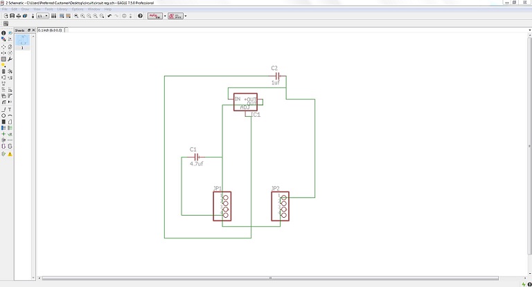
Voltage regulator Board Schematic
then I generate PCB board and route it.
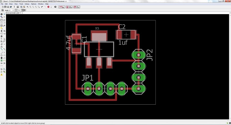
PCB Design
Generating .RML Files
.png is processed in Paint for making seperate files for traces, outline and drills of a PCB design
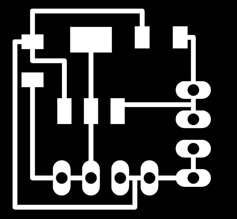
PCB traces

PCB drills

PCB outline
after making traces and outline of a pcb I used fabmodules to generate RML files of traces, drills and outline
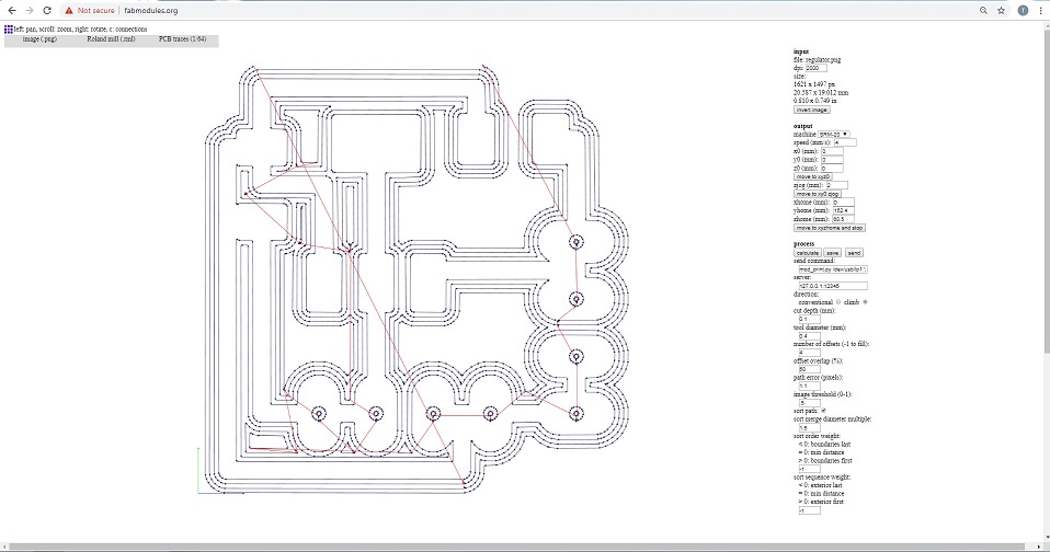
generating .rml file of PCB traces
generating .rml file of PCB drills
generating .rml file of PCB outline
Milling and Soldering
.rml files are given to Roland SRM-20 for milling, 1/32 drill bit is used for cutting outlines and 1/64 bit drill is used to make a trace on a board and here is the result.
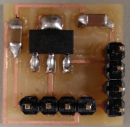
Voltage regulator Board
Programming the board
To program a board I need an ISP programmer, I made one developer board in Electronics Production Week.
I am using Arduino IDE for programming my board. Before programming the board first it is required to burn bootloader in it. For setting up Arduino IDE to work with FabISP I mentioned in detail in Embedded Programming Week. The bootloader burn in board using FabISP which is One time process then after that I use FTDI Cable to program my board. Below I shared some steps to burn bootloader in my board:
Connect 328p board with FabISP and connect it with PC
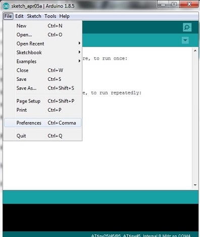
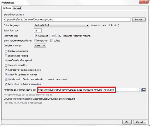
Now from: MiniCore first copy and past this link
"https://mcudude.github.io/MiniCore/package_MCUdude_MiniCore_index.json" into File > Preferences > "Aditional Board Manager URLs"
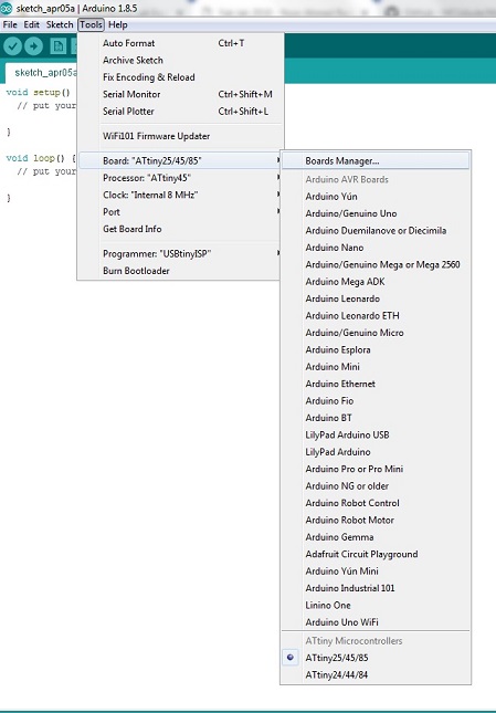
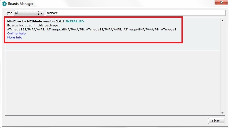
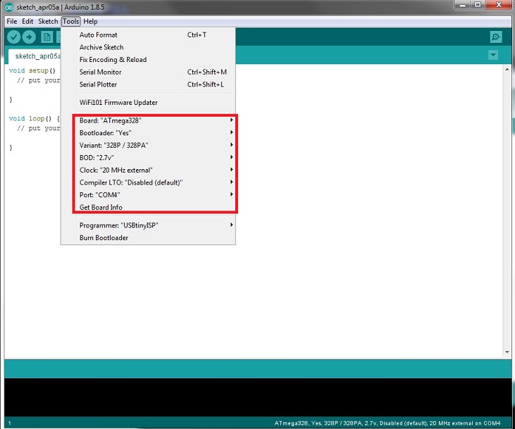
Now goto Tools > Boards > Board Manager... and install MiniCore by MCUdude
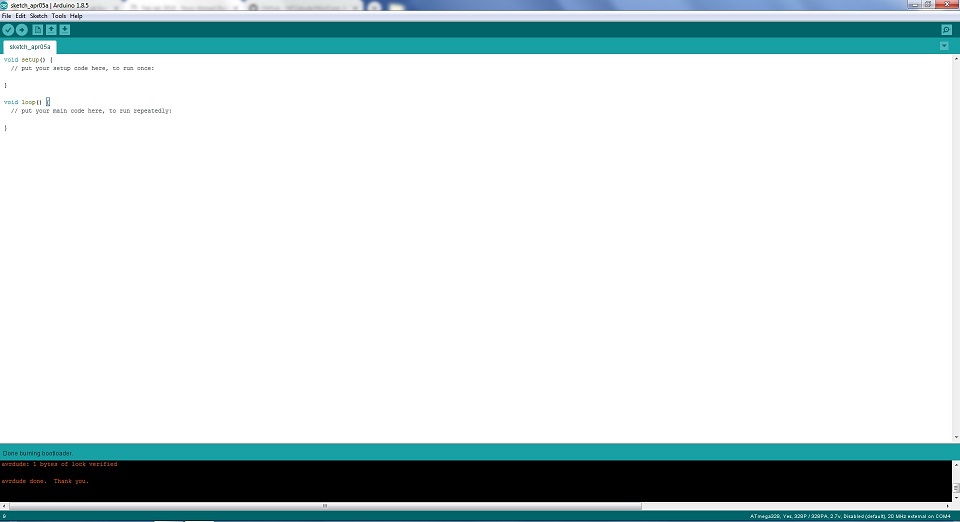
These are the settings which I mentioned below before burning bootloader, set it up and click Burn Bootloader
Burning bootloader successfully now we test board with Blink Code which is present in Arduino examples, to check either it is working or not.
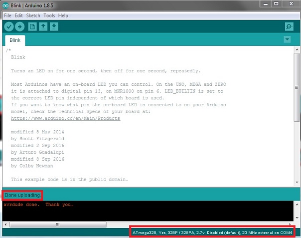
Blink Code Successfully upload in 328p Board
After Blink code successfully upload and run in 328p board now It is time to connect servo motor with board and program it to run at differnet angles.
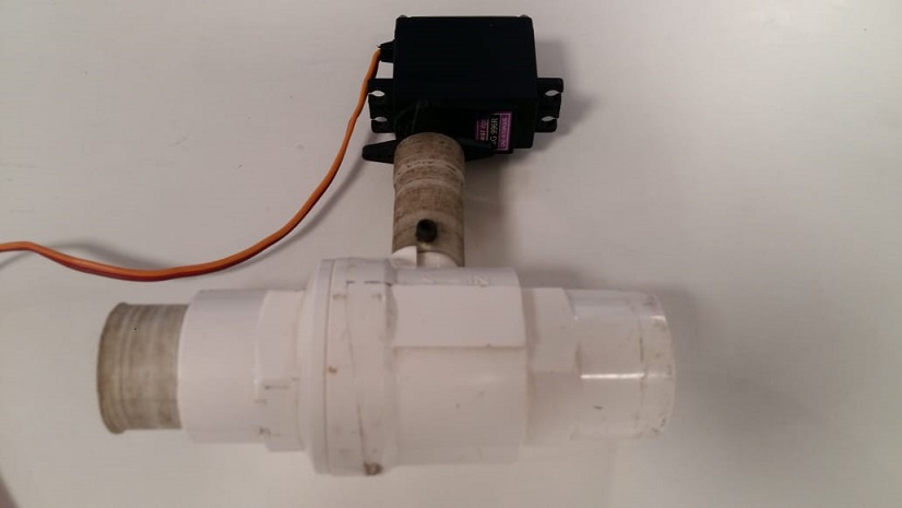
Servo motor with Ball valve
Making Connections
Connect Servo motor pin with Pin-3 of 328p board and connect supply pins VCC and Gnd with external source. I am using external source here because it is difficult for 328p board to draw more current
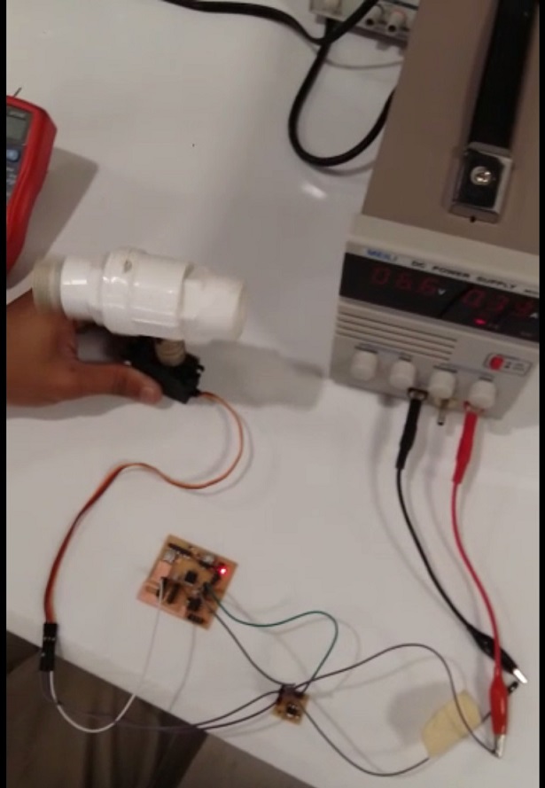
I found one code with different angles motion from this link and upload it in my 328p board
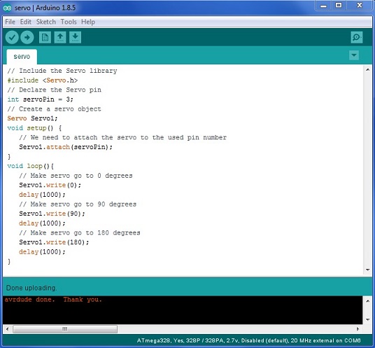
The code is working perfectly and the results are shown in below video
"Click here"to download all files of this week

Automatic Hot Water Dispenser by Tariq Ahmed Shaikh is licensed under a Creative Commons Attribution-ShareAlike 4.0 International License.
Based on a work at http://fabacademy.org/2019/labs/khairpur/students/tariq-ahmed/