|

| Sukkur IBA University Khairpur Campus Merit, Quality, Excellence |
Week - 7
Electronics Design
I began this week by going through all the basics again. The last time was about what a PCB is, it's type and the components on the PCB. This week was how to use them create your own board, by drawing a schematic drawing for the same. So before I begin drawing a PCB I need to know the basics of a circuit. What is a circuit, how electricity flows through different components?
Circuit
An electronic circuit is composed of individual electronic components, such as resistors, transistors, capacitors, inductors and diodes, connected by conductive wires or traces through which electric current can flow.
Voltage
Voltage is what makes electric charges move. It is the 'push' that causes charges to move in a wire or other electrical conductor. It can be thought of as the force that pushes the charges, but it is not a force. Voltage can cause charges to move, and since moving charges is a current, voltage can cause a current.
Current
An electric current is a flow of electric charge. In electric circuits this charge is often carried by moving electrons in a wire. It can also be carried by ions in an electrolyte, or by both ions and electrons such as in an ionised gas (plasma).
Resister
Resistor is an electrical component that reduces the electric current.
Integrated Circuits
An integrated circuit, or IC, is small chip that can function as an amplifier, oscillator, timer, microprocessor, or even computer memory. An IC is a small wafer, usually made of silicon, that can hold anywhere from hundreds to millions of transistors, resistors, and capacitors. These extremely small electronics can perform calculations and store data using either digital or analog technology.
Assignment
Group Assignment
•use the test equipment in your lab to observe the operation of a microcontroller circuit board
Individual Assignment
•redraw the echo hello-world board • add (at least) a button and LED (with current-limiting resistor) • check the design rules, make it, and test it • extra credit: simulate its operation
Redraw the echo hello-world board
In this week we have task to learn Eagle and Kicad software because with the help of these software we can draw/ redraw circuit easily,and PCB board can be generated. To redraw the echo hello-world board there are several steps to follow which I describe below:
•Download and install Software
•Download and install FAB libraries to get the list of components which are available in FABLAB
•Enlist the components which is seen in given hello-world board. •Redraw the echo hello-world board by adding input and output in it i.e, atleast one button and LED with current-limiting resistor
•Generate .rml files of traces and outer boundary of PCB
•Mill the PCB by giving .rml file to ROLAND SRM-20 milling machine
•Sold the components on PCB
•Test the board by burning program in it.
CadSoft Eagle

Eagle is PCB designing software. Its a really powerful software with really great features. As post to manual designing, these software really help make life easy. The software is very easy to use and is merely drag and drop. The software can be download from Here
FAB Library
After installation of CadSoft EAGLE we need to include fab library in it, the library help us to get the proper PCB layout of the components in software which are available in FABLAB.The FAB library is downloadedfrom Here
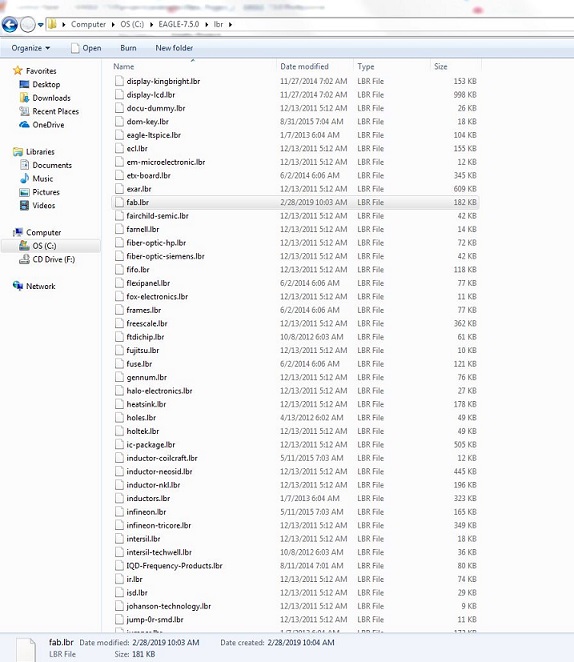
•If installation of a software is in default location then to include fab library we just need to paste the library in the folder C:\EAGLE-7.5.0\lbr.
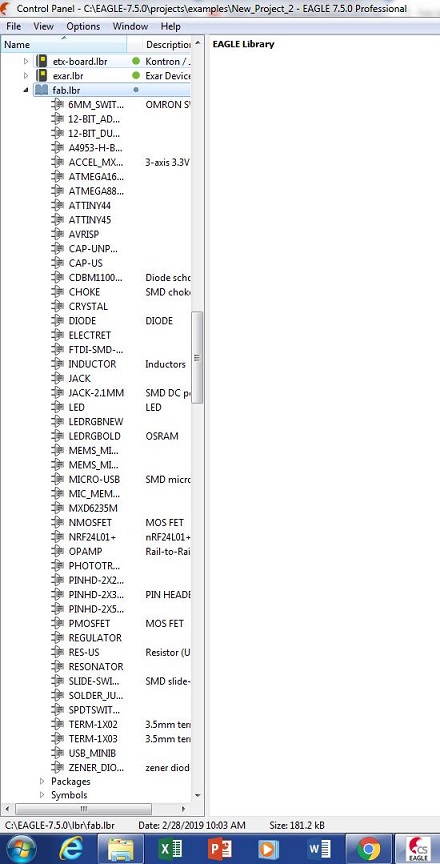
•After opening EAGLE, a Control Panel is shown on screen, we can check in it either library is included or not
Scheme
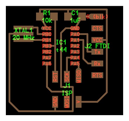
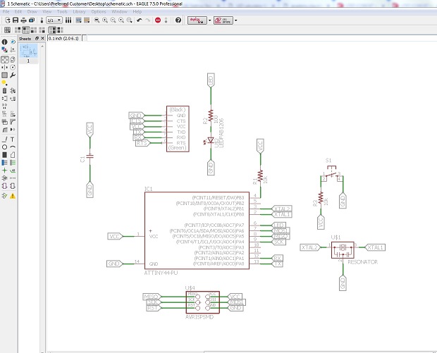
The task is to redraw the Hello-Echo board. This is the scheme of the board
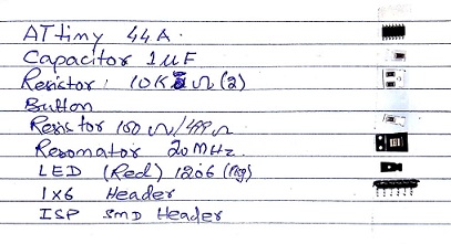
These are the list of components required to design this board
Component list:
- 1x ATtiny44
- 1x 10kΩ resistors
- 1x 1uF Capacitor
- 1x FTDI Header
- 1x 6 pin AVRISP Header
- 1x 20Mhz Resonator
Additional components:
- 1x Red LED
- 1x 10kΩ resistors
- 1x 100Ω resistors
- 1xPush button
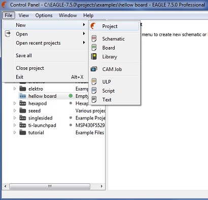
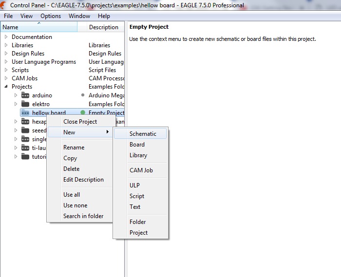
start new project by selecting "New" in "File tab" then select "Project"
After clicking on Project to Schematic, an "Empty Project" is made in Eagle folder. Rename it and right click to open schematic
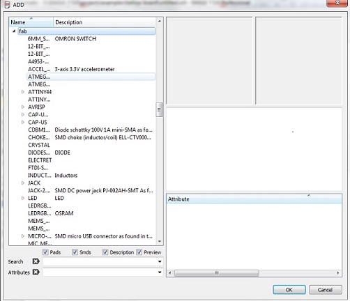
For making schematic circuit,we have to add components from "add tool" at left side tool bar then new window opens and choose components from fab library.
After adding tool, we have to join them for completing schematic. There are two ways to do so. First is using the net tool to join the desired components. This is easy and great but the problem is there are a lot of crossing of lines and it's easy to get lost especially when its a big circuit.
The second way is to provide net on all connectors and when right clicked a menu opens up and using the name tab, you can name the net. When two nets have the same name they automatically connect. They connection make not show up in the scheme but will show up on the board.
Once all the connections are complete we can switch schematic to PCB board.
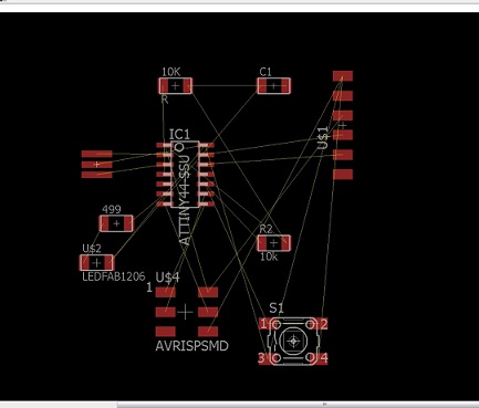
Now arrange the components in the desired shape, but keep in mind that during placing the components avoid crossing of the line.
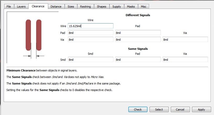
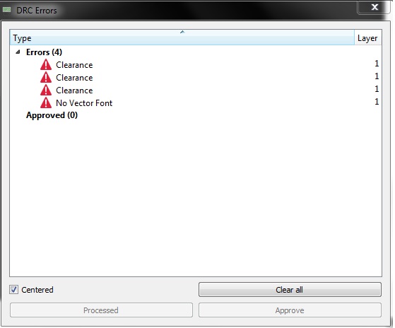
Board is completed and go to DRC (Design Rule Check) command,in clearance i put the value endmill 1/64" in 15.625 mil.
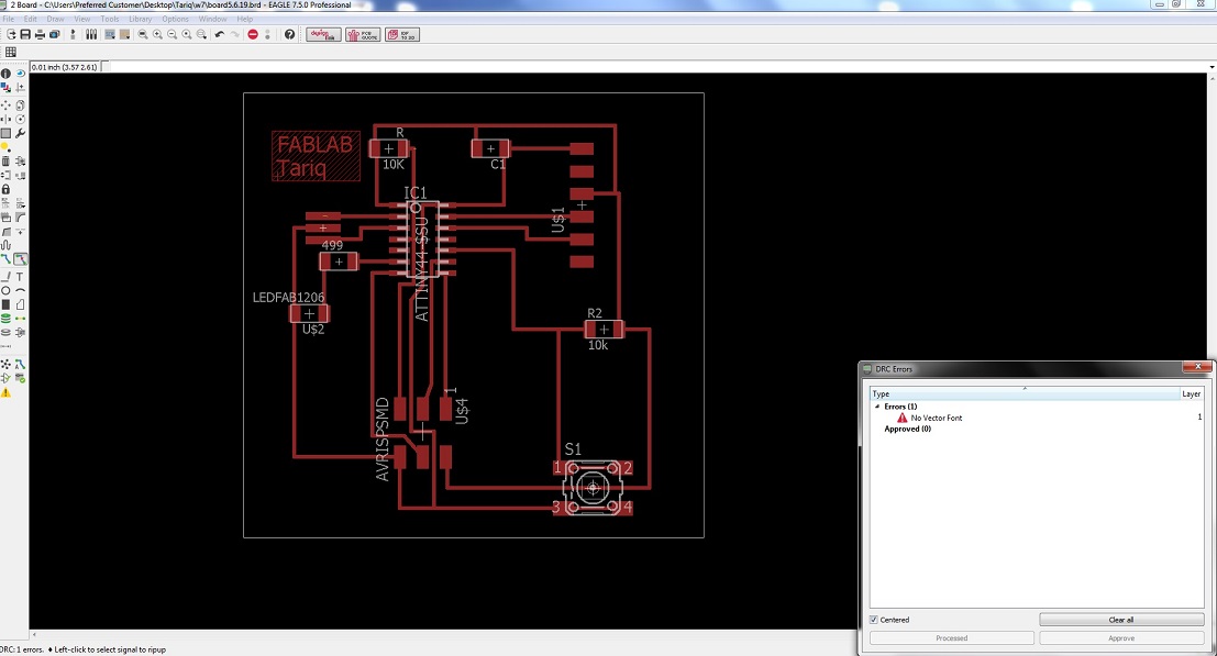
i got four errors.
Than i re-rout the mention parts and check it again now it is ok.
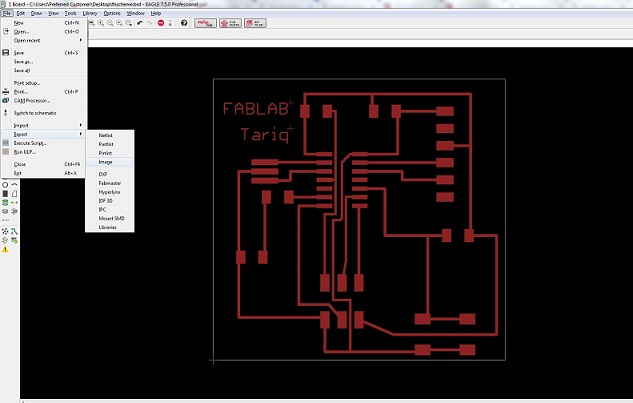
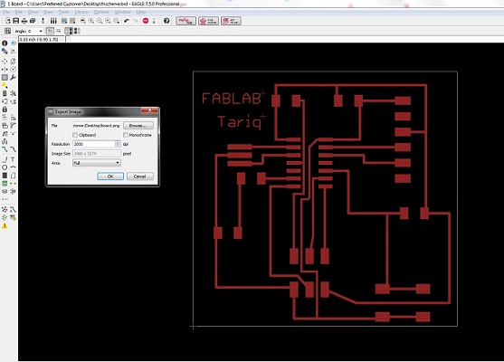
The designing was done. Now its time to export it for trace and cutting.
then resolution set at 2000 dpi and select monochrome
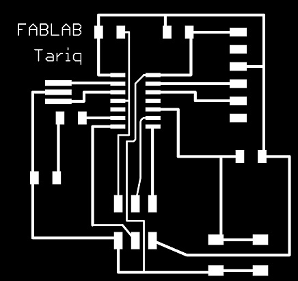
when png file was generated, open it in paint for making traces and outline file for generating .RML file then further process in Roland SRM-20 Milling machine
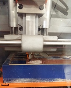
Milling and Soldering
.rml files are given to Roland SRM-20 Milling Machine. For traces 1/64 drill bit and for outline we are using 1/32 drill bit
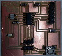
list of components which we use in PCB board.
Then solder the all components in PCB board include button and LED.
Group Assignment
Group assignment for this week was to check the operaion of micro-controller board by using various electrical equipments.
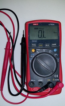
The equipments in our lab is as follows:Multimeter:
This device has multiple function such as, measure current, resistance, and voltage.
Multimeter
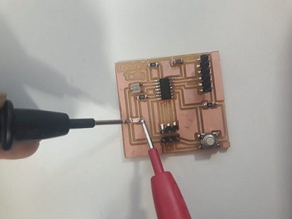
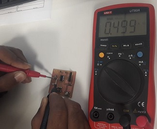
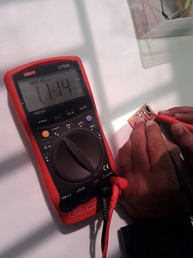
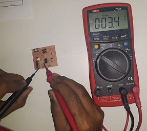
We used it to check the polarities of the LED, resistance and capacitance and the continuity of the circuit board.
LED testing
Resister Measuring
Capacitor Measuring
Checking continuity
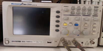
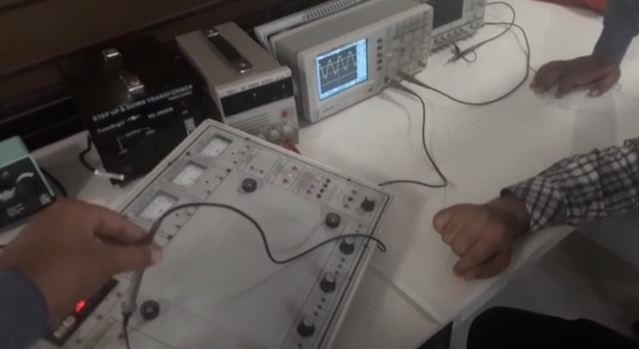
Oscilloscope:
oscilloscope
Oscilloscopes are used to observe the change of an electrical signal over time, such that voltage and time describe a shape which is continuously graphed against a calibrated scale. With the help of oscilloscope we tested function generator of electrical kit.
wave in the form of sinusoidal
"Click here"to download all files of this week
« Week6 Week8 »
Automatic Hot Water Dispenser by Tariq Ahmed Shaikh is licensed under a Creative Commons Attribution-ShareAlike 4.0 International License.
Based on a work at http://fabacademy.org/2019/labs/khairpur/students/tariq-ahmed/