
|

| Sukkur IBA University Khairpur Campus Merit, Quality, Excellence |
Week - 8
Computer-Controlled Machining
Assignment
Group Assignment
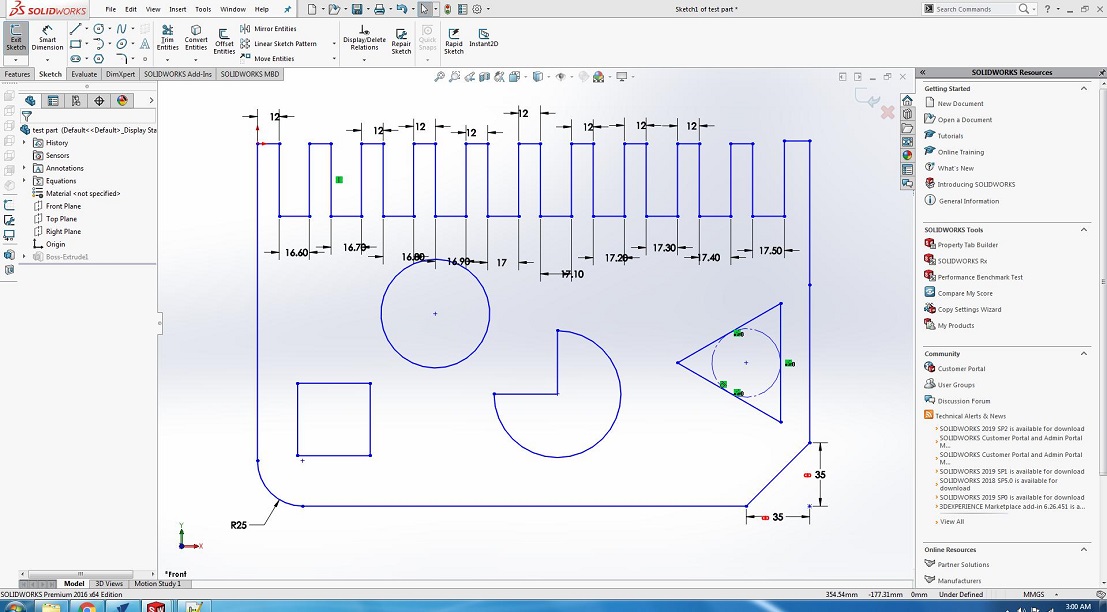
The group assignment of this week is we have to test run out, alignment, speeds, feeds, and toolpaths for your machine. For this we made a design in solid works and cut it in CNC.
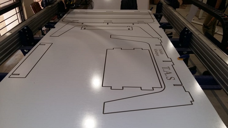
After cutting file on shopbot
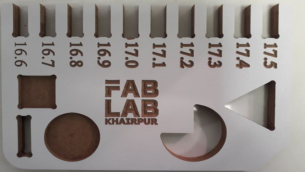
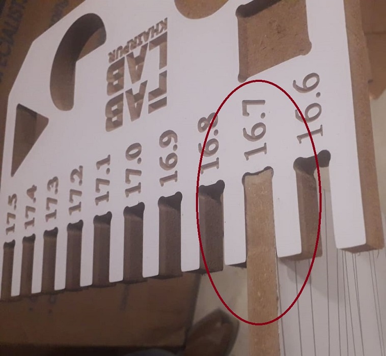
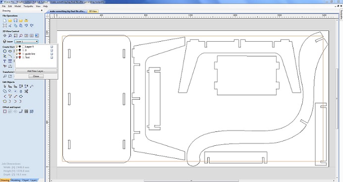
We have the MDF sheets in lab with thickness of 16.3mm. So we cutted part in that sheet, we used both outside cut and inside cut on different areas and also used pocket tool path you can also see in image and after cutting it was fixing in 16.7mm cutted area, we cutted this area with outside cut toolpath.
Individual Assignment
Make Something Big
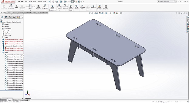
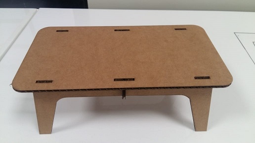
This assignment is all about make something big. So, I decided to make table. I started with different ideas like stool, chair,etc. I finalize the table. I draw rough sketch of table on paper with dimensions. Skteching on the paper is very useful and important for designing. There are very few parts i.e. 5 , uper parts. I will use 16mm MDF for this.
3D Designing
I started with designing parts in solidworks, First I designed top part of table has width, height.
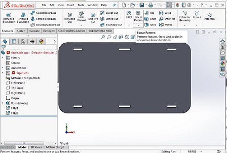
Then I designed leg of table
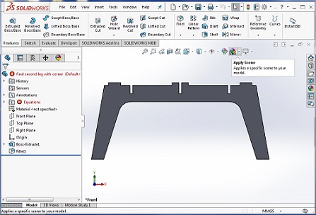
After that I designed supports of table
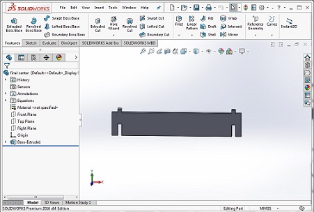
And assemble all parts using "Mate" to check either the parts fitted perfectly or not in Assembly tab.
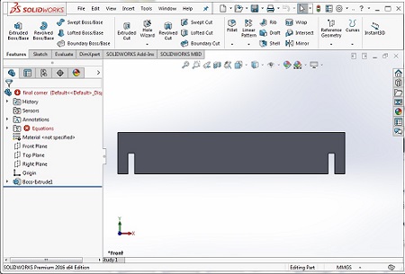
After checking the parts perfectly fitted in assembly I need to make 2D Design for laser cut of it, for 2D Design we open one more assemble tab and set all the parts in front plane
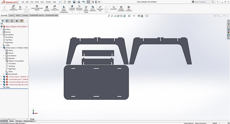
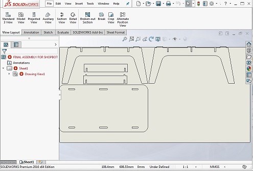
after completing the 2nd assemble document now to open this file in drawing document and save as DXF format for working in InkScape,
The generated DXF file is opened in InkScape and scaled to 25 percent of original size, this can set slit parts to 4mm thick material as we use 4mm cardboard to try a sample for this design. a pdf is generated using same method as we use in first design for laser cutting process in Epilog Laser Cutting machine
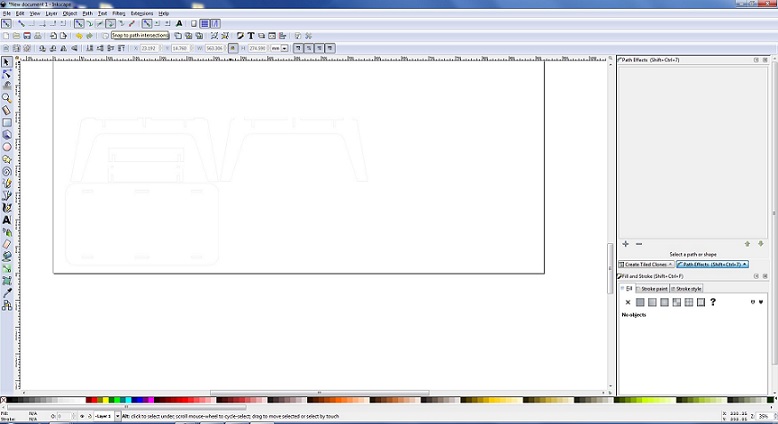
The scaled design on 4mm cardboard is shown below
Software
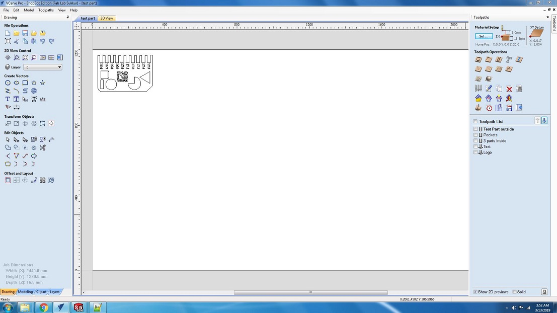
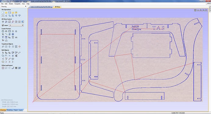
Bofore cutting test part and individual assignment we made some layers in VCarve, which help us to maintain the XY coordinates in case if we stop the machine and some how its coordinates changes. Second the guided layers help us to prevent the machine from accidents.
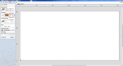
First we set the MDF board size and thickness,16.5mm
Then we make a guide layer to leave space of 50mm from each side and make a border layer to mention boundaries
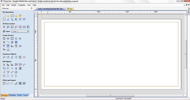
Then we make two more layers one to set text engrave and other is for ouside cuts, to generated toolpaths separately
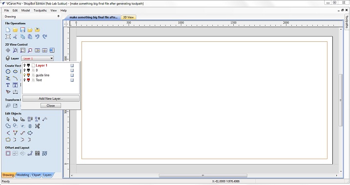
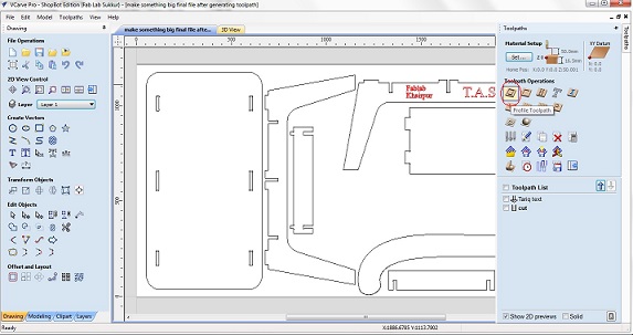
After making layers now I opened my .dxf file of individual assignment in VCarve. I shift all the outside cuts to first layer and engrave text to second layer then rearrange them so they take less space on board
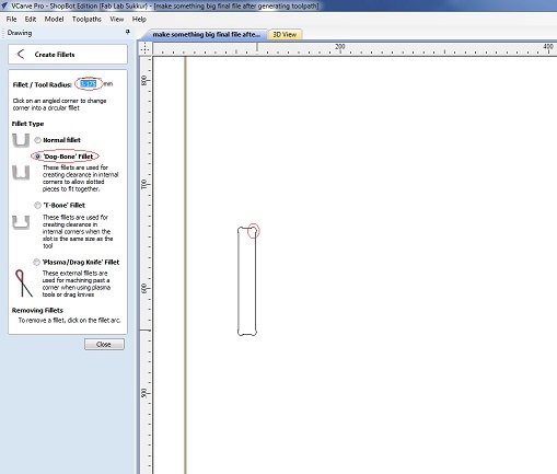
After that i made dog bones on corners with 3.175mm radius
Then I opened test part, and set them in suitable empty space, next step is to generate toolpath now we need to cut the boundaries of the parts so we are using the profile toolpath
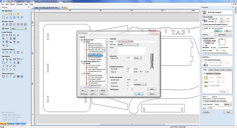
In toolpath settings we set Cut Depth as 17.1mm, Set Machine to run outside vectors, selected 1/4" Down-cut (57-910) drill bit and add tabs which help part to not move from place while cutting.
After that making the toolpath of required parts,The generated toolpaths will be save as .sbp and then .sbp files given to shopbot to perform the job.
CNC milling
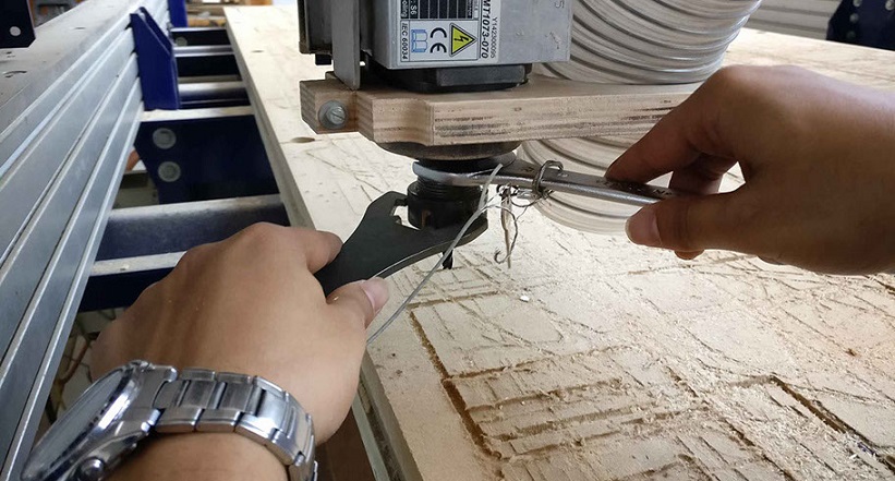
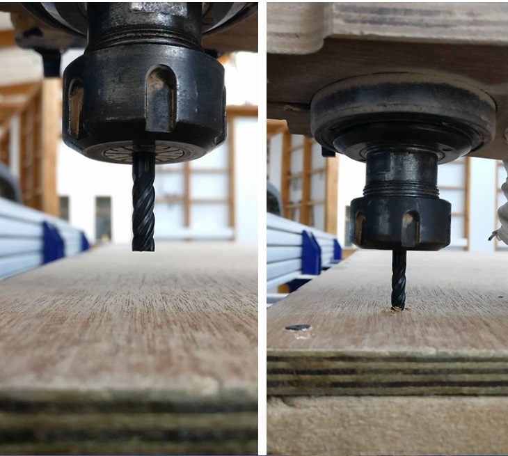
Before starting with the milling process, the first thing that needs to be done is to install the desired milling bit. As mentioned above, the bit has to be installed in the Collet and this is done with the help of these special spanners.
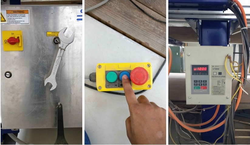
Connect the system with the shopbot software installed using the 2 USB cables provided. On opening the software the axial location of the bit and a command like a screen appears.
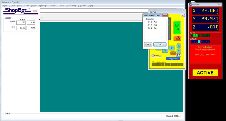
We need to move the drill bit to a point that we consider origin. To do this open the keypad option by clicking the yellow icon in the position menu.
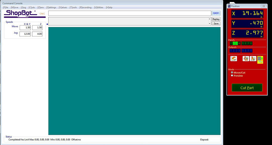
Using the arrow key or the on-screen arrows move the bit to the desired origin point. Setting Z could be slightly tricky. The bit should touch the bed exactly at a point that it scraps the top layer.
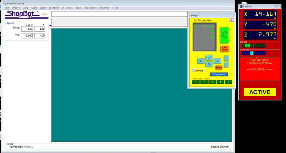
The bit can be moved slowly by clicking on the fixed button. Once the origin is set, click on zero axes and set x,y, and z as zero.
Now its time to import the G-code into the software and this can be done by clicking the cut parts and choosing the GCODE file. Hit start. The code gets loaded up and a message appears to hit the start button in the control box.
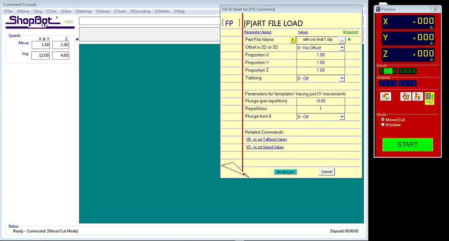
But just before hitting the start button, the exhaust needs to be switched on.
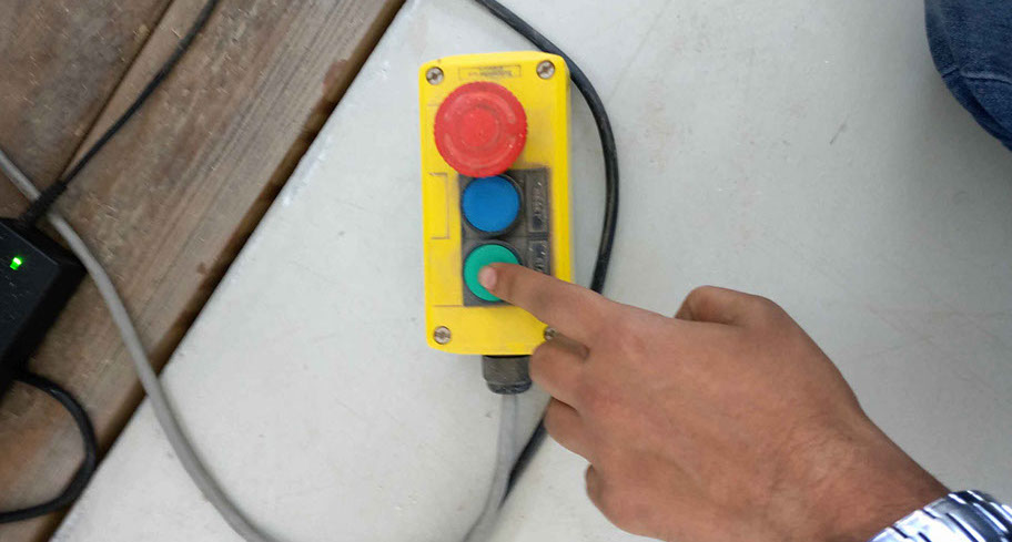
This makes the spindle to rotate and by clicking okay to the message displayed on the screen the cutting process begins.
Assemble the Parts
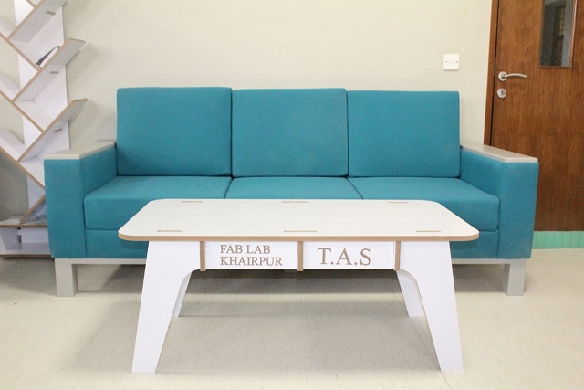
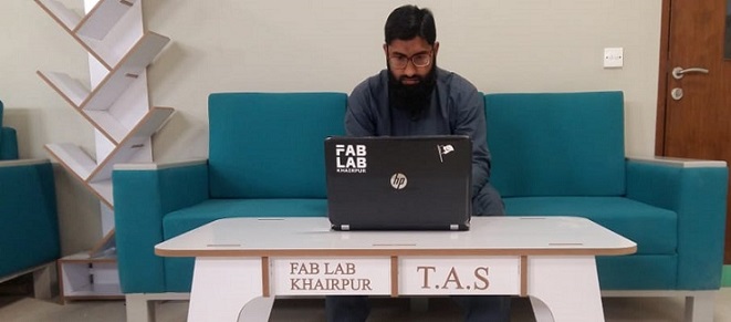
After cutting I assembled the table and its really looking nice and press-fit.....
"Click here"to download all files of this week

Automatic Hot Water Dispenser by Tariq Ahmed Shaikh is licensed under a Creative Commons Attribution-ShareAlike 4.0 International License.
Based on a work at http://fabacademy.org/2019/labs/khairpur/students/tariq-ahmed/