|

| Sukkur IBA University Khairpur Campus Merit, Quality, Excellence |
Week - 5
Electronics Producton
Assignment
Group Assignment
•characterize the specification of your PCB production process
Individual Assignment
•Make an in-circuit programmer by milling the PCB, then optionally trying other processes.
Group Assignment
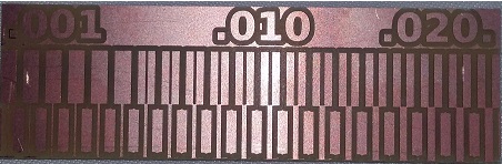
In this week, we have to characterize the specification of PCB production processes and learn how to work CNC milling machine. there are different types of PCB board and we use FR1. For cutting and traces we are using 1/32 and 1/64 drill bit respectively.
PCB Producton
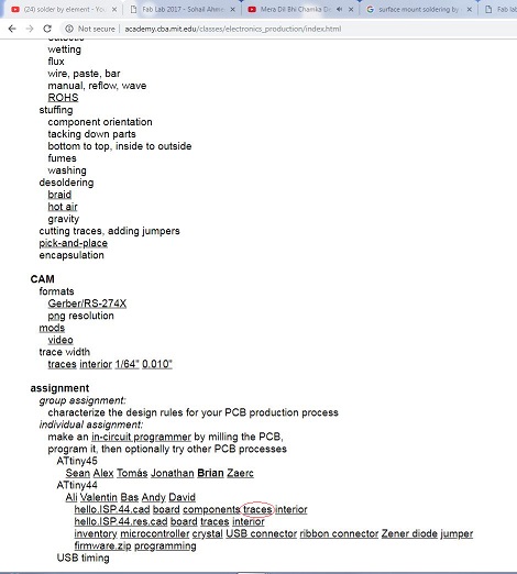
For PCB must use PNGs file and and we download PNG file from Neil's lecture.
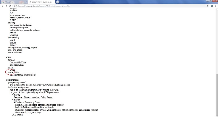
Download Png Files
After download png file we edit in paint for outline
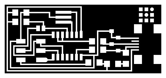
traces file using 1/64 drill bit to trace

outline file using 1/32 drill bit to cut
Fabmodule vs Mod's? pro´s vs con´s
Fab mods have all those options which is provided in fabmodules.org, but I found fabmodules interface easy and user friendly. Fab mods shows the process of generating code for any machines graphically, it seems attractive. But I found fabmodules easy because rather to add a module I can select my option from drop down menu. There was another difference with attracted me to use fabmodules.org because of its simple interface which helps me to focus of my job. Currently I am using and learning fab mods and decide to do future work on it.
Steps for RML File
• First open the www.fabmodules.org for online generating rml file • Click on image(.png) as your input formate file. • Browse and open your desired png fil. • After that, go to output format and select Roland mill(.rml). • Then go to process and select PCB traces 1/64. • At right coner shows output and select SRM-20 machine. • Now set the origions x0=0, y0=0 and z0=0. • Finally click the calculate and save the file.
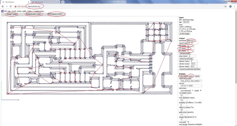
RML trace file
Same steps follows for outline, click on PCB outline 1/32 and click calculate to save the file.
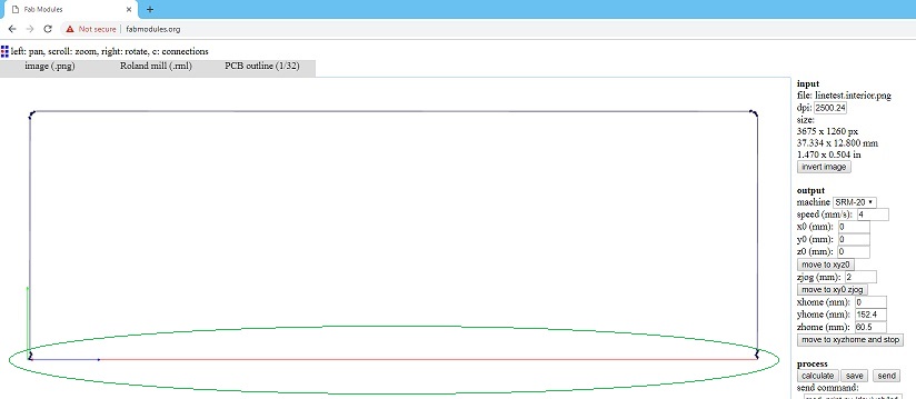
Bottom line of Outlime
while we generate rml file for outline it did not show the bottom line of outline and we told issue to instructor, he says that same problem they already faced, and edited png file again in paint,then we generate outline .rml file.
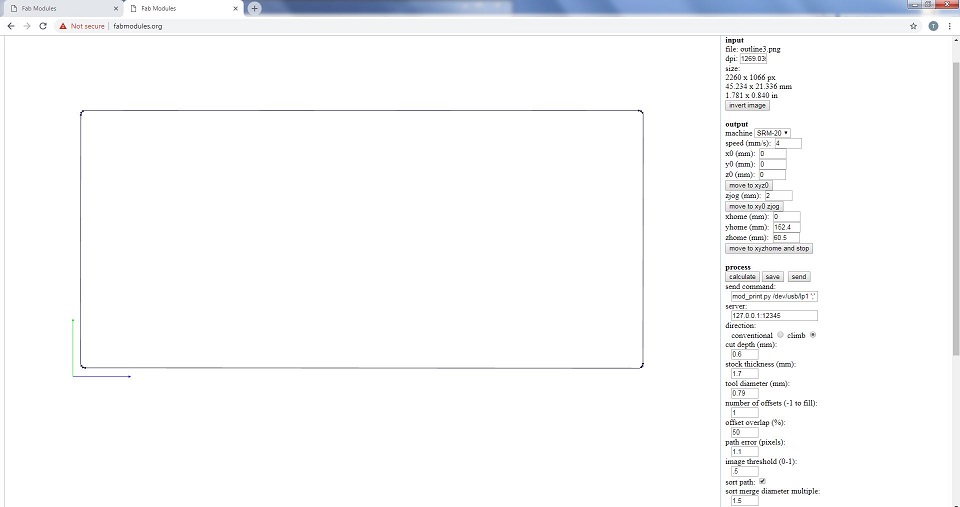
RML Outlime file
After generating RML, sent both files to Rolan monoFAB SRM-20 machine and follow below steps.
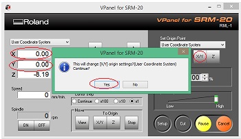
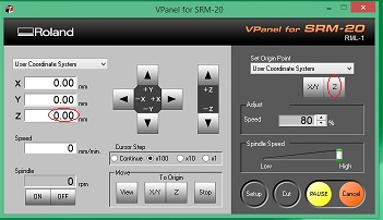
•Place PCB on machine bed. •Open VPanel for SRM-20 in Desktop. •Change the Drill bit for traces 1/64 and cutting 1/32. •Select the origion to x/y and z axis by changing values fo x, y and z axis from where it should be start. •Adjust drill bit until it touches PCB board(It is necessary to touch the board because we have to cut the traces on pcb otherwise the drill bit will rotate in air continuously and won't cut.) •Change Z-axis value little bit to dig PCB board slightly, then select new value of Z-axis as origin.
X/Y origin
Z origin
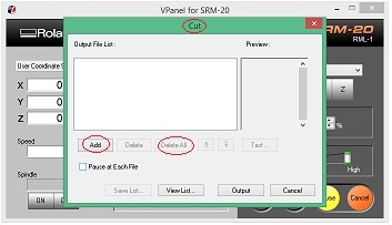
•Click on "Cut" and delete all old files,then add new .rml file which you want to use.
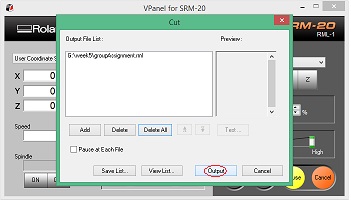
Add RML file
•Click on "Output" to start the process.
Start the Process
We initially made a mistake with resolution while generating rml files.. Ignoring PCB image's default dimensions we changes its dpi/resolution from 5000 to 2000 that resuted increased size of the PCB.
Increased size of PCB
After that we generate again .rml file using above method.
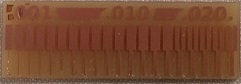
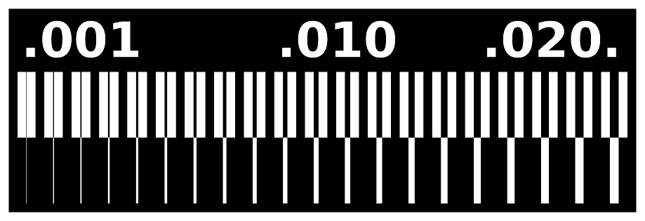
Here is Final result
The group assignment shows that how much machine works precisely with 1/64 drill bit to show even 0.001 in.
Individual Assignment
•In individual assignment, make an in-circuit programmer by milling the PCB.
•And Uploading program in the board.My chioce : FABisp
As i was new in this area so i choose fabisp board, this board is easy as compared to other programming boards. further more the other available options were tried by my group mates which didn't worked.
PCB Making
For PCB must use PNGs file and and i download PNG file from Neil's lecture.
Files in red Circle
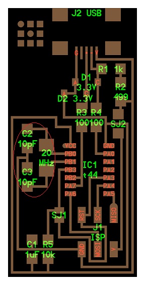
Here is traces file.
Here is outline file.
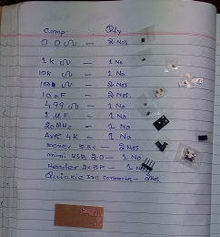
I used same steps for PCB as above mentioned.I enlist all the components which i need to make a PCB board.
List of components
I solder almost all components when i was solder 10pF capacitor and 20 MHz Standard Clock Oscillators there is no any place for both components in the board, then i asked to instructor how i place the capacitors and oscillator, he said that you take components of other board and you solder an other board.
Capacitor and Oscillator
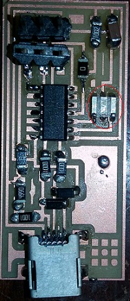
After that i solder resonator component inplace of capacitor and oscillators.
Resonator Component(in circle)
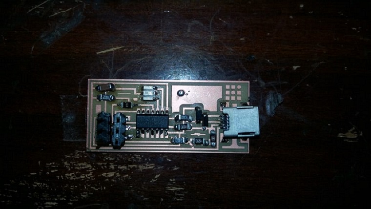
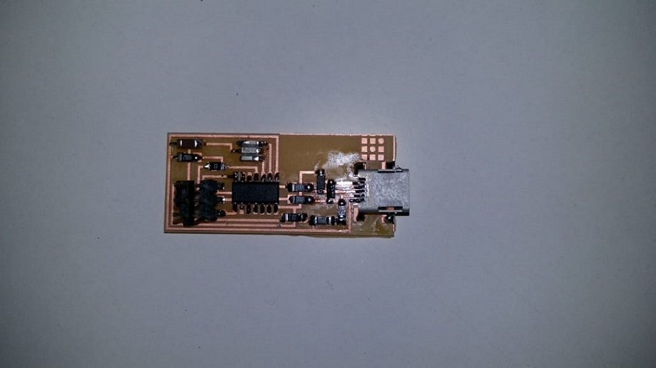
Initially I found the fabisp suggested by Neil in fab academy 2019 lecture. I tried that one . I followed all steps upto soldering so when I started the programming it gave me some errors "fuse failed", it took my 1 day so I decide to reprint the fab isp. This time I did every step carefully that's why I got the actual results which I wanted. In below given pictures my fab Isp is shown.
This is my First PCB board
This is my Second PCB board
It is my first experience for making PCB and soldering of components.
FabISP Programming
Following steps were required for the programming of ISP:
I used Ubuntu Operating System for the programming purpose. Following steps were required for the programming of ISP :
- Installing the necessary softwares for AVR Programming.
- Avrdude (for programming AVR microcontrollers)
- GCC (to compile C code)
- Open the termianl and type following commands:
- sudo apt-get install flex byacc bison gcc libusb-dev avrdude
Then type
- sudo apt-get install gcc-avr
- type "y" when asked to do so by your system
- sudo apt-get install avr-libc
Then type (may already be installed):
- sudo apt-get install libc6-dev
Download and Unzip the Firmware:
Move to the desktop
- cd ~/Desktop
Download the firmware from the Fab Academy Electronics Production page.
- wget http://academy.cba.mit.edu/classes/embedded_programming/firmware.zip
Unzip the firmware
- unzip firmware.zip
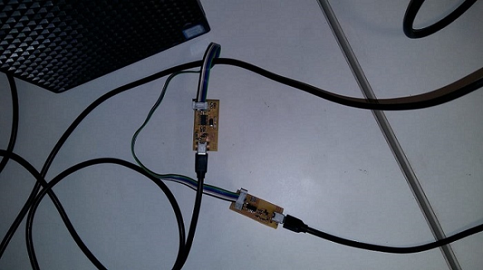
- Power the FabISP Board:
- Pulg in the mini USB connector of your FABISP into computer.
- Make sure you have plugged in another working FabISP in to the 6-pin programming header.
Program the Board
- Program the FabISP by writing following commands in Terminal step by step:
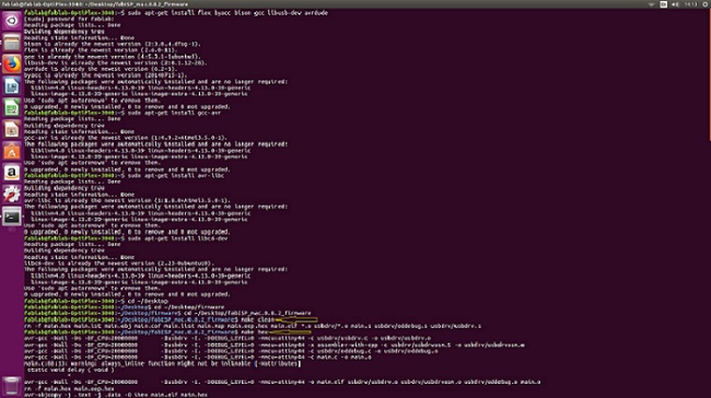
- make clean
- Make HEX
"make clean" and "make hex commands"
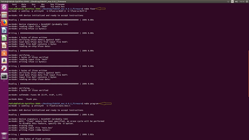
- Make Fuse
- Make program
"make fuse" and "make program commands"
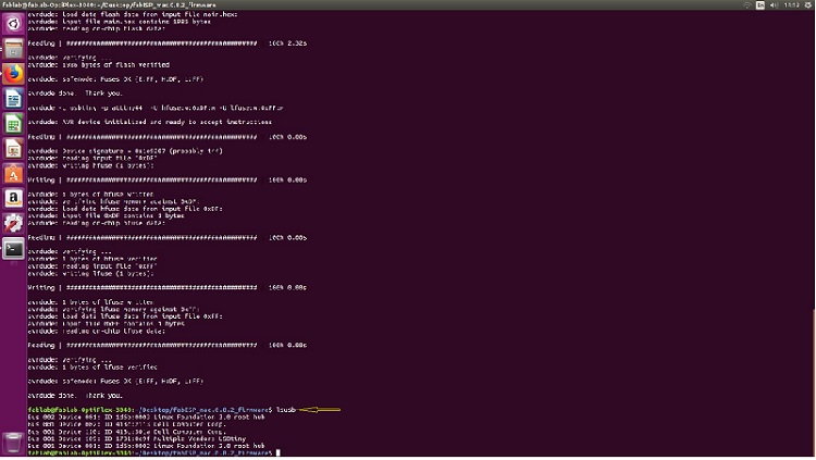
- Now. Verify that your ISP is working fine by tyoing the following command in terminal.
- lsusb
- The verification is performed.
"lsusb command"
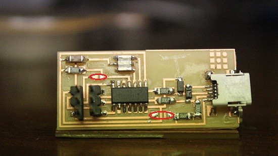
- Removing the Jumpers (0 ohm) resistors:
"Zero resistors"
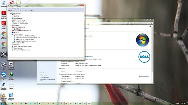
- Last step: Installing the Drivers
- Download the drivers
- Plug in the programmer into computer , then open the Device manager.
"USBtiny"
"Click here"to download all files of this week
« Week4 Week6 »
Automatic Hot Water Dispenser by Tariq Ahmed Shaikh is licensed under a Creative Commons Attribution-ShareAlike 4.0 International License.
Based on a work at http://fabacademy.org/2019/labs/khairpur/students/tariq-ahmed/