Week - 11
Input Devices
Assignment
Group Assignment
• probe an input device's analog levels and digital signals
Individual Assignment
• measure something: add a sensor to a microcontroller board that you have designed and read it
Group Assignment
This week's group assignment was to detect the analogue and digital levels of input device we made individually so we started to measure the anlogue voltage levels of photo transitor which was used by me in this week's assignment. In group assignment we measured the voltage levels of this component which changes whenever we increase or decrease the intensity of lights on it. We connected the sensor module to 5 voltage and checked the output on data pin and ground using multimeter. We observed that whenever we increase the intensity of light voltages increase and whenever we decrease intensity of light voltage decrease. Both of the experiments are shown below in figures (a) and (b) respectively.

(a) Measuring Voltage levels with low intensity of light

(b) Measuring Voltage levels with high intensity of light
HC SR-04 Ultrasonic sensor is used by one of our group member in his individual task of this week so we used that sensor for detecting the digital signals. We have detected the change in digital signal in Oscilloscope using arduino Leonardo. A sensor is connected with arduino and the pin of Echo is connected with Oscilloscope. Arduino Leonardo is programmed to detect obstacle in front of Ultrasonic sensor, when an obstacle is present in front of Ultrasonic sensor we found change in wave in oscilloscope. The captured digital signal of ultrasonic sensor is shown below in figure. Furthermore the echo pin of sensor is connected to the pin 13 of leonardo which is also connected to led of board. The video given below shows that whenever there is change in signal led is blinking. The rate of led blink is very fast because digital signal is changing fastly.

Digital signal shown in Oscilloscope
Individual Assignment
An input device sends information to a computer system for processing. This week we had to use sensors to measure something as an input device. A sensor is a device that detects and responds to some type of input from the physical environment. The specific input could be light, heat, motion, moisture, pressure, or any one of a great number of other environmental phenomena.
Hellow distance board
I redraw this board from hello distance board which is available in Input Devices lecture. The board is based on attiny45 controller with connected HC-SR04 sensor.
List of Components:
- 1x ATtiny45
- 1x 10kΩ Resistor
- 1x 1uF Capacitor
- 1x FTDI Header
- 1x 6 pin AVRISP Header
- 1x 4 pin Header
PCB Designing
For PCB designing I worked on Eagle 7.5 (an introduction of this software is mentioned in Electronic Design Week). First I made a schematic:

Distance Sensor Schematic
After that I generate PCB board and route it.

PCB Design
Generating .RML Files
For generating RML files, first I need my PCB design in .png format for that I export my PCB design in .png while resolution kept 2000 dpi and Monochrome

file exporting in .png format

keeping 2000 dpi resolution & monochrome
when png file was generated, open it in paint for making traces, outline and drills file of PCB.
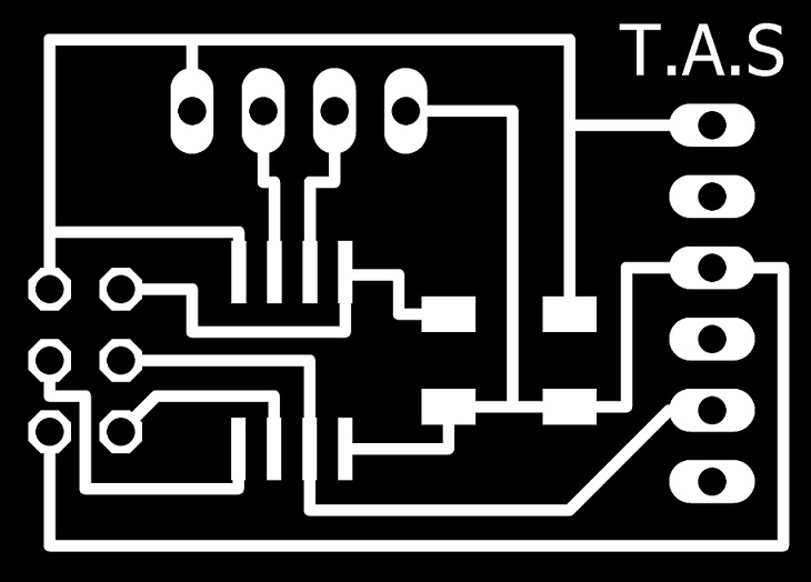
PCB traces

PCB outline
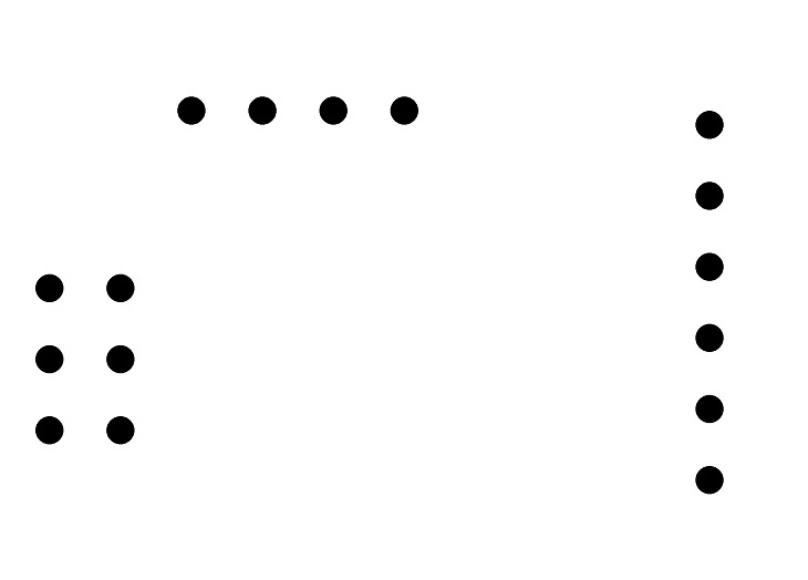
PCB drills
after making traces, outline and drills file of a pcb I used fabmodules to generate RML files, all important settings are mentioned in a pictures below, for detailed fabmodules settings visit Electronics Production Week
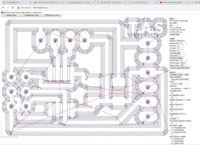
generating .rml file of PCB traces
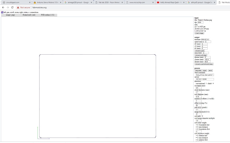
generating .rml file of PCB outline
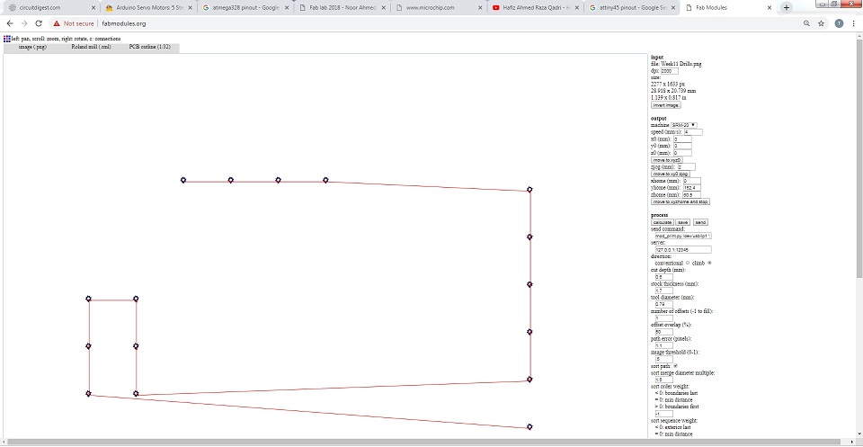
generating .rml file of PCB drills
Milling and Soldering
.rml files are given to Roland SRM-20 Milling Machine. For traces 1/64 drill bit, for outline and drills we are using 1/32 drill bit

Printed Circuit Board

Soldered Components on a board
Programming the board
To program a board I need an ISP programmer, I made one developer board in Electronics Production Week so I used it with my distance sensing board.
I am using Arduino IDE for programming my board. For setting up Arduino IDE to work with FabISP I mentioned in detail in Embedded Programming Week. I programmed my board with Neil's hello.HC-SR04.c code because it supports Neil's Python code (Python is new for me, in next board I did some changes in my board and code). Before programming the board first it is required to burn bootloader in it.
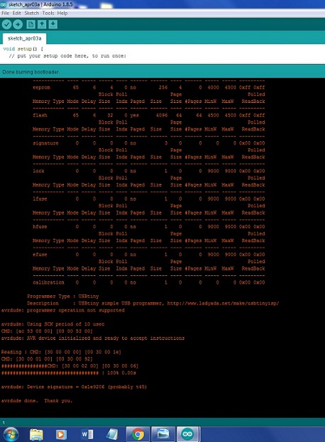
Done burning bootloader
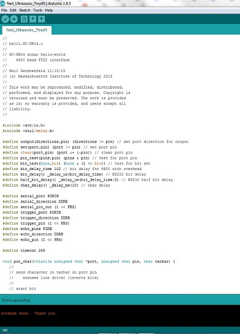
Done uploading
Now to see the results on serial monitor first I installed Python 3.6.5

Downloading Python
I just copy paste the Neil's code in python but it didn't work. and got some errors.After little bit search on internet I understands that the errors are because of python version, so I make some changes I just change Tkinter to tkinter apply parenthesis where missing and install numpy and serial modules.

Python code uploading

successfully Run window
I am using command prompt to run the python.Below I mention steps how to work on python using command prompt
First check either Python is present in path or not

if Python is not show in command prompt then go to System properties by clicking on Start > right click on computer and select Properties > click on Advanced system settings and select Environment Variables. Save the python Address in path window in Environment variables

Numpy library not available: after alot of sifting through related pages I found that numpy package can be installed through pip script which is available in C:\Users\Preferred Customer\AppData\Local\Programs\Python\Python36\Scripts>

Now I run the command in command prompt python Ultra.py 4 it says run python file and get data from com4

Here are the results of Distance sensor which is received via FTDI Cable
"Click here"to download all files of this week

Automatic Hot Water Dispenser by Tariq Ahmed Shaikh is licensed under a Creative Commons Attribution-ShareAlike 4.0 International License.
Based on a work at http://fabacademy.org/2019/labs/khairpur/students/tariq-ahmed/

