Group Assignment: Use the test equipment (digital voltmeter, oscilloscope, regulated power supply) in your lab to observe the operation of a microcontroller circuit board
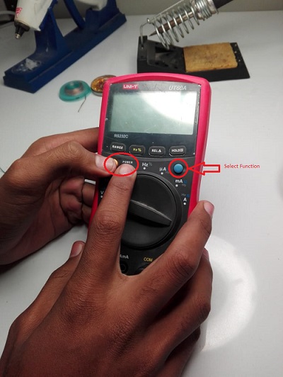
Below we can see all three test equipments mentioned above.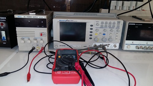 As a group assigment this week we were asked to use test equipment and test our microcontroller circuit board. As i am an electronics engineer so i already have worked with these equipments, still i started with the basic as this being a group assignment was ment for people (from other background like mechanical and cs etc..) earn some familarity with electronics tool. We actually started by testing resitance of a resitor as shown below. Its very simple. All you need to do is to switch on the Digital Multmeter/Voltmeter with yellow button and select what quantity you want to measure using blue button shown.
Below you see the digital multimeter. With one power button and one select/control button. To measure any quantity you need to stear the central handle to quantity group and switch/select to measure a particular quantity.
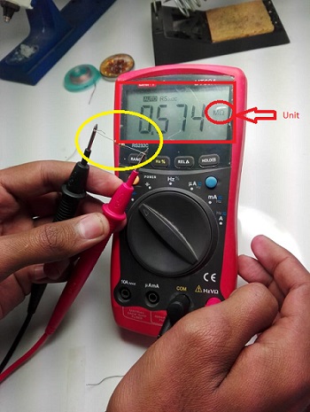
 Now Let's measure resistance. To do so just connect two nobes of multimeter(red and black) on both terminals of resistor as shown and select resistance. Below screen shows the value in mega ohms as 0.5m ohms that will be 500Kohm.
 Now let's understand power supply. It's core purpose is to supply standared voltage/current that could be varied from control section shown.
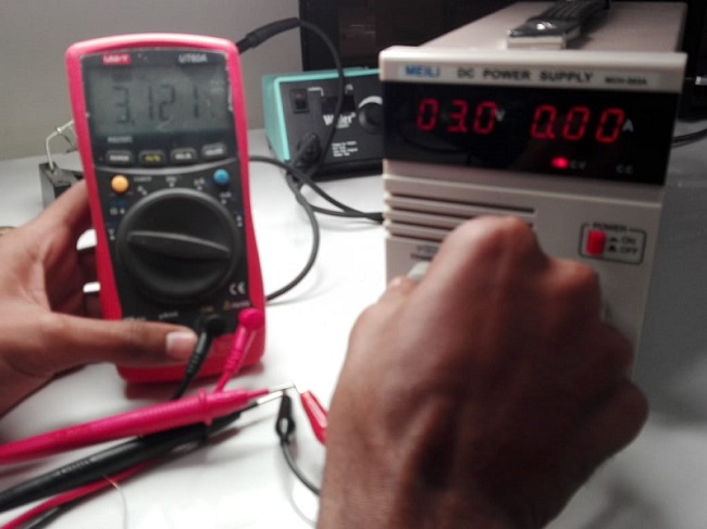
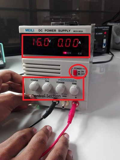 Now let's measure voltage. Notice the central handle and unit that is V. That means we are measuring voltage. First we supplied 3 voltages and measured it on multimeter/voltmeter as following.
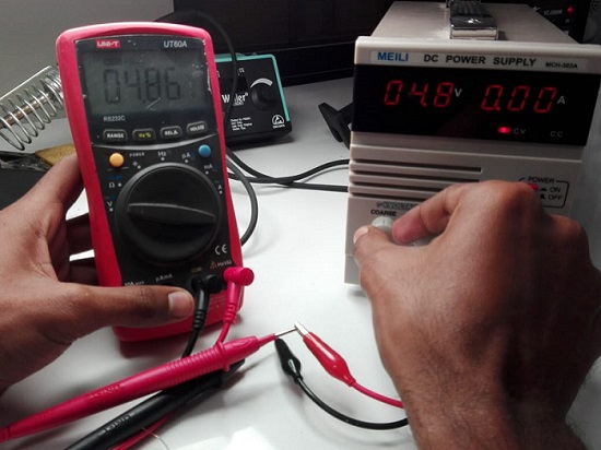
 Next we actually varied supply voltage and made it 4.8. So we get following results.
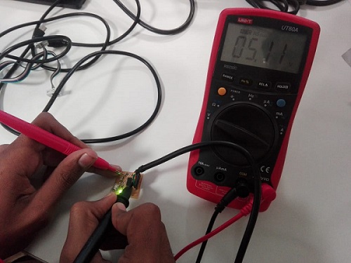
 In the end of multimeter testing we also tested our boards with voltmeter/multimeter by checking if it is receiving control voltage (Vcc) or not.
 Below you can see oscilloscope. We did not do much but just tested its operation as following.
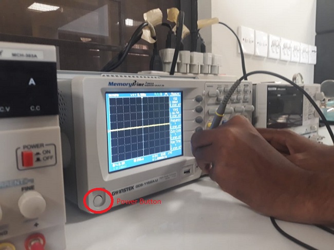 To test the oscilloscope first just connect the probe of connected channel back in oscilloscope and you will get this if all is ok.
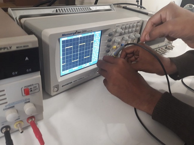 Testing two of the channels available in oscilloscope.
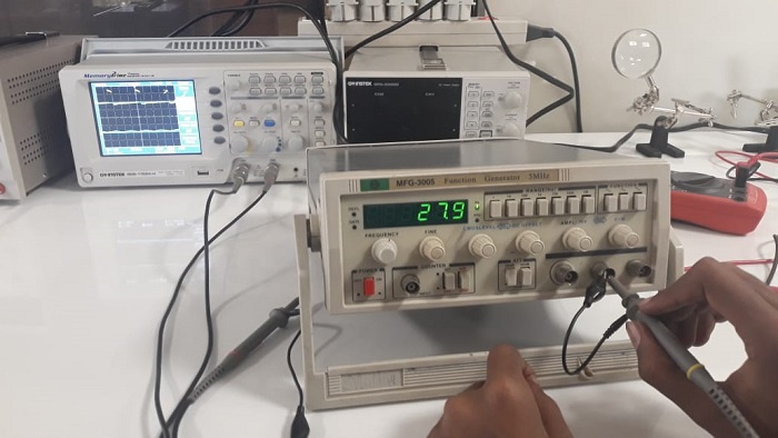
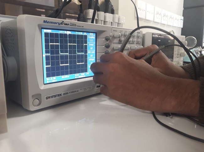 Now just verifying supply signal into oscilloscope in the end.
Individual Assignment: Redraw this board, add (at least) a button and LED (with current-limiting resistor) check the design rules, make it, and test it
This week i started with redrawing atinny44 board. To do so the first and primary thing required is schematic. Schematic is a symbolic and simplified diagram representation in electronics. I already have worked on eagle software so i chose to continue using it as i consider it very easy to use and also to understand. Opening the platform. You then see a window like this.. go to file > new > Schematic
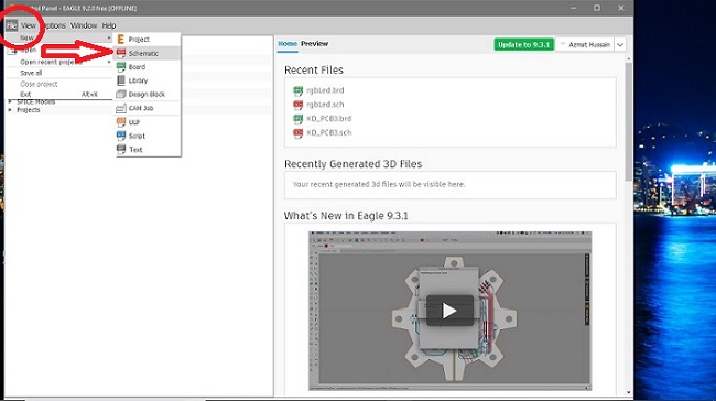 Now you have this clear window to start your schematic.
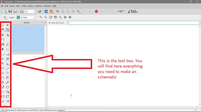 So let's start.. In softwares like eagle package of the device.component in use matters as we need to use the package that is available to us physically. In fab lab most of the components are of standered package from fab. fab is a component library with packages available in fab labs. So we first need to add/install/import fab library into eagle. Download fab library and paste it in lbr/library folder > eagle folder > c disk. So click on add part and blue highlighted window will pop up.
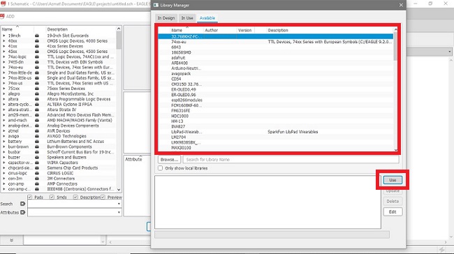
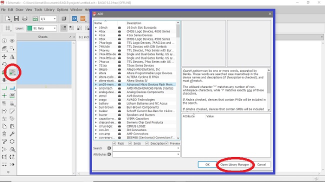 Now after clicking on open library manger. We get into library manager that looks like following..
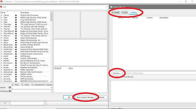 Here simply select all and click on use..
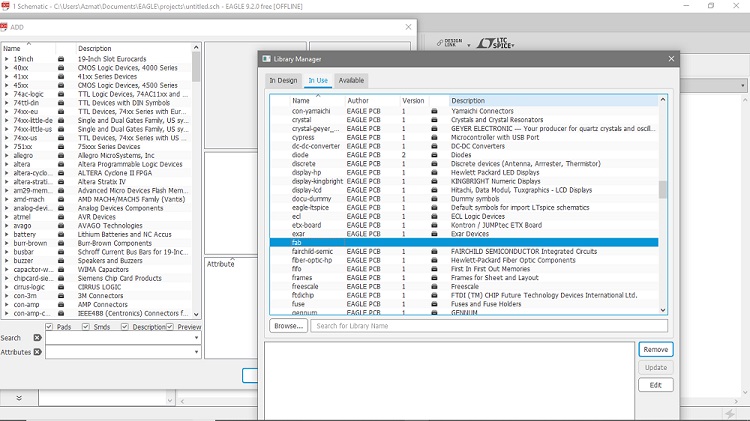
 After this we just go to "in use" window and see if we have our fab library there..
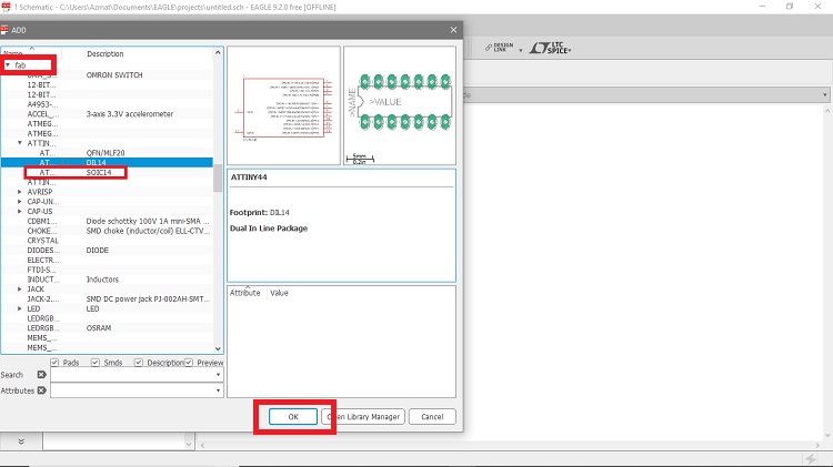
 Now go back and click on ADD PART and import the components you want to as following..
Note: Make sure you have list of components with you that are required!
Once you clicked ok after selecting a particular device and its hardware package, you will have it imported to your schematic window. Move it, rotate it, and do whatever you want to do with it.
 I then just kept on repeating previous step and kept importing devices as per my list of components and that is it, I have all my components imported to my working area/schematic window.
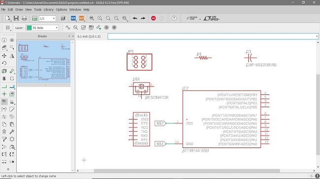 Once i am here. Now lets make connections. I chhose very simpe way to do so and that is by labelling individual branches > checkout.
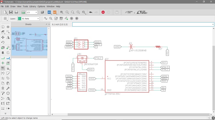
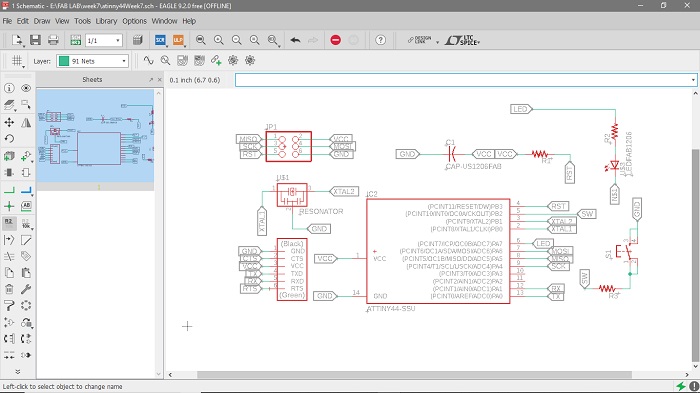
My schematic look alike following once it was done.. By now i have attavhed label to every branch i will use. Also i have named atinny44 all branches in use possibly!
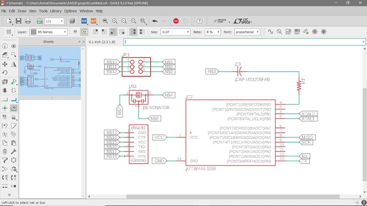 Now select name tool and name the branch as same it is to be connected with..
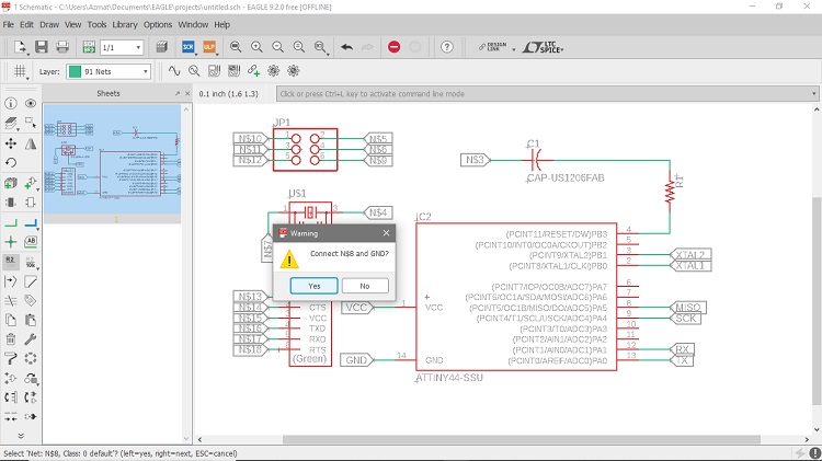 Repeat the name tool step for all branches in use..
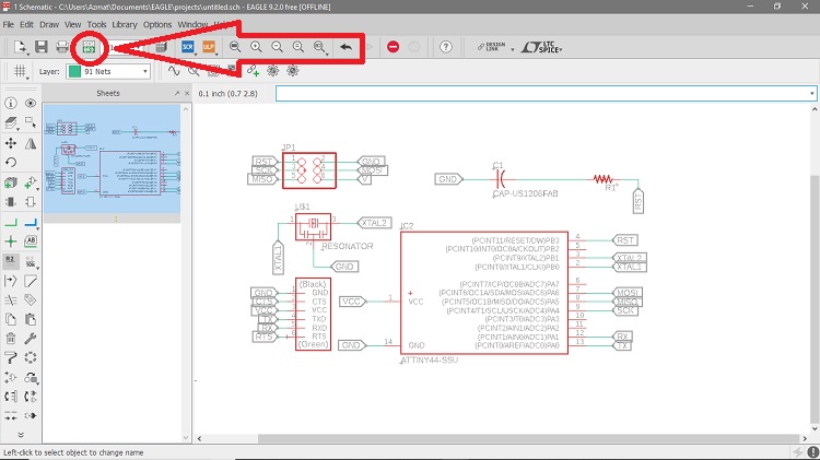
 Now it is time for routing.. Lets open up to it. Click on below highlighted icon (For EAGLE9.2.0 and advanced) and you will have a new window popping up as shown.
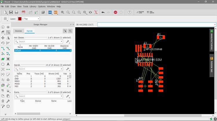 Here again you have all the same tools as for schematic except few. Like here you cant make a connection so there is no net here.. Rather here you will make traces for current to flow so here there is route tool to do so..
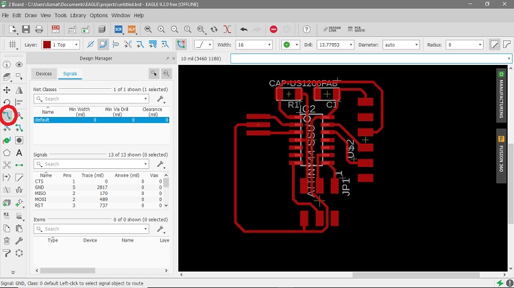
Let's start. I did route it using below highlighted tool route. Note: You can set orientation of your components using move, rotate, etc commands
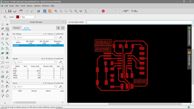
 Next we had to modify the design by adding an LED and a switch so here we go.
 Below is modified and final routing.
 Next is not something new.. Now we need to generate rml files from fab modules which is as following. you can follow it step by step in week4.
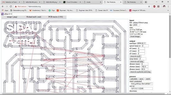 Below is the atinny44 board i designed. I first fabrictaed it > soldered it and that is it. Fabriction steps are explained in week4.
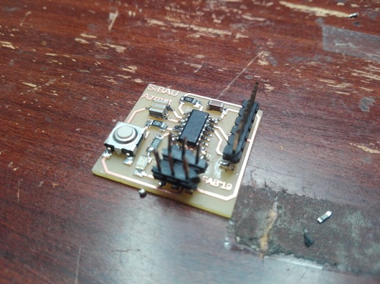 We already have tested it in group assignment part..
Click here to get design files.. Mill/Test your board and enjoy!

This work is licensed under a Creative Commons Attribution-ShareAlike 4.0 International License
Copyright © 2019 Azmat Hussain