Group Assignment:
This week group assignment was more of the same as what we did in laser cutting week because in this week also we had to measure the kerf but this time it was of the tool rather than laser. Follwoing attached picture is a very compact and basic example to test the kerf with pocketing and cutting on shopbot. We can see different size female-teeths, and the one that fits in perfectly with male-teeth would give us the error margin. In this figure also we tested engraving tool and did pocketing also as shown.
Individual Assignment: Make something big!
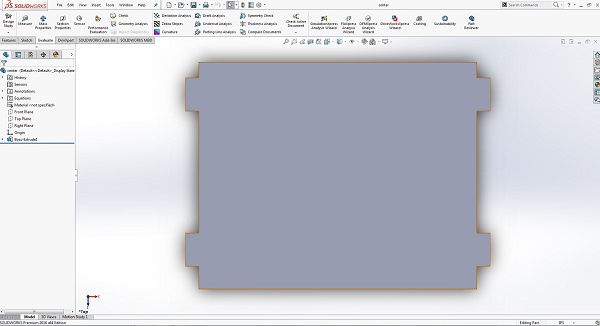
Idea of this assignment was to use shopbot primarily to cut a parametric press fit kit. To do so i had many ideas but none qualified for cutting so after searching for 3 long days i found this idea of making a podium from fab academy previous student. I sketched all of the following designs out of simple rectangles with average dimensions from google. I sketched main part of my design and that was side part.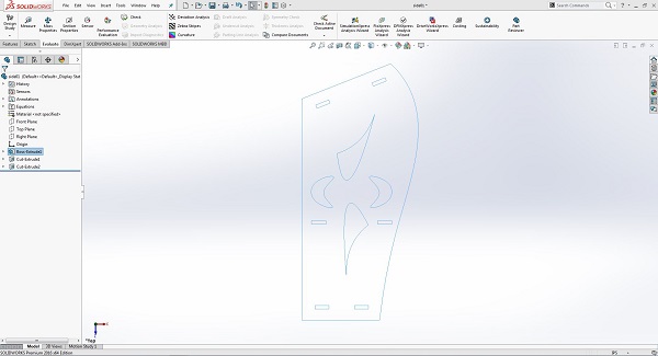
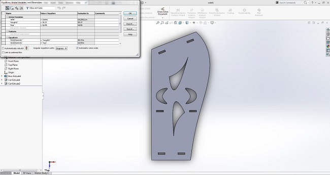 Next i continued making other parts like top, center and bottom as following. First i sketched and made following part as top of the podium.
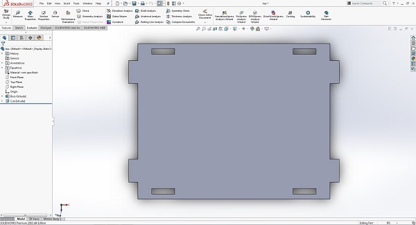 Just to make it more relavent i also added small boundaries to hold stuff.
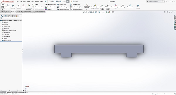 Then i designed bottom and center respectively as shown below.

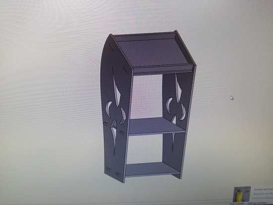
 Now it was time for assembly and i just kept admiring it once it came together as follows.
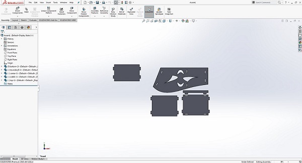
 To cut evrything i made another assembly with top view of every part placed side by side.
 After assembly i had to get a .dxf file that could be worked again in Vcarve. For that i made assembly drawing in solidworks as following.
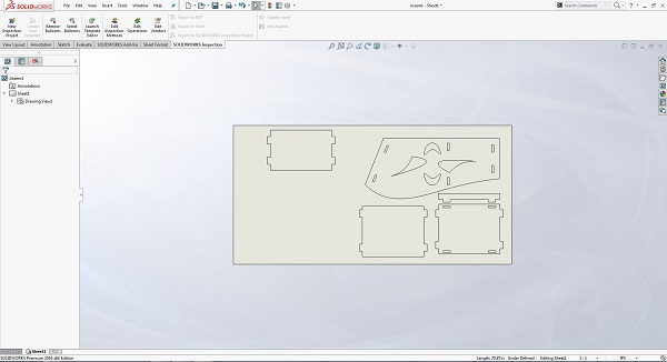 Save the above file as dxf. Now first we made test cut on lser cut. We already have discussed operation of laser cutter in week 3. So only assembly qualified for the website.
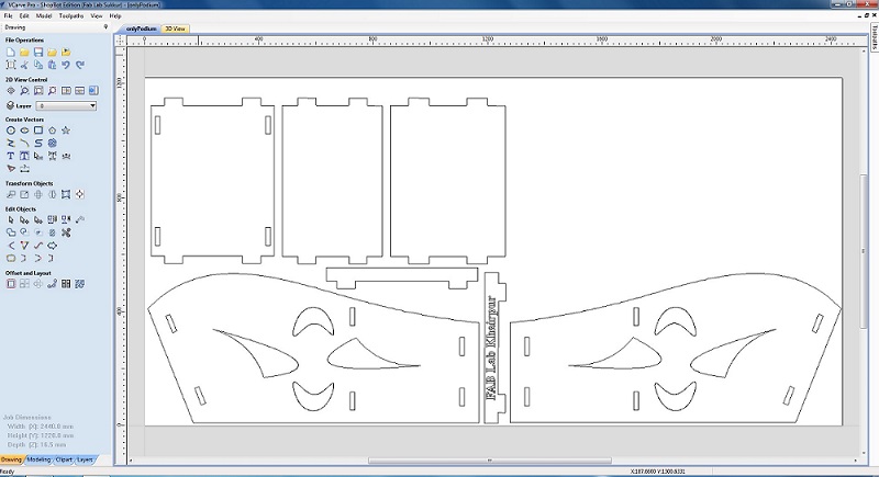
 open Vcarve. Here first thing is to adjust the parts and make copies if needed using tool bar on the left side. I simply used move, rotate, copy-paste, etc tools to get following adjustment for an 4x8 sheet.
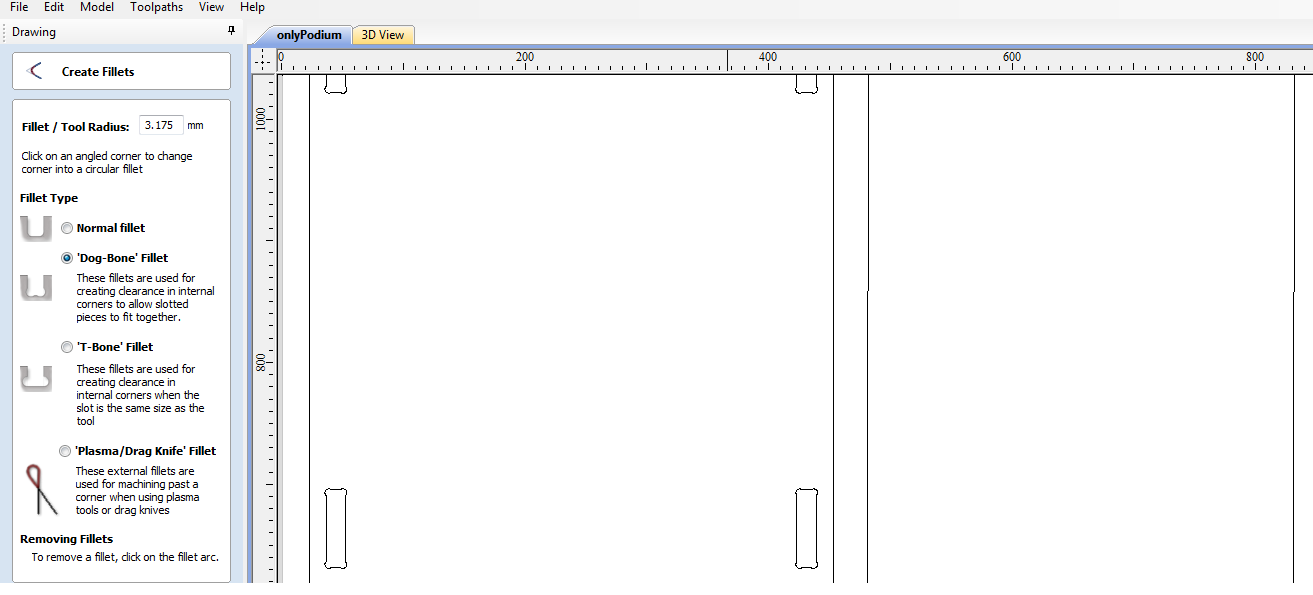
 Next we make the dog bones as shown.
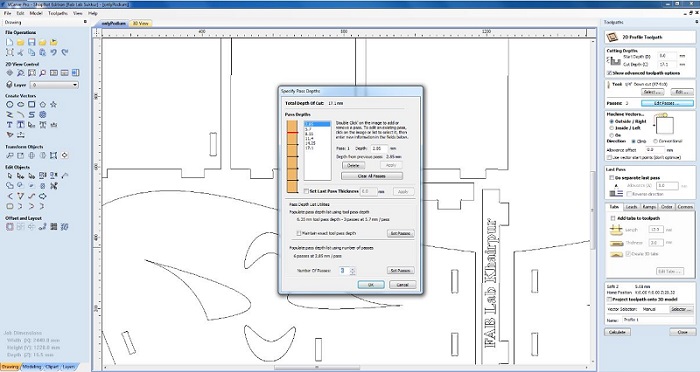
 Now let's generate toolpaths..
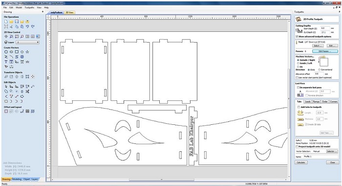 We need to specify the passes. Passes means number of turns machine should take to cut the part. To define passess we will devide our material thickness to the thickness per pass/turn, (e.g we need 3mm per pass/turn) so 18mm/3mm will let machine to take 6 turns to cut our design.
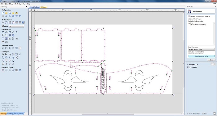
 Next we will generate three different toolpath files, first outside cut toolpath file in which machine will cut outside the design dimensions.
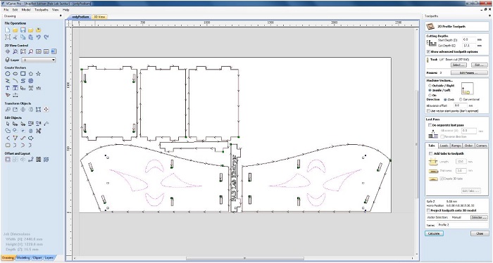
 Then we will also generate inside cut toolpath, i only cutted the design on podium using this toolpath.
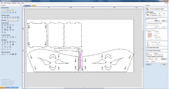
 Text engraving was done separattely as shown.
 Then i added possible tabs so that while cutting part dont come out because of the pressure applied by machine.
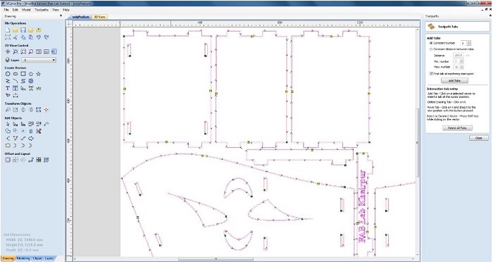 and finally we have a 3d view as following.
 Extra Tips: Dog-bones are created to make our design fit more solid. Where as we should add tabs where needed just to make sure that our part sticks in the board while machine is operating. Once machine cuts a part it is separated from the sheet, hence it starts moving with viberation/force applied by machine onto the sheet.
With toolspath files saved, let's go to machine!
Next, it was all about cutting, assembling..
Extra Tips: Dog-bones are created to make our design fit more solid. Where as we should add tabs where needed just to make sure that our part sticks in the board while machine is operating. Once machine cuts a part it is separated from the sheet, hence it starts moving with viberation/force applied by machine onto the sheet.
With toolspath files saved, let's go to machine!
Next, it was all about cutting, assembling..
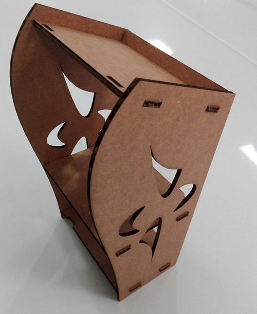
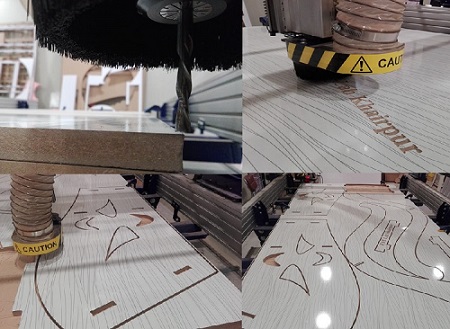 and Nothing more.. We have our podium ready.
 Click here to get design files.. Cut/assemble the podium and enjoy!

This work is licensed under a Creative Commons Attribution-ShareAlike 4.0 International License
Copyright © 2019 Azmat Hussain