Group Assignment: Measure the power consumption of an output device
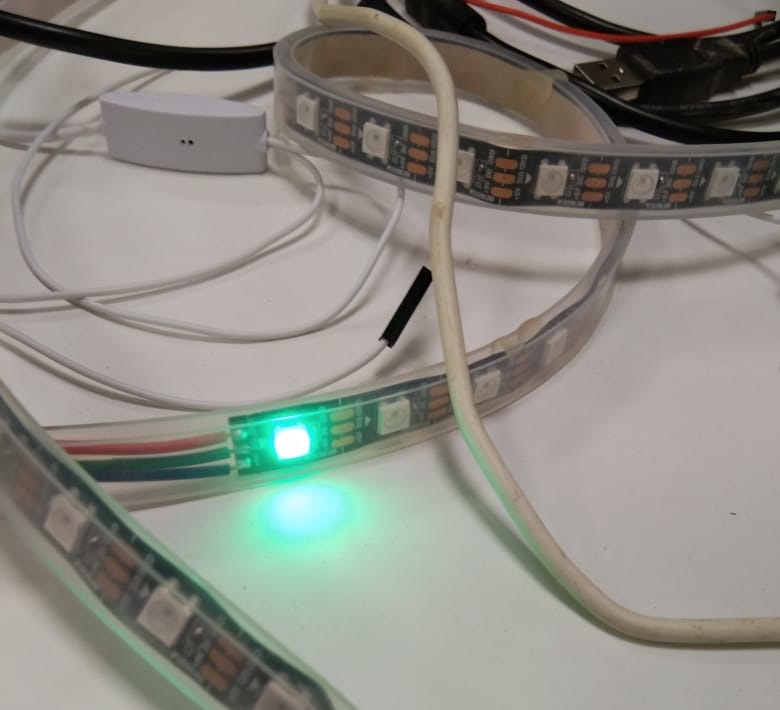
In this week group assignment we have to measure power consumptions of an output device. We used did do with RGB LEDs, we measured power consumptions of an individul led in strip.First we measured voltage and as expected it is approximately 5V.
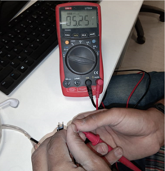 Next as we need power so from P=VI, we need I to find P. Hence we measured current as.
 So with I=approximately 47Amp, and voltage being 5V. We get power as P = 5*47 = 235Watts
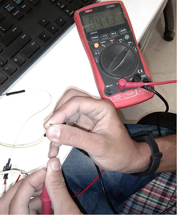
Also as rgb leds have different different current rating for different colors because of different intensity. Red led drains more current as compared to blue and green so above we we checked for red. Let's see for green as it will be same for blue.
 Here is the current in amps
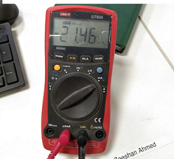 So with 5V being constant supply current has varied for green led as green and blue are relatively less intense compared to red.
hence power here will be P = VI = 5*21 = 107Watts
So with 5V being constant supply current has varied for green led as green and blue are relatively less intense compared to red.
hence power here will be P = VI = 5*21 = 107Watts
Individual Assignment: Add an output device to a microcontroller board you've designed, and program it to do something
This week as a group assignment we need to use an output device.Below shown is my general purpose board that i made in embeded programming week and i have been using it since then for most of my electronic assignments. Will also use it here..
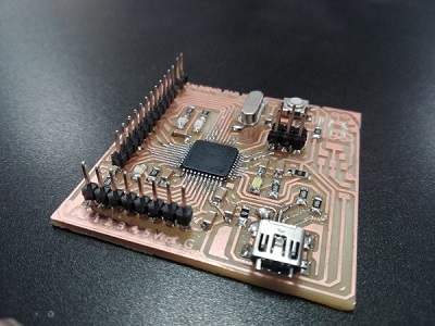 For this week i tried to operate an output device that i will be using in my final project and that is dc water pump. I made a PCB to drive the dc motor using pwm. In this pcb i simply used an NMOS to control the flow of current, hence water. What happens with NMOS (the n-channel mosfet) that it can act as a switch. Following image might help you understand an nmos as a switch.
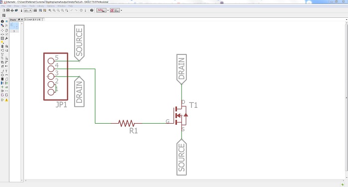
 Hence as shown the input/gate will be connected to pwm pin where as we connect load at one terminal (drain) and supply at the other (gate) to control the flow of current and hence the speed of motor and directly or indirectly flow of water.
Below shown is the schematic to serve our purpose.
Hence as shown the input/gate will be connected to pwm pin where as we connect load at one terminal (drain) and supply at the other (gate) to control the flow of current and hence the speed of motor and directly or indirectly flow of water.
Below shown is the schematic to serve our purpose.
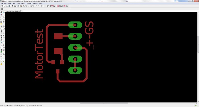
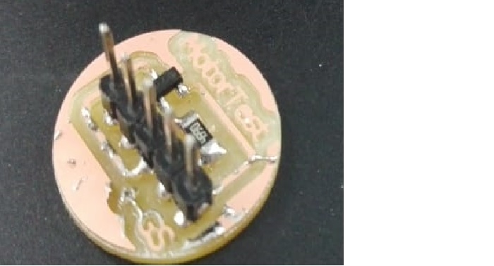
 and this is board visual of the board with an NMOS having a limiting resistor at gate of the
 Then generated rml files from fabmodules.org, Machined them.. soldered them as we have learned in electronic design weeks.
 Next is to program Leonardo board, let's go do that.. OPEN ARDUINO IDE you can find following code (.ino file) at the end of the page
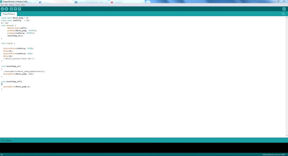 Just click on upload button and that is it.. look for the video.
Please follow this video to see the board working.
Click here to get design files.. Enjoy with sucessfull outputs!
Just click on upload button and that is it.. look for the video.
Please follow this video to see the board working.
Click here to get design files.. Enjoy with sucessfull outputs!

This work is licensed under a Creative Commons Attribution-ShareAlike 4.0 International License
Copyright © 2019 Azmat Hussain