Group Assignment: Probe an input device's analog levels and digital signals
This week's group assignment was to detect the analogue and digital levels of input device we made individually so we started to measure the anlogue voltage levels of photo transitor which was used by me in this week's assignment. In group assignment we measured the voltage levels of this component which changes whenever we increase or decrease the intensity of lights on it. We connected the sensor module to 5 voltage and checked the output on data pin and ground using multimeter. We observed that whenever we increase the intensity of light voltages increase and whenever we decrease intensity of light voltage decrease. Both of the experiments are shown below in figures (a) and (b) respectively.
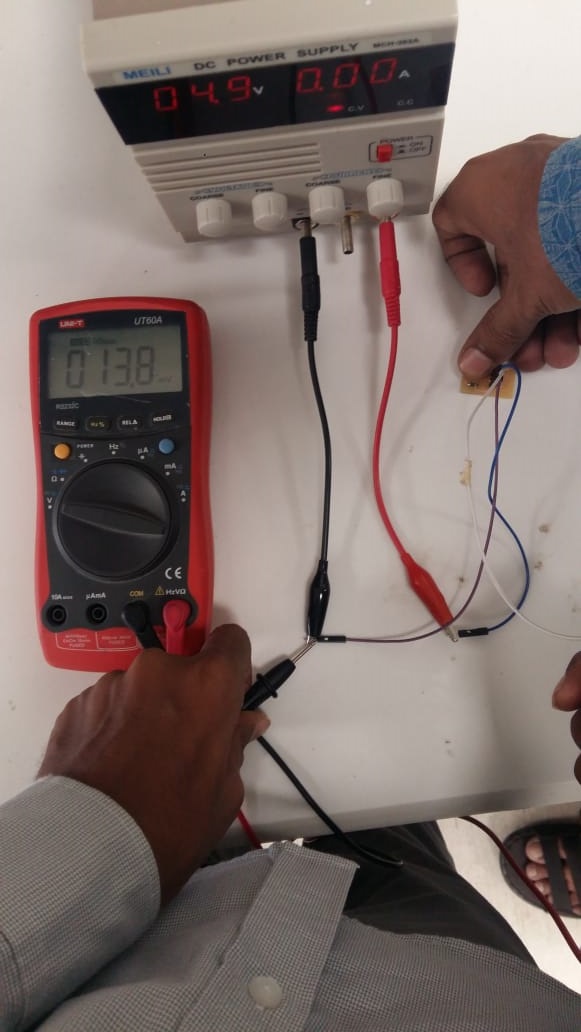
(a) Measuring Voltage levels with low intensity of light
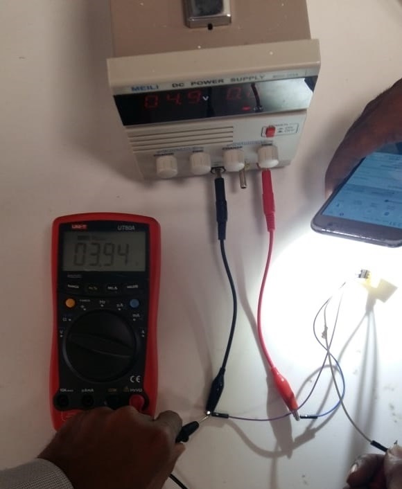
(b) Measuring Voltage levels with high intensity of light
HC SR-04 Ultrasonic sensor is used by one of our group member in his individual task of this week so we used that sensor for detecting the digital signals. We have detected the change in digital signal in Oscilloscope using arduino Leonardo. A sensor is connected with arduino and the pin of Echo is connected with Oscilloscope. Arduino Leonardo is programmed to detect obstacle in front of Ultrasonic sensor, when an obstacle is present in front of Ultrasonic sensor we found change in wave in oscilloscope. The captured digital signal of ultrasonic sensor is shown below in figure. Furthermore the echo pin of sensor is connected to the pin 13 of leonardo which is also connected to led of board. The video given below shows that whenever there is change in signal led is blinking. The rate of led blink is very fast because digital signal is changing fastly.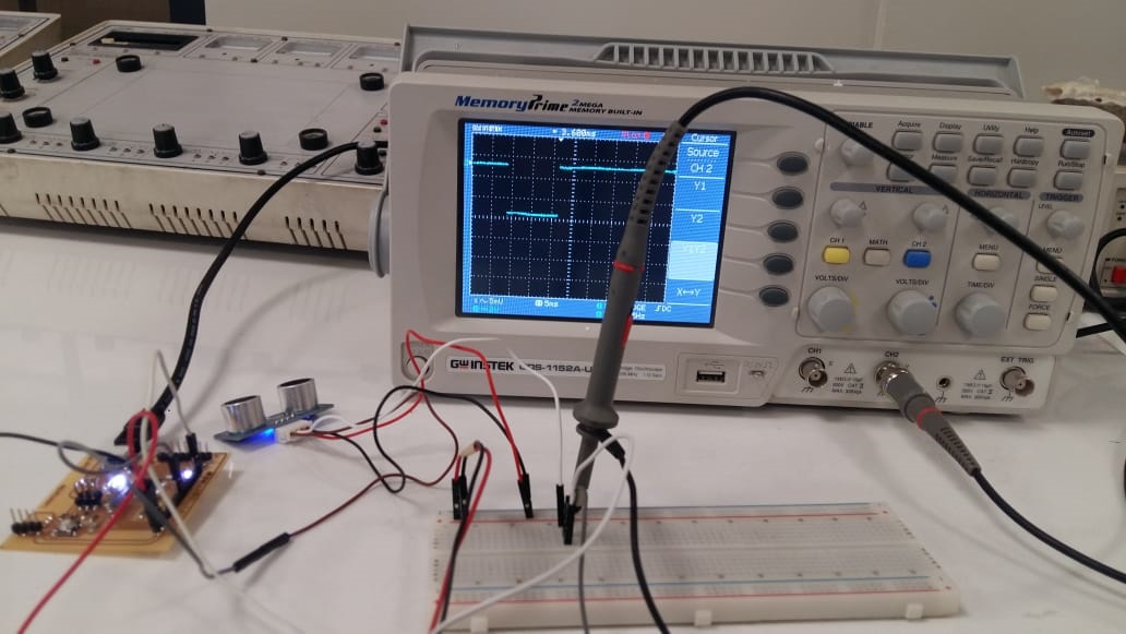
Digital signal shown in Oscilloscope
Individual Assignment: Measure something, add a sensor to a microcontroller board that you have designed and read it
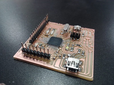
For this week we had to read some data from our enviroment, precisely that is what sensors do. Sensor converts any-form of energy into elctrical energy(digital signals/volatage levels), hence the output of sensors is fixed and it has to be electrical ennergy no matter what you give as an input. It is an input devices used to read natural parameters like temperature, pressure, light, color etc.. It is these sensors that have enabled us to make automated machines and humanoid robots. Hence for this week in fab academy we try to understand sensors and use them to our purpose with some microcontroller.I choose to use opto-electric sensors for this week assignment. Opto-electric sensor is a kind of sensor that converts light energy into elctrical energy(digital signal). I used photo-transistor mounted on a very small board and connected it to my general purpose board from embedded programming week to read light intensity. Below shoown is my general purpose board.
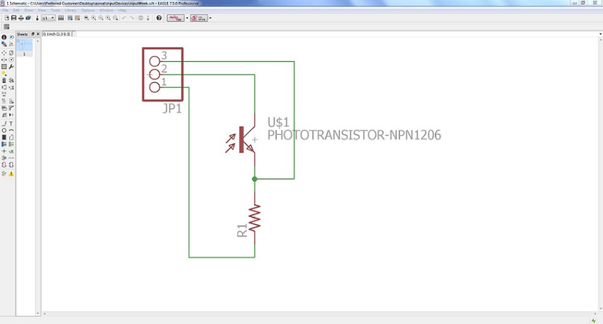
 Next i made a small PCB for my sensor(phototransistor). Phototransistor is a device that is able to alter the current flowing between emitter and collector according to the level of light it receives at base. I made this very simple PCB connecting resistor in series with phototrasistor. Sechematic shows the elctrical connection.
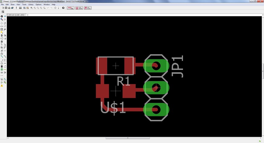
 Whereas board file shows the physical connection.
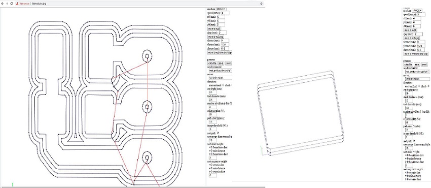
 Next i went to fabmodules.org and generted rml(machine readable) files as following. See Week4 for details.
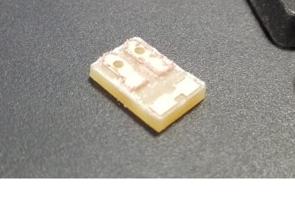
 Went to machine and did mill the board and that is it, we have our board ready.
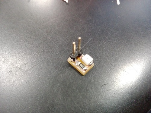
 Then soldered the board and that is it. Our board is all set for testing.
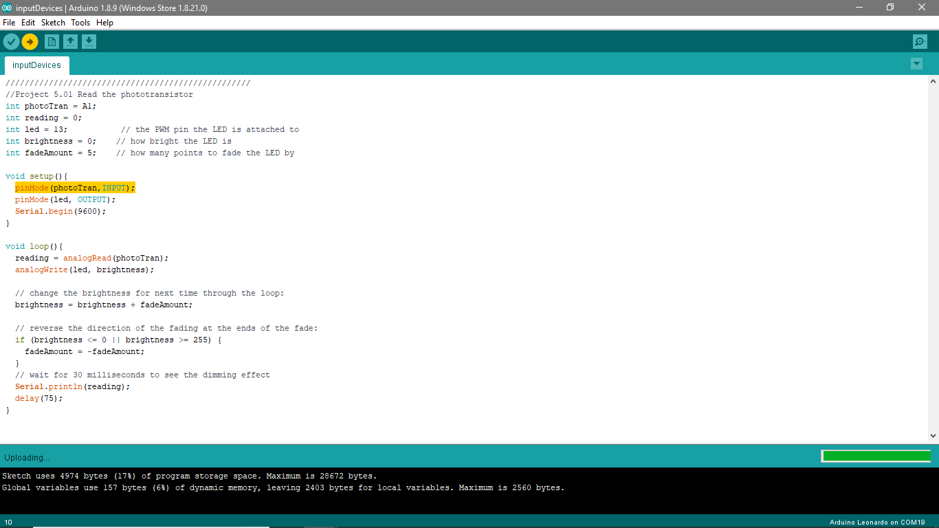
 Now let's open arduino and upload our program.
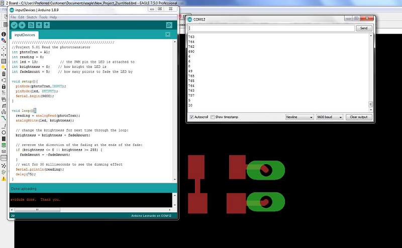
 That is it, We can see our device is working.
 Further, please follow this video to see the board working.
Click here to get design files.. Enjoy the inputs!

This work is licensed under a Creative Commons Attribution-ShareAlike 4.0 International License
Copyright © 2019 Azmat Hussain