Week no.8
- Embedded Programming
Assigments :
- Read a microcontroller data sheet
- Program your board to do something, with as many different programming languages and programming environments as possible
Programming environments
I´ve a background experience programing Atmel with Atmel Studio, also programming PIC microcontrollers using Codevision AVR C++, but it has been a while… so it’s time for an update. For this assignment I will use the Arduino IDE and WEB editor and check how much has changed in the last decade (LOL).
Microcontroller PINout
My hello board version gained some upgrades from the original design; mainly 3 switch buttons, a RGB LED and a FTDI port as I described at week 6 assignment. To achieve that, I needed to multiplex some uController PINS with the SPI connector and the RGB Led.
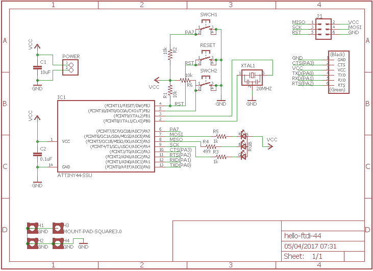
One nice feature is that I do not lose the PWM ports (same Pins) and they are available when I´m not programming the board. Other cool feature is that the led blinks when I´m programing or using the PWM pins, giving a nice visual feedback.
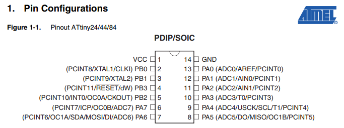
But for this configuration work properly I need to check and declare PINout correctly. So I double checked with the ATiny44 data sheet :
- Switch1 - PA7(Pin6)
- Switch2 - PB2(Pin5)
- Switch3 - PB3(Pin4) - also can work as RESET SWITCH depending on INIT
- SPI for programming - Shared Pins - and after that used by the RGB LED, also available for use thought the SPI connector
- RED-Led - PA6(Pin7) - MOSI
- BLUE-Led - PA5(Pin8) - MISO
- GREEN-Led - PA4(Pin9) - SCK
- Also a FTDI Connector for serial communication PA0 to PA3 (Pins10 to 13)
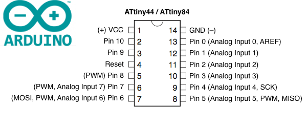
Since I´m using the Arduino IDE for programming, also need to care on how to declare those ports on the code. Strangely, Arduino IDE adopts slight different names for the PINS, numbering them sequentially and ignoring the PA0…PA7/PB0..PB3 (port A/B) names from the datasheet:
Coding & Testing
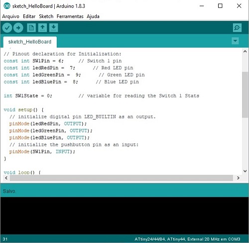
I found to be so much simple programming with Arduino IDE, clearly it is designed to be easy and straightforward. The first time user doesn’t need to worry about burning fuses or initializing the PINs it will not use. Just choose from the Tools menu your processor model, clock and programmer.
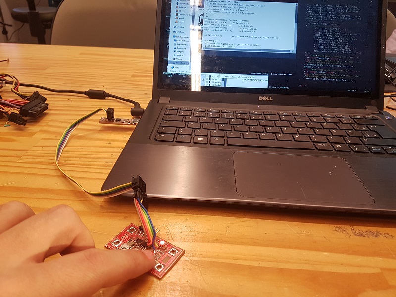
And so, I plugged my Hello Board into mine USBTiny programmer and sketched a test code. But first I looked inside the Arduino examples that came with the IDE. Also followed an excellent Tutorial recommended by Kenzo.
Before uploading the code, I needed to add the ATtiny library to the Arduino IDE to correctly select my ATtyni44 processor.
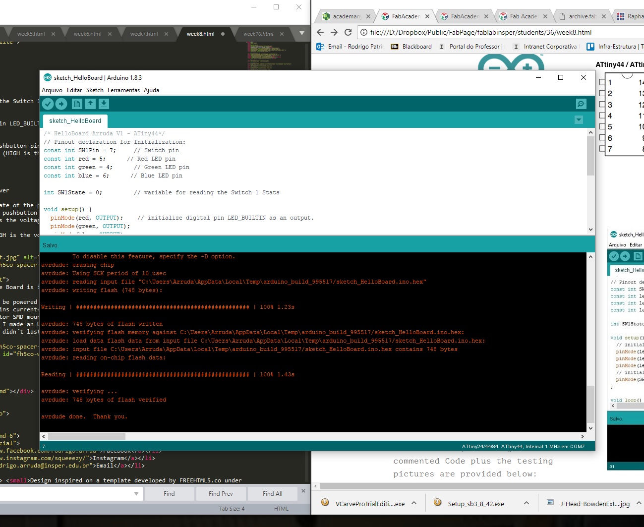
Turning on the LED by pressing the Switch Button, the original and commented Code plus the testing pictures are provided below:
/* HelloBoard Arruda V1 - ATiny44 */
// Pinout declaration for Initialization:
const int SW1Pin = 7;     // Switch pin
const int red = 5;      // Red LED pin
const int green = 4;      // Green LED pin
const int blue = 6;      // Blue LED pin

int SW1State = 0;         // variable for reading the Switch 1 Stats

void setup() {
  pinMode(red, OUTPUT);    // initialize digital pin LED_BUILTIN as an output.
  pinMode(green, OUTPUT);
  pinMode(blue, OUTPUT);
  pinMode(SW1Pin, INPUT);     // initialize the pushbutton pin as an input:
  digitalWrite(red, HIGH);    // turn the LEDs off (HIGH is the voltage level)
  digitalWrite(green, HIGH);
  digitalWrite(blue, HIGH);
}

// the loop function runs over and over again forever
void loop() {
  SW1State = digitalRead(SW1Pin);   // read the state of the pushbutton value:
  if (SW1State == LOW) {           // check if the pushbutton is pressed,if it is, the buttonState is HIGH:
    digitalWrite(red, LOW);  // turn LED on (LOW is the voltage level)
  } else {
    digitalWrite(red, HIGH);   // turn LED off (HIGH is the voltage level)
  }
}
Problems found:
- Programming the Board is inconsistent !
- Board needs to be powered from FTDI for successifully programming - the shared pots with the LED´s drains current
- The SPI connector SMD mounted is not the ideal, and with continuous use it broke the board contact (and I made an Ugly Fix by jumpering the SPI direct to the uControler PINs... Witch also didn´t last long.
Truly there was a problem with my red Hello Board, a connection wire underneath the SPI connector has broken with constant plug in and out of the SPI cable. So I took of the connector out and soldered jumper wires directly at the processors PINS.
But after the fix, the board was dead… couldn’t program anymore, keep receiving different message errors. The device was not recognized by the IDE.
After browsing the errors through forums and tutorials on the internet, I found some reports of users with the same errors. It all pointed out to an incorrect burn fuse caused by a bad programming, fluctuating contacts or an external clock misconfiguration.
Debugging Log:
- Followed this tutorial on how to burn fuses and this fuse calculator.
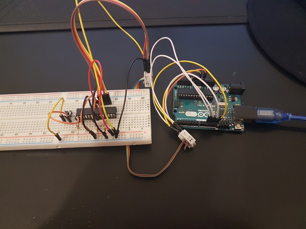
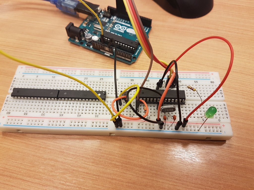
- Mounted an Arduino Breadboard with a 328p for testing
- Tested different programmers (other USBISP, serial FTDI FT232, ArduinoISP) with the breadboard and my dead HelloBoard
- Extracted the oscillator from the dead board and replaced by a 20MHz external crystal with 10pF capacitors
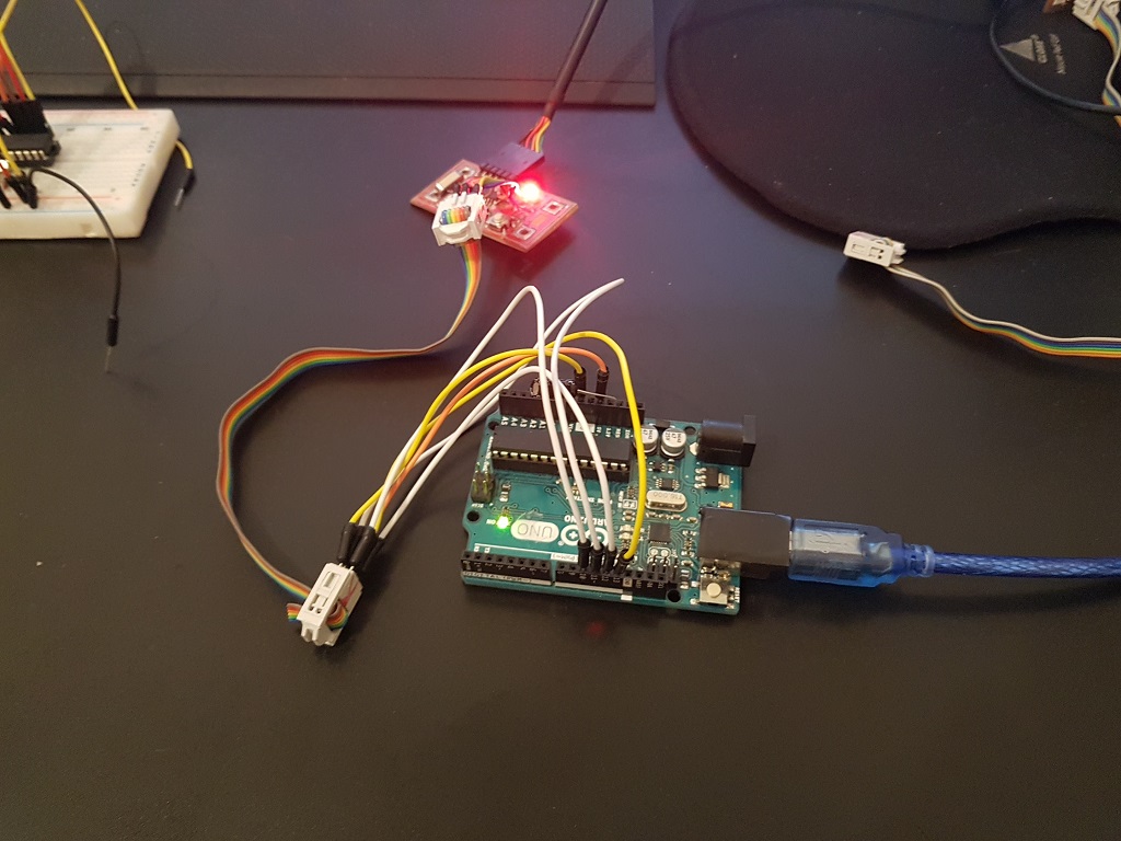
- Programmed the dead board with the external crystal fix with a Arduino ISP, following this tutorial.
- Success !! Brought back the HelloBoard from the dead !!
Also worth checking the assignment at week 10 - to check if my board was really working I tested the output again with an Blinking RGB led code