Week no.10
- Output Devices
Assigments :
- Add an output device to a microcontroller board you've designed and program it to do something
Hello Board Output Test
At first, I made a simple test app for the RGB output of my Hello Board. As I showed at week 6, the LED is connected in a pull up configuration to the ports PA4,PA5,PA6 pins. I used Arduino IDE 1.8.5 and started with the sample "Blink" program re-configured for my Hello Board PINs connected to my RGB and expandend the code to cycle trough the three LED colors.
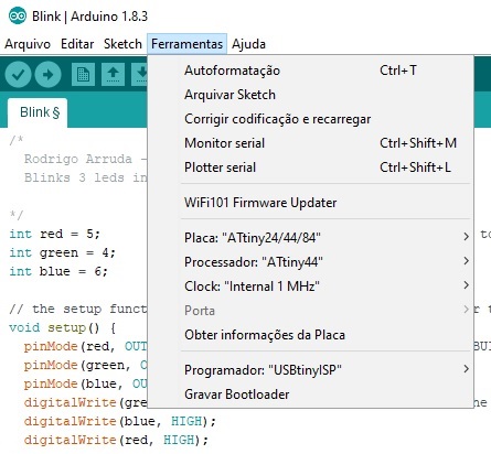
To upload the code I used my FABISP connected through the ISP port of the Hello Board. The configurations for the Arduino IDE where:
- Board : Atiny24/44/84
- Processor: Atiny44
- Clock : Internal 1 MHz
- Programmer: USBtinyISP
The code is simple and it fades in and out changing colors, endless. The source code is shown bellow:
/*
  Rodrigo Arruda - Fabacademy 2017 - Insper Brazil
  Blinks 3 leds in serie, with 1sec. delay, repeatedly.

*/
int red = 5;                  // the pin the LED is attached to
int green = 4;
int blue = 6;

// the setup function runs once when you press reset or power the board
void setup() {
  pinMode(red, OUTPUT);       // initialize digital pin LED_BUILTIN as an output.
  pinMode(green, OUTPUT);
  pinMode(blue, OUTPUT);
  digitalWrite(green, HIGH);  // turn the LED off (HIGH is the voltage level)
  digitalWrite(blue, HIGH);
  digitalWrite(red, HIGH);
}

// the loop function runs over and over again forever
void loop() {
  digitalWrite(red, LOW);     // turn the RED LED on (LOW is the voltage level)
  delay(1000);                // wait for a second
  digitalWrite(red, HIGH);    // turn the RED LED off (HIGH is the voltage level)
  delay(1000);
  digitalWrite(green, LOW);
  delay(1000);
  digitalWrite(green, HIGH);
  delay(1000);
  digitalWrite(blue, LOW);
  delay(1000);
  digitalWrite(blue, HIGH);
  delay(1000);
}
The first attempt was a failure, I got this error message: “avrdude: initialization failed, rc=-1 Double check connections and try again, or use -F to override this check”. I upgraded the Windows driver from Adafruit tinyISP (libusb v1.12), but still nothing.
After debugging and testing with a multimeter, I find out the FABISP couldn’t supply enough current for the Hello Board. The workaround I found was to connect the USB-Serial converter from another USB port trough the extra FDTI connector to provide the extra power. It worked, and the result was:
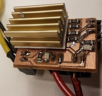
Heat Bed Control
Moving forward in the output device, I choose to make a Power Board to control the Heated Bed of my delta Printer (final project). This new board should interface with my Hello board allowing to power up an 80W heating element with a 5v/20mA signal directly from the ATtiny44 PWM pin.
Part List:
- Comercial HeatBed Model MK2 - Dual Power (12V or 24V)
- Dual Mosfet RFD16N5 SMD from the FabAcademy Iventory
- Used Computer PowerSource 500W
Schematics
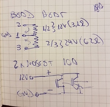
I was worried with the power dissipation on small packages Mosfets, so I I took advantage of the dual imput power of the bed to wire in a different way and use 2 Mosfets insted of one. Each one would drive half power using the tree wire conection provided as a show in the sketch:
Another advantage of this approach is that I can use the PWM pins to modulate the power drain for the heater. I can also switch the two output for maximum power or just modulate one to maintain the temperature once it reaches the set point with minimal current drain.
In future implementations I can also measure the system response, get the transfer function and use modern control techniques to get better (and quick) performance from the printer HeatBed.
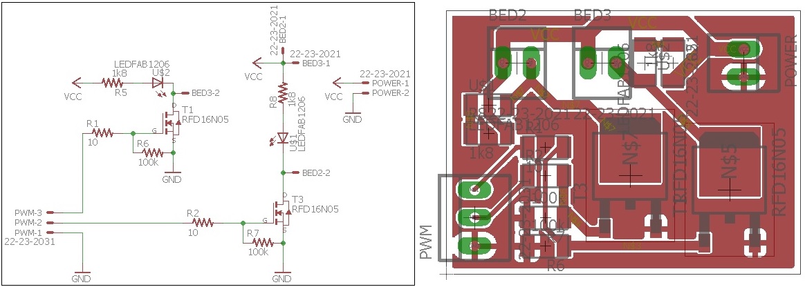
From Sketch to Eagle Schematics and board:
Here are the original project files.
Conclusions
The output Board worked as expected, with both mosfets you can Switch independently the two sides of the bed coil. It was successfully driven by the ATtiny44 pin signal.
Since I didn’t implement the temperature sensor (Yet!), I could not set the target temperature. So I just used the same code from the RGB LED just changing to PIN7 and PIN8 and pulled the signal available from the SPI connector to validate the signal output drive.
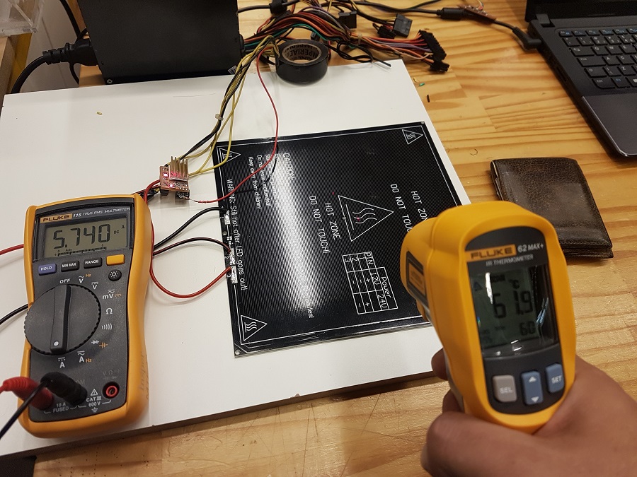
Each mosfet drives 3,2Amps, this current can be easily handle by the driver that runs cool (30ºC) with a passive heat sink. As the temperature rises, so rises the internal impedance of the mosfets. I notice a small drop on the current for temperatures above 70ºC.
The Bed Heated from 18ºC to 110ºC in 9 minutes, a decent performance. Maybe the most significant aspect of this project is that it isolates one major source of problems in 3D Printer board - the Bed Heat element.