"Yeah, and a large part of what I think about is what music performance looks like and how it functions, what sort of communication is really happening when you see musicians on the stage and if that communication isn’t there then it’s less live in some senses." - Miller Puckette on Max and Pure Data
Final Project
Context
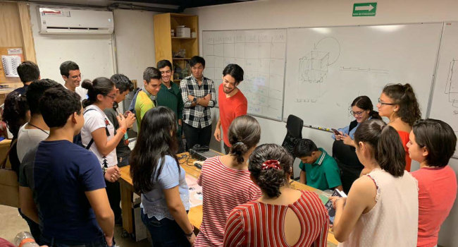
Since I was a kid I was attracted to art, science and technology, I just didn't know it was possible to mix these. When I was struggling to choose a career between filmmaking, economics, psychology, and mechatronics engineering, I chose the later, as I was a little more of an introverted inventor. As I discovered the concept of makerspace and that there was a Fab Lab in my city, I went there without a doubt, not knowing what will happen, but sure that there I would find something amazing. I begin working there a few months later and, although it's been very intensive, I feel is kind of like a dream job for me. I discovered that the mix of art+science+tech was possible last year with my first (ever) personal project and prototype: P_A+L! Since then, I have been involved in a number of projects and workshops always seeking the intersection of this three areas.
First Project Proposal - Art Academy
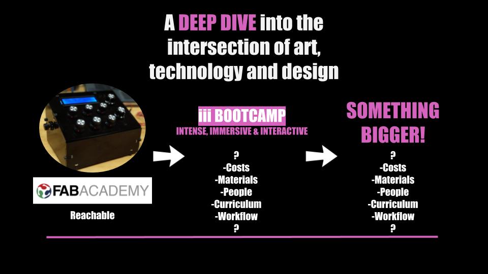
At first I wanted to make my final project about an Academy on digital arts, with the structure of the Academany Fab Academy, Bio Academy, Fabricademy, scheduling each week for a different tool like VR/AR/MR, videomapping, kinetic sculptures and others.
I asked Neil about this during the first lecture, and he told me to make a proposal, keeping in mind that making an Academany is not only the schedule and the subjects, but the infraestructure, the people, how to grade assignments.
Second Project Proposal - Modular console
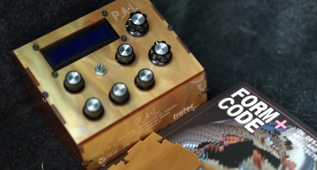
So I figured it would be pretty big for a Fab Academy project, so what I will do is make an improvement on a project I have called P_A+L! (Processing _ Arduino + Lots of sensors!). It is a console for controlling visuals on live performances. Right now it only has a few potentiometers, has an Arduino inside and a protoboard. Through the FabAcademy I will design and manufacture a working PCB, and design and prototype a few controls aside of the potentiometers.
Inspirations && Aspirations
Author & Punisher - Tristan Shone makes his own instruments to play extreme music. What I like about this project and find inspiring for mine is that sense of realness that has on his machines. The instruments are made of metal, and are really heavy, and that changes the whole experience of
Explaining DIY Controllers - In this video, Tristan shows how the instruments work, using digital interfaces.
Ideas && sketches
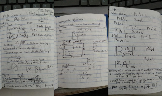
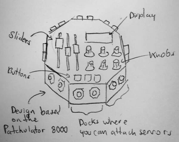
I made a few sketches of how the console would look like:
I want the project to be sorrounded by this two ideas and concepts, both in aesthetics and in functionality:
Kintsugi, the Japanese art of repairing broken pottery with gold. I like the aesthetics and the philosophy behind this.
Analog synthesizers, that uses analog circuits and analog signals to generate sound electronically.
I made this moodboard to illustrate better this ideas:
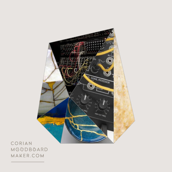
I think these two concepts have some ideas that can help me through my journey developing the final project. Here I make a list of a few concepts/ideas that come to my mind while thinking about Kintsugi and Analog synthesizers. These have no particular order, it's just a brainstorm of ideas:
Modularity
Patches
Resilience
Philosophy of living
Repairing
Connecting
Devices with a meaning
Organic
Progress
So I figured it would be pretty big for a Fab Academy project, so what I will do is make an improvement on a project I have called P_A+L! (Processing _ Arduino + Lots of sensors!). It is a console for controlling visuals on live performances. Right now it only has a few potentiometers, has an Arduino inside and a protoboard. Through the FabAcademy I will design and manufacture a working PCB, and design and prototype a few controls aside of the potentiometers.
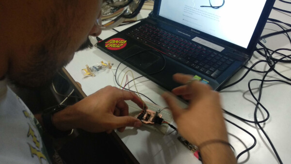
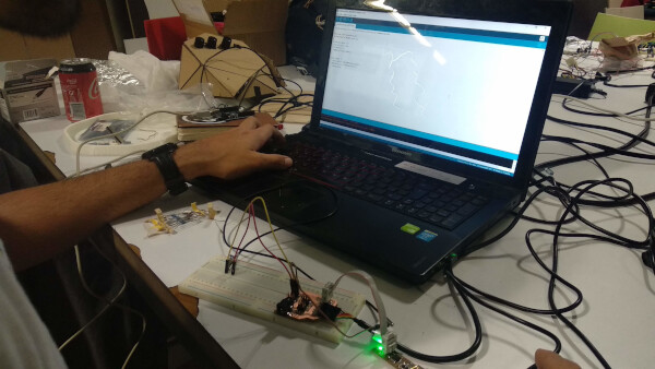
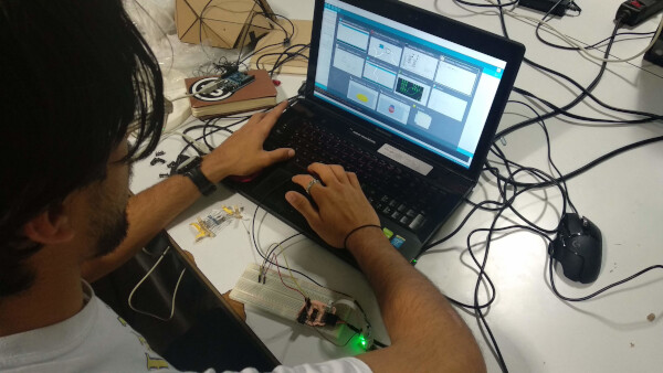
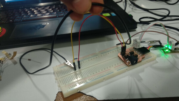
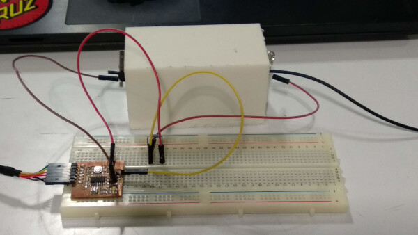
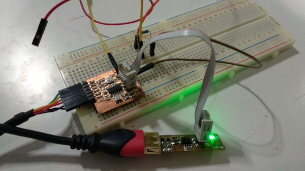
In my Input Devices week I designed a board to connect a sensor, in this case, a potentiometer, to Processing, through serial port. The end result is very similar to the one in my P_A+L! video, but this time I'm not using an Arduino, but my own board.
Multiplexing
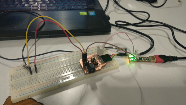
To connect multiple outputs or inputs to the microcontroller, without using many pins, I decided on using a Multiplexer CD4051 (Datasheet). I followed this tutorial to make the circuit of the multiplexer connected to the microcontroller.
In KiCAD I found a 16-pin IC called 12-BIT_ADC_8CH_SOIC, under the fab library. I'll try to use the footprint of this component simulating the CD4051 multiplexer. To see if the size of the footprint is the same as the CD4051, I used the Measure tool under the Inspect menu on the PCB design window. The width is 3.56mm and the height is 9.91mm. I used this reference to compare the sizes of the components. The width is a little bit smaller on the footprint, but it shouldn't be a problem as I should be able to solder the component on the traces.
Electronics Design and Production
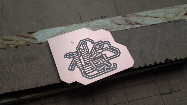
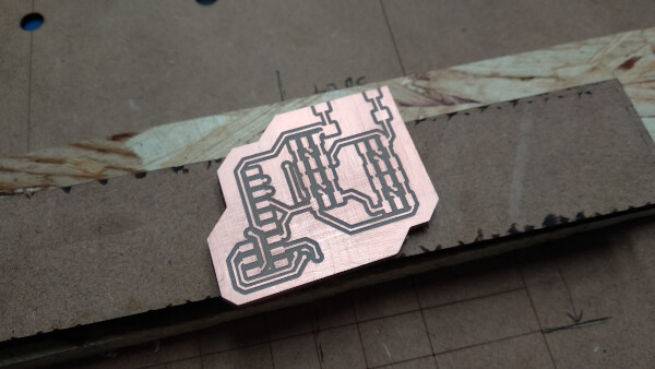
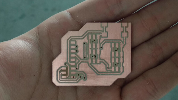
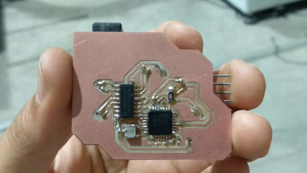
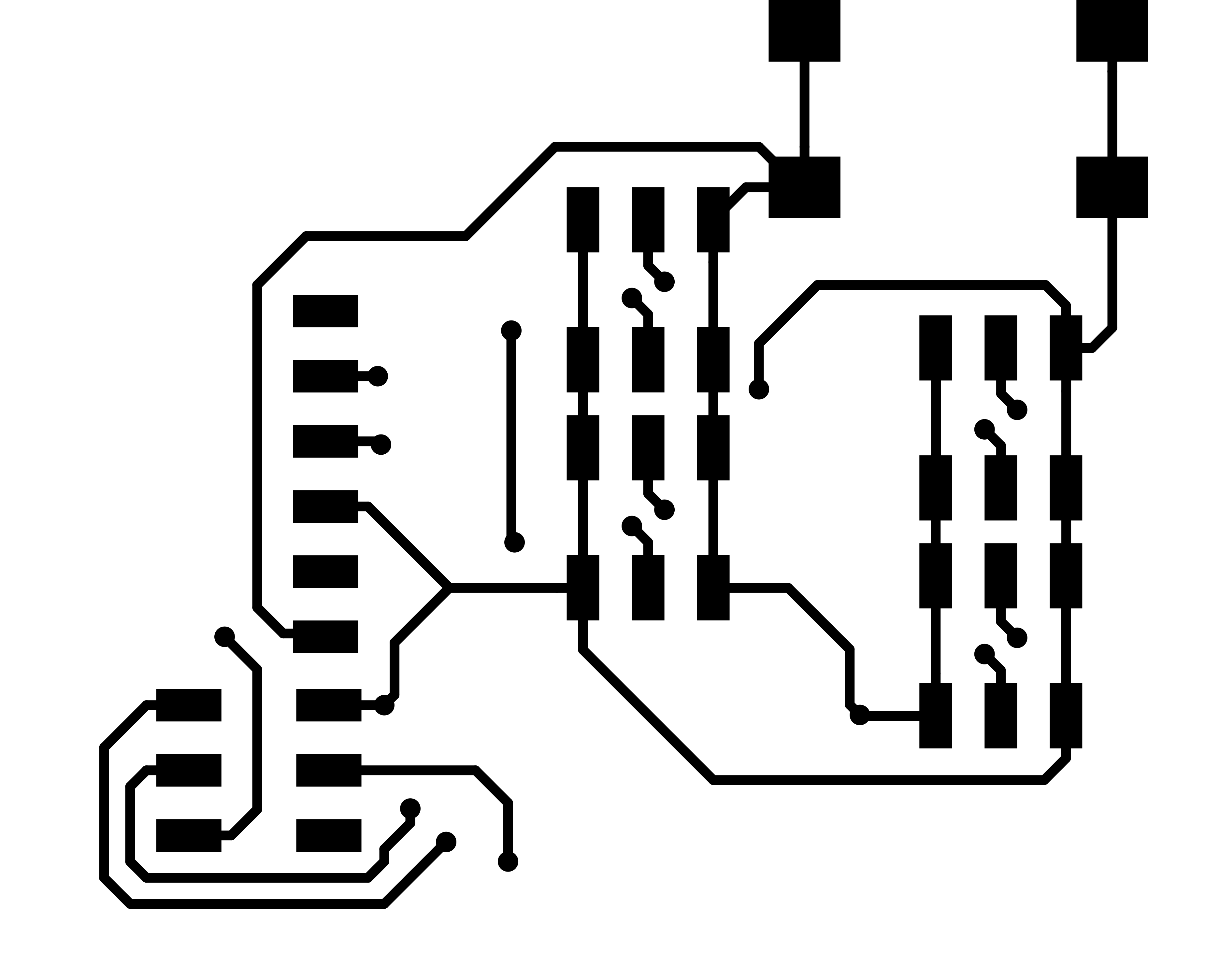
I begun designing in KiCAD the electronics for the main board of the console, using one multiplexer. To reduce the size of the board and to experiment on grouping components as the header pins where the sensors will attach, I decided on doing a double-side board. I learned how to design double-side circuits on KiCAD, and fabricated this board. On this board I used an ATMEGA328P as the microcontroller.
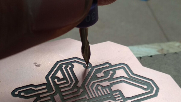
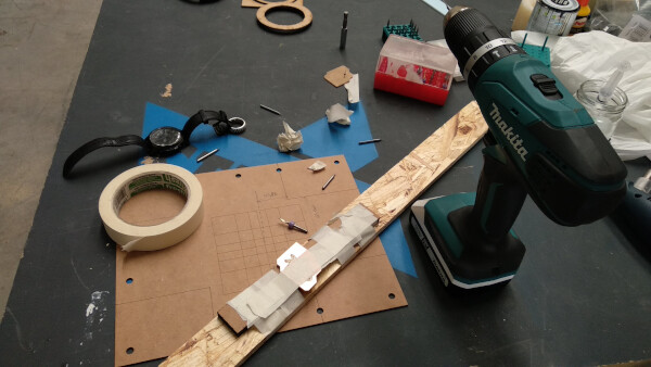
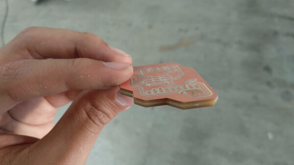
To connect both sides of the board between each other, I had to make drill holes on the points I decided on the design. To do this I first used a V shape drill bit to make a little hole, and then used a 1/32 drill bit to make the hole.
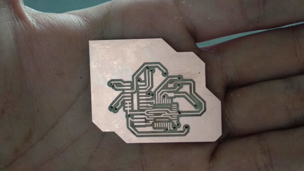
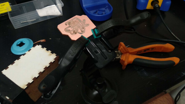
I then solder pins on the holes to connect the paths on both sides of the board, and cut the remaining parts of the pins. I then soldered all the components on both faces.
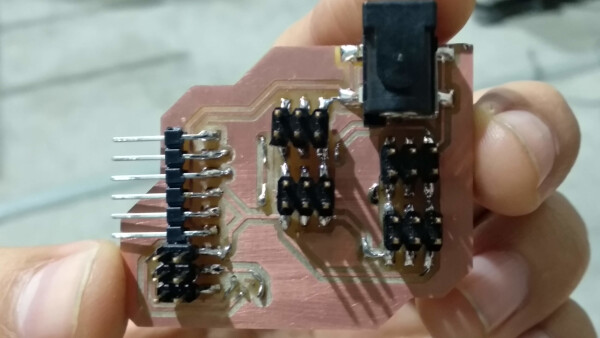
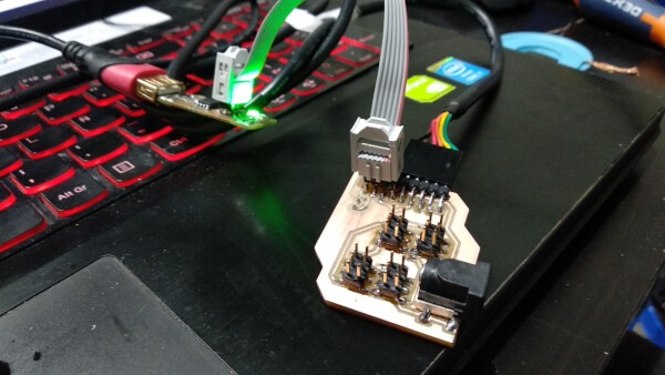
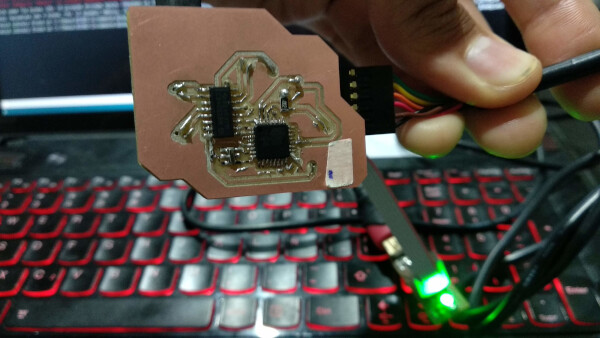
I then burned the bootloader using my fabISP. I connected a button as a test sensor to see if it worked and it did. I test this button on every header pin of the multiplexer, and they all worked.
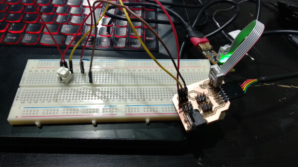
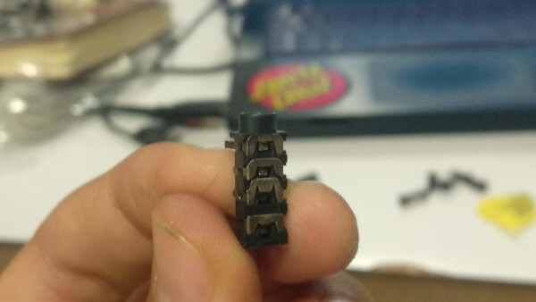
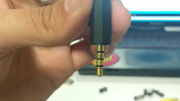
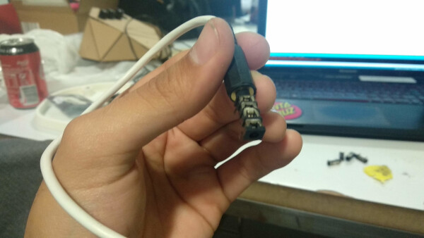
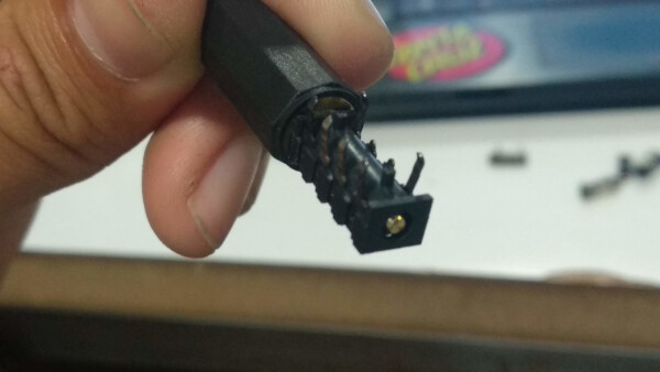
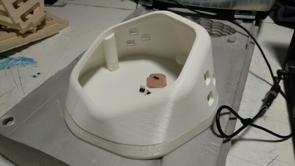
To connect the external sensors to the console, I used a 3.5mm plug. I connected the patch cable to my board through the 3.5mm female plug and the other side of the patch cable to a rubber cord I'll use on my soft sensor (down in the section of Soft Sensors I explained what is the electronics on this sensor). I tested, and as the button, it also worked.
Shape
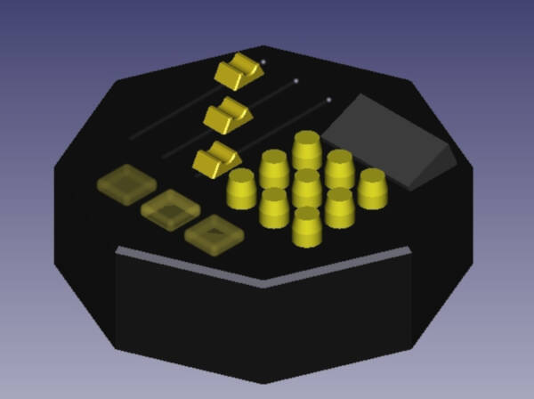
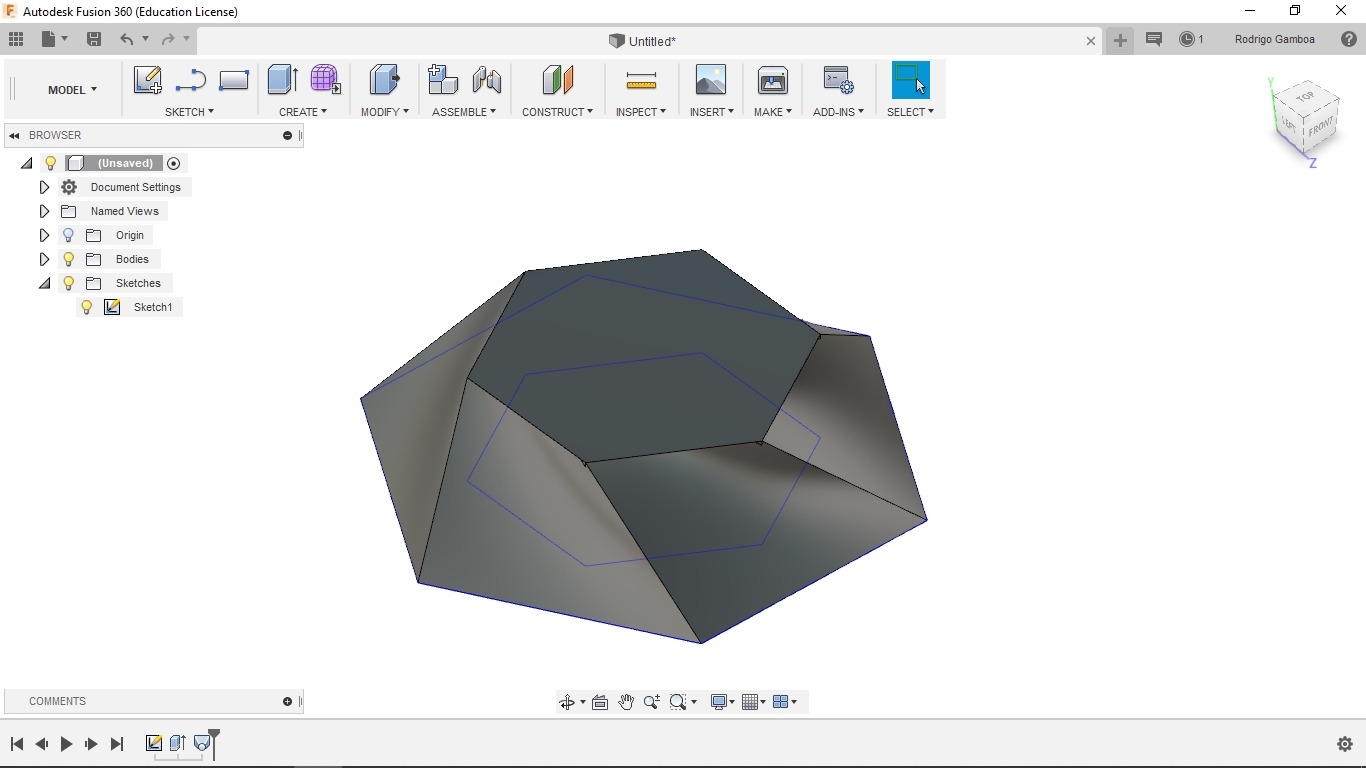
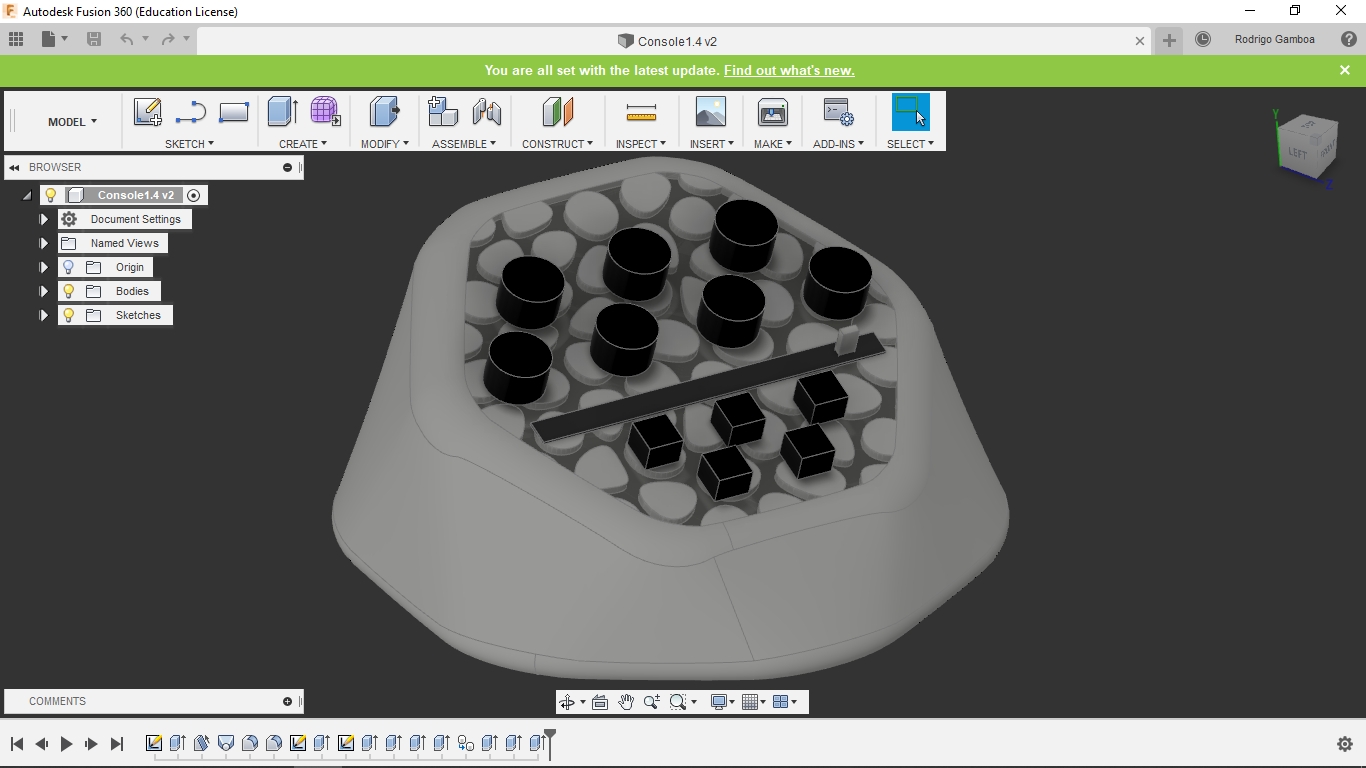
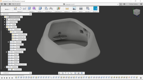
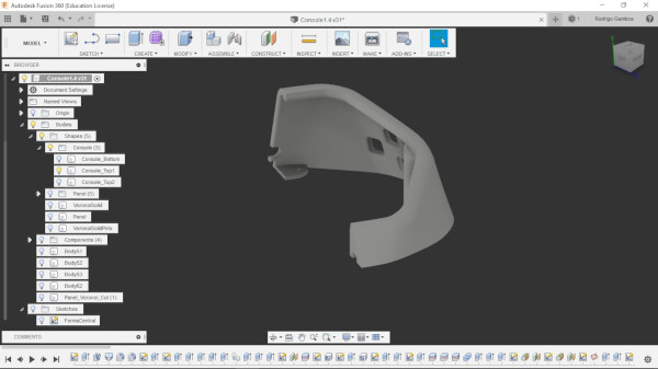
I used Fusion 360 to design the shape of the console. I begun with two hexagons with different rotation, and I applied loft on the faces to create the 3D shape. At first it was a little bit too sharp, so I added an inclination on the top face and applied fillets on all of the corners, until I reached this shape. I added some components to see the proportions of the knobs and slides.
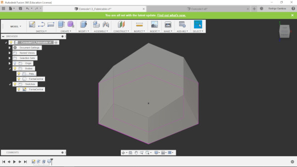
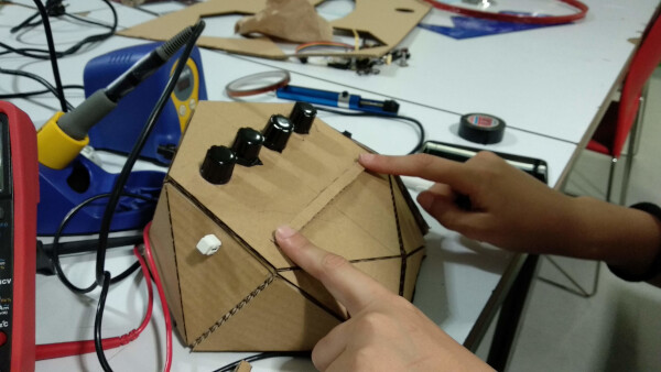
I wanted to fabricate the console to make some user testing forproportions, ergonomics, etc. So I reduced the model to make it low poly, and fabricated it using Pepakura. I lasercutted the shape on cardboard and assemblied it.
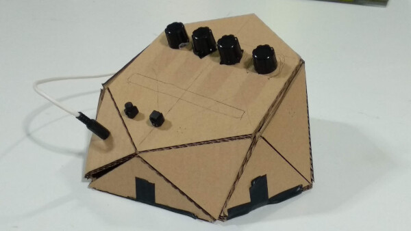
I made some user testing with my tutor that have experience with this tools. She helped me with th organization and spacing of the components on the panel of the console.
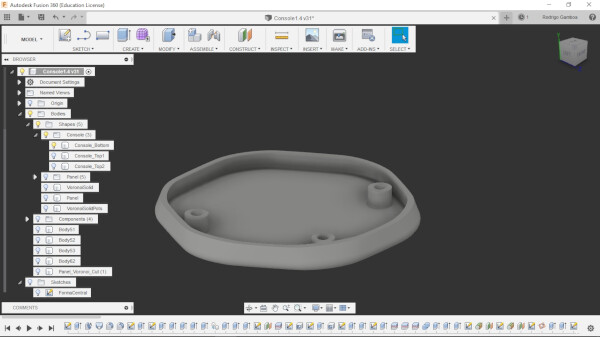
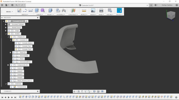
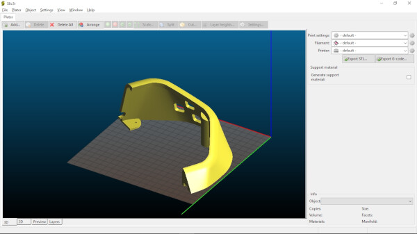
After doing this test, I separated in the model the panel, that is the flat surface where the components are mounted, and the organic shape. I wanted to 3D print this shape on the Prusa printer we had at the lab, so to make it fit in the printing area, I had to divide the shape in three parts: bottom, top left, and top right. I used slic3r to generate the files and the staff from the Fab Lab IED Madrid sent it to the machine to print. This part is documented in my 3D scanning and printing assignment.
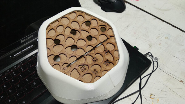
After printing the three parts, I glued the two top parts, and added with glue some magnets on the columns at the top and at the bottom parts. The idea is to accces the interior of the console by just applying some force and use the magnets to snap-close the console. This idea of the magnets worked pretty well.
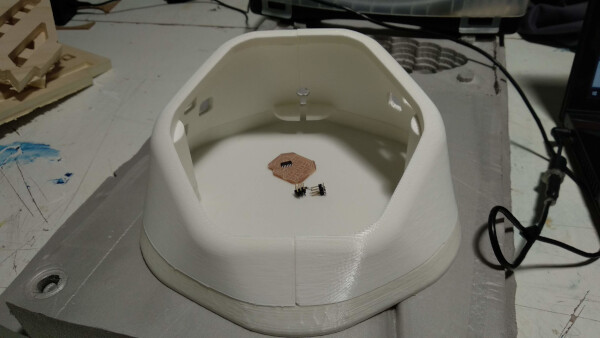
I was very happy with the final printing quality and shape.
Soft sensors
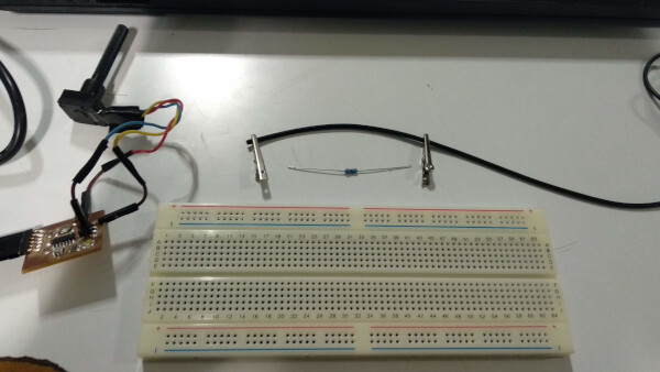
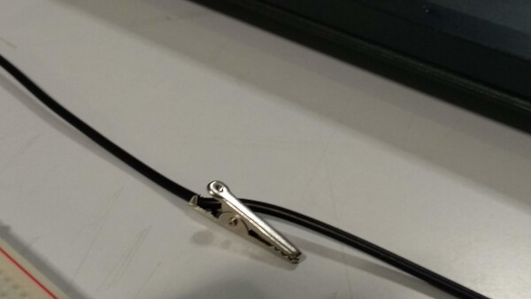
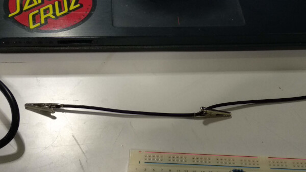
I wanted to fabricate some soft sensors to twist, bend and play while using the console and making visuals. To make this I used a conductive rubber cord stretch sensor. I used this tutorial to make the connections.
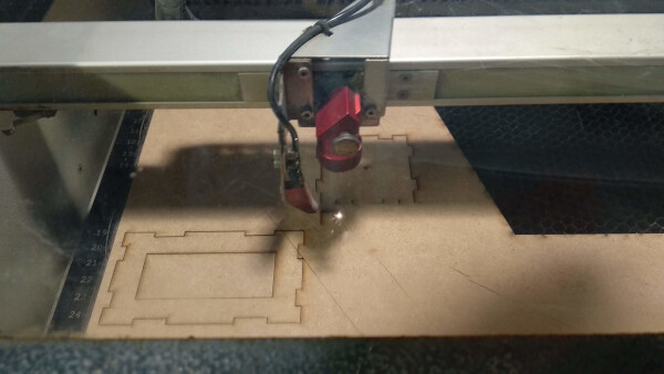
I wanted to make a test using silicone with the rubber sensor inside, so I fabricated a box to contain the silicone mix and hold the sensor inside.
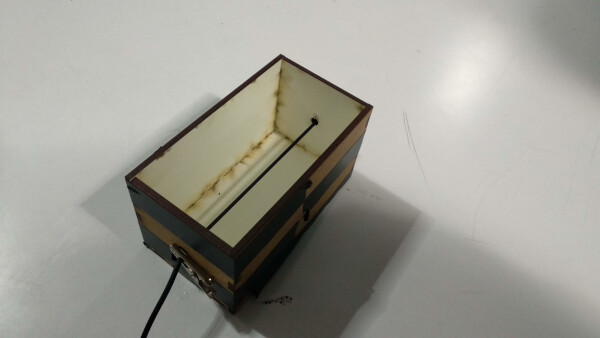
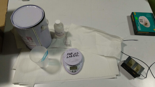
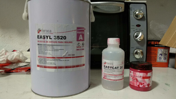
I used the same silicone as in my molding and casting assignment.
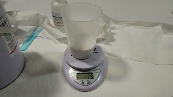
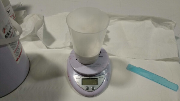
I poured the silicone mix inside the box with the rubber and let dry for 4-5 hours.
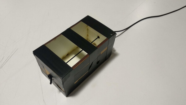
After that time, the silicone was dry. I actually really liked the texture and the density of the block, although the sharp corners where a little bit uncomfortable to twist, but the strenght and effort you have to make to twist and bend this block it's really aligned to what I want this to become.
I connected the outside parts of the rubber cord to my BoredBoard, from my input device week. I used the same interface application in Processing from that week to visualize the response of the sensor.
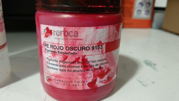
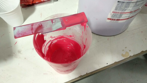
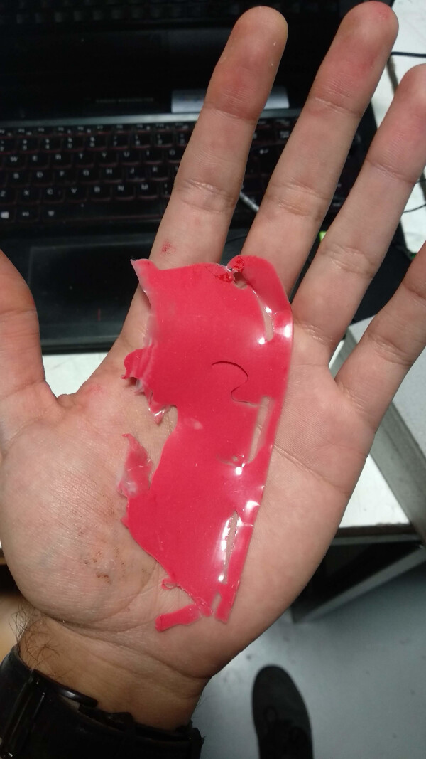
I wanted the silicone to have some color, so I did a test with a paste red pigment. This pigment is for coloring resin, so I wasn't sure it would work on the silicone. I made a little mix and poured a little bit of the paste, mix it until it was all colored and let it dry. The silicone colored succesfully, and it seemed that it didn't lose it's properties.
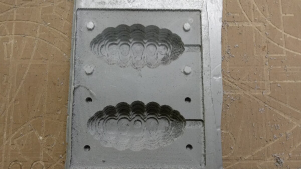
To make the final silicone sensor, I desgined and milled a low-resolution shape, because I think it would be nice for the feeling and grabbing. I milled it with the CNC machine on foam.
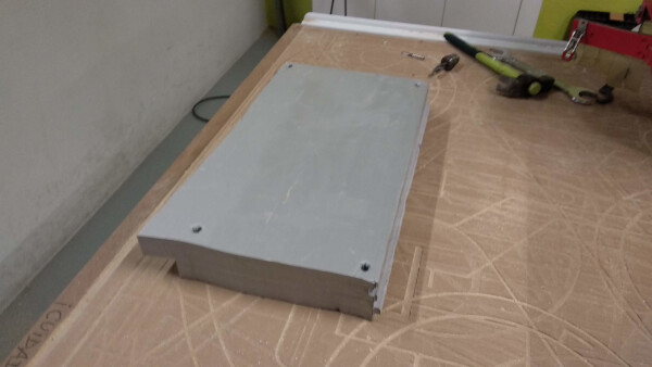
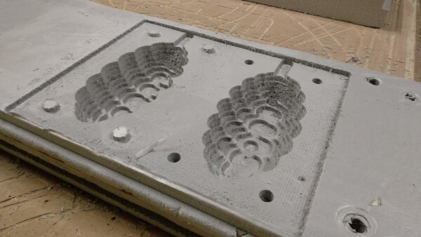
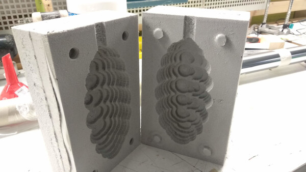
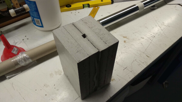
The foam block has hole for pouring the silicone mix, and to hold the connector of the sensor.
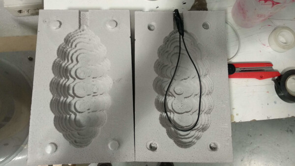
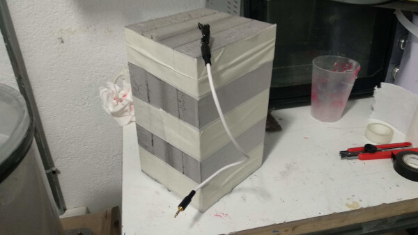
I closed the foam blocks using tape. The little grippers I made on the design were very helpful to close tight the blocks. I then made the mixture and poured it. The process was a big mess, so I had to make a bigger hole to poured the mix. I let the mixture dry for 5-6 hours.
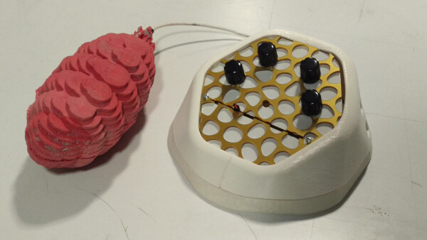
Opening the blocks was a challenge as I forgot to put mold release on the foam. This was the final result of the sensor. I was very happy with the shape, the density and weight, as is a little heavy and you really have to make some force to bend it and twist it.
Panel
For the panel for where the potentiometers and sliders are attached, a lasercutted two layers for test on MDF 3mm, one as the base, an another one with a voronoi configuration as aesthetic purpose.
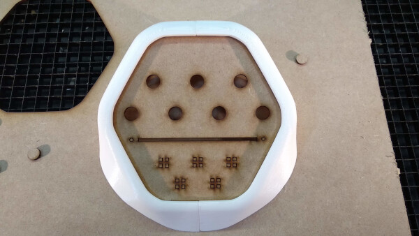
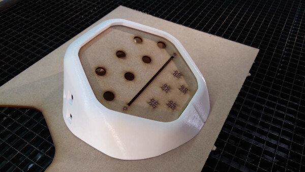
I was very happy of how it looked, so I made another two layers lasercutted one white 3mm acrylic for the base, and gold 3mm acrylic for the voronoi configuration.
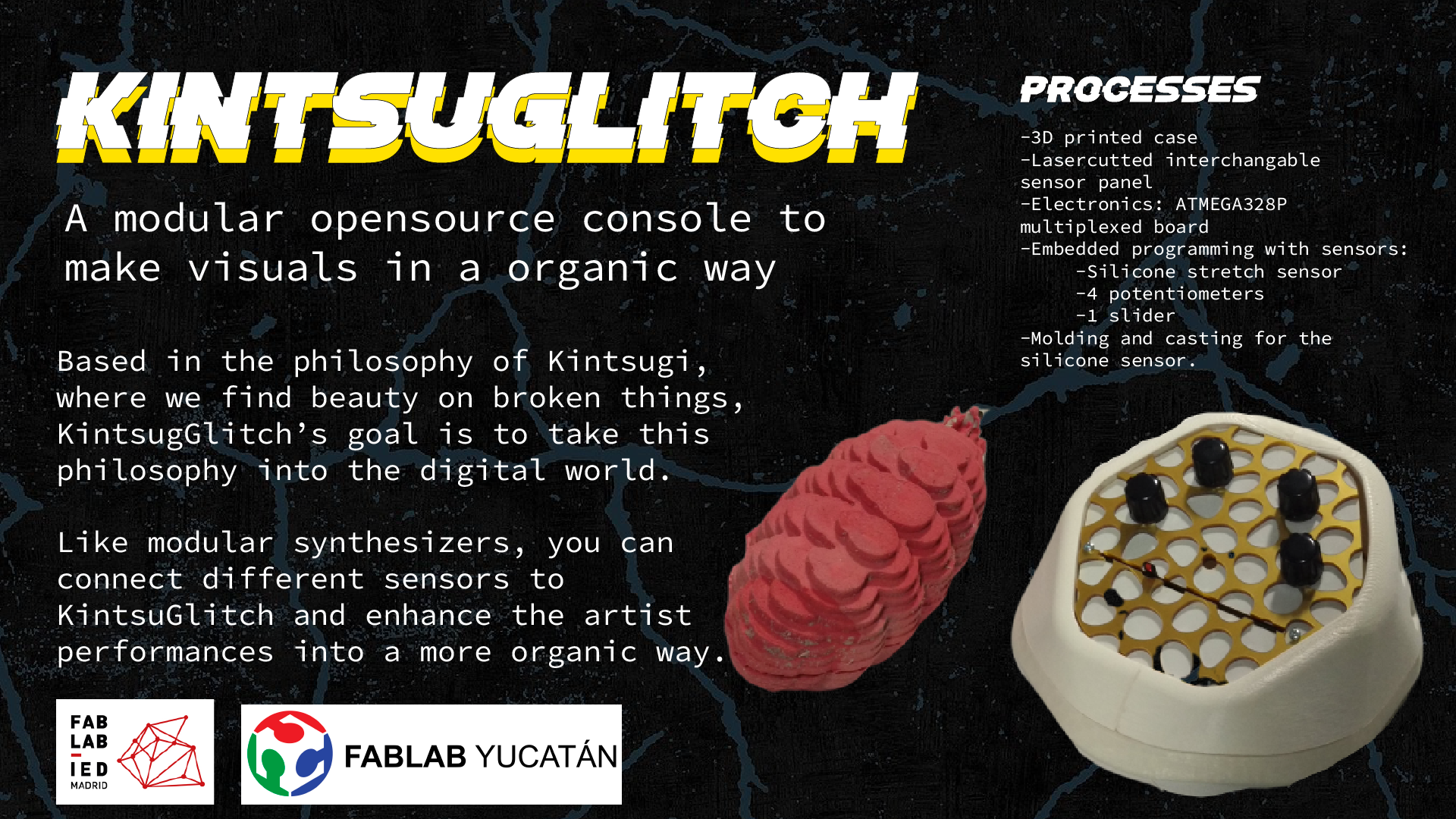
This is the final presentation of the project, with the console with 4 potentiometers, 1 slider, and connected to the soft sensor through a patch cable.
License
The license I choose for my project is the Creative Commons Attribution-NonCommercial-ShareAlike 4.0 International. I talk more in depth about this in the intellectual property week assignment, but basically I want to create a community that helps on building on the project, but at the same time, I want to explore the possibility of upgrading this project into a commercial product. Probably in the future I'd choose a Free Culture License for the project.
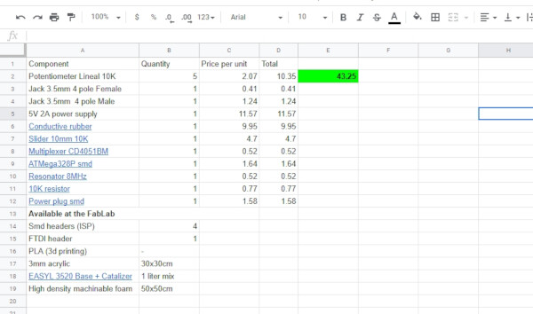
BOM
Final Presentation and Video
Files
- Console (Complete) .f3d (Fusion360)
- Console Bottom .stl
- Console Top (Complete) .stl
- Console Top 1 .stl
- Console Top 2 .stl
- Control Panel Base .dxf
- Control Panel Voronoi .dxf
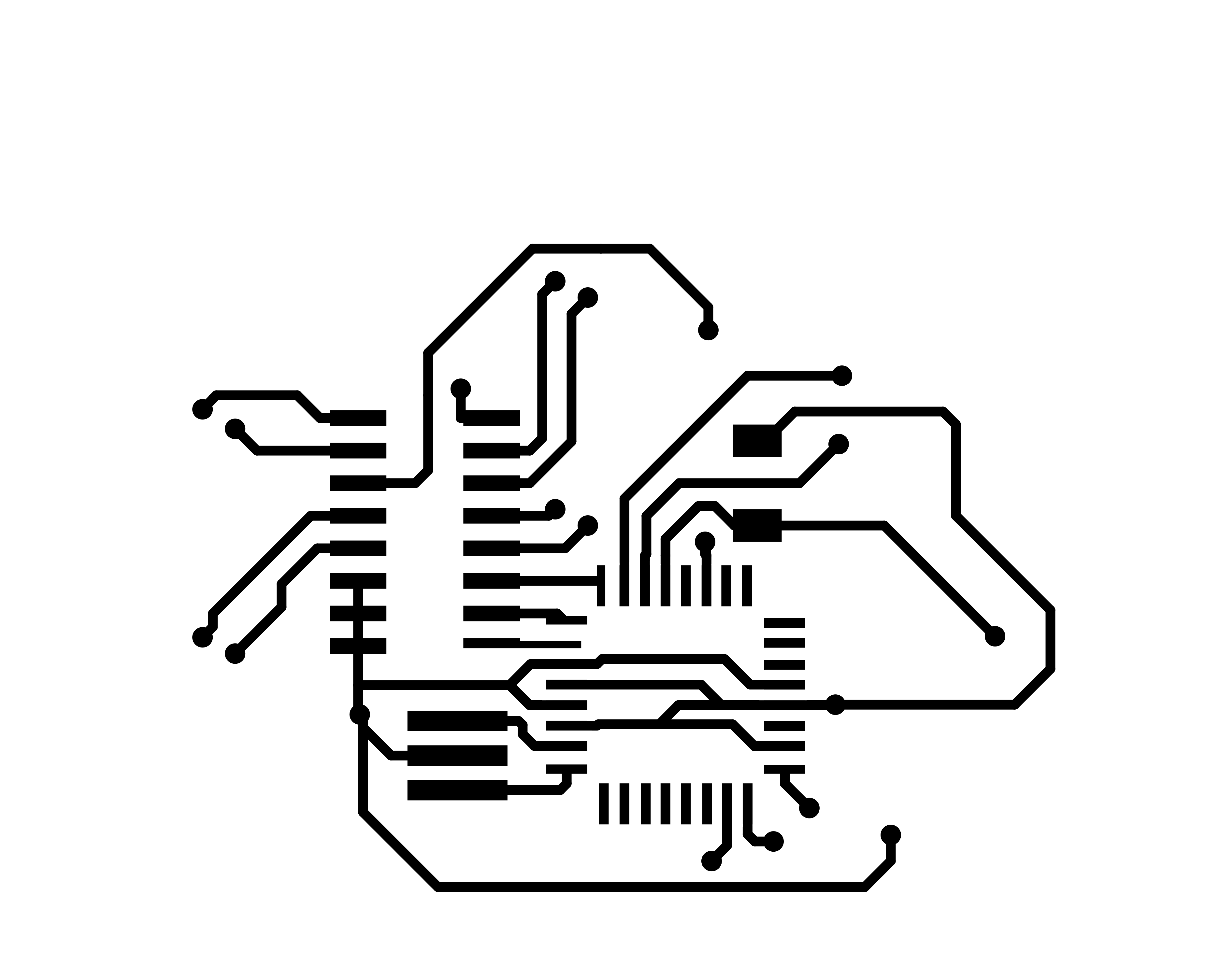
- Traces Board (Front Side) .png
- Profile Board (Front Side) .png
- Traces Board (Back Side) .png
- Profile Board (Back Side) .png
- Data Serial Test Code .ino (Arduino)
- Multiplexer Test Code .ino (Arduino)
- Soft Sensor Test Code .pde (Processing)
- Electronics Design Project (Complete KiCAD folder)
- BOM .pdf