INDIVIDUAL ASSIGNMENT network
OBJETIVES: The objective of this assignment is to communicate two boards through a network protocol.
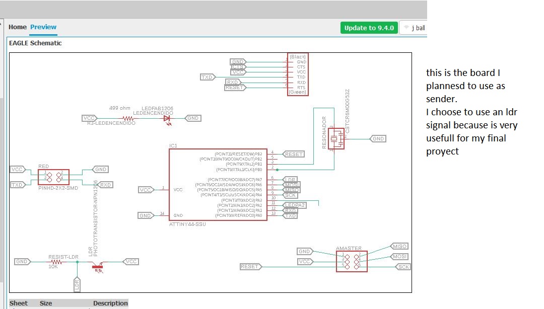
In my case, a board with an LCD sensor must send a signal to a board that will be responsible for moving a servo depending on the light detected
input ldr network
because the board made in the assignement input does not have the proper connections it is not prepared to communicate with another, so I design and manufacture another
The board with the light sensor will work as a master and send a signal to the servo control board (slave) so that it moves under the conditions indicated by the software
STEP 1 : FABRICATION PROCESS OF MASTER
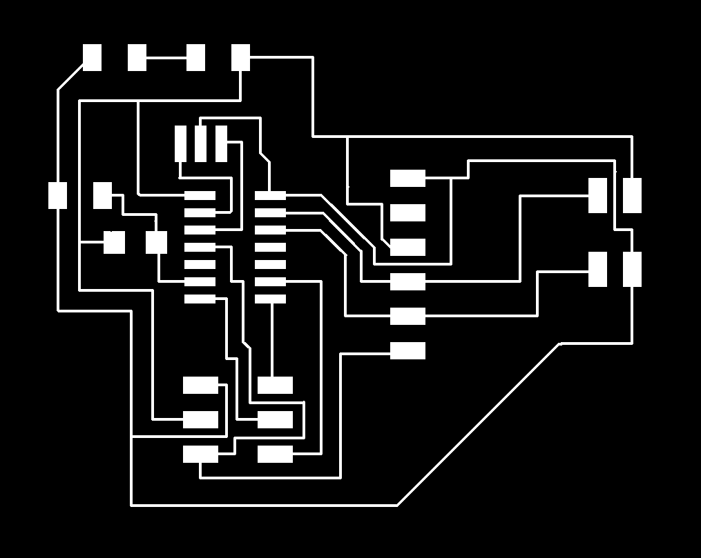
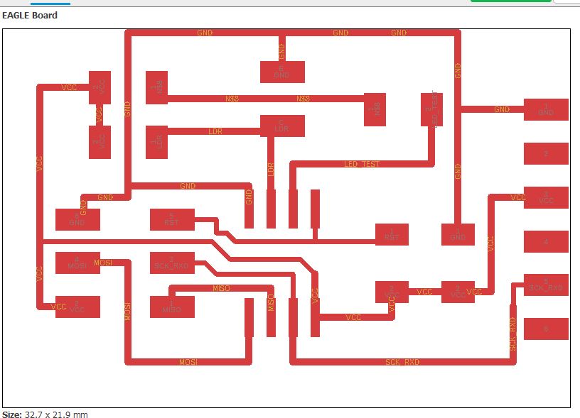
this is the final png for milling
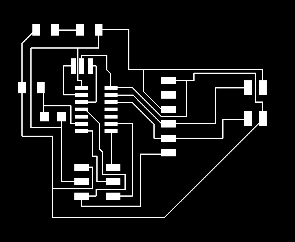
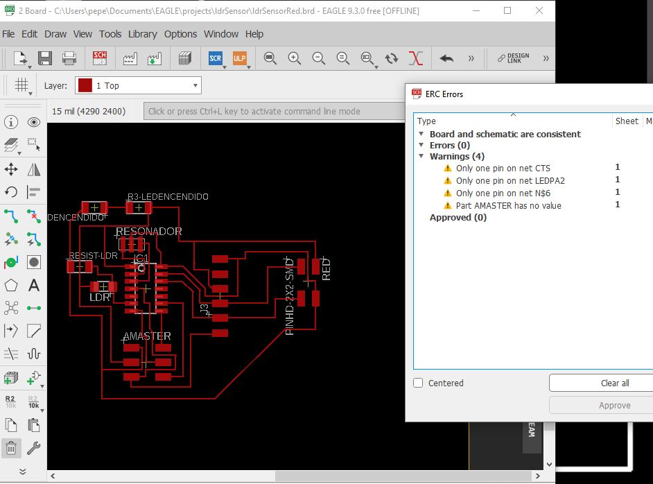
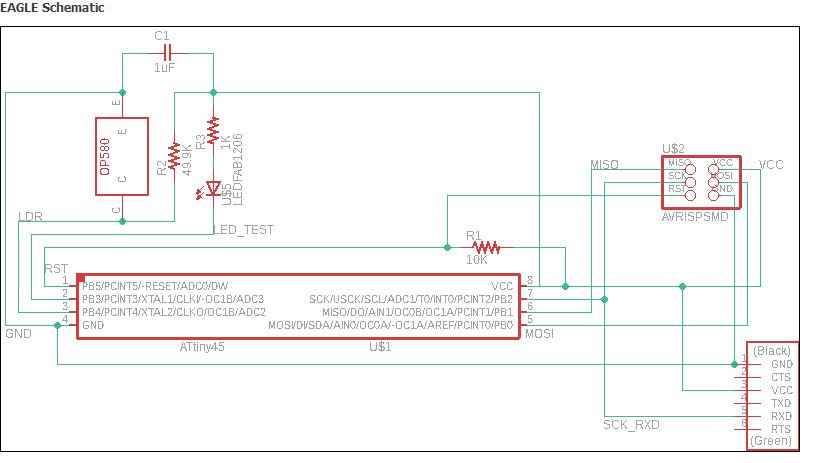
ERC TOOL:ERC is an eagle tool to detect possible connection errors and consistency on the board. Its use is very advisable to have a final idea of possible errors
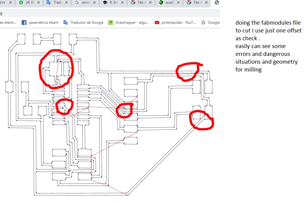
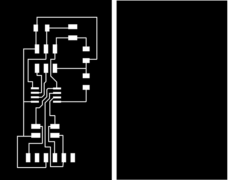
as always I first use fabModules with a single path, because that way we can better appreciate the possible defects in the trajectory of the drill.
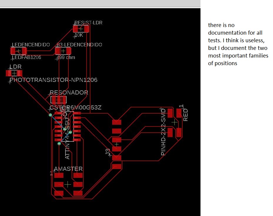
dangerous trajectorys are not appreciated that accidentally connect roads, but if some details of nearby trajectorys where attention should be paid.
so I decide to modify small details just for prevention, to have this final path for milling
STEP 2 : design and fabrication of servo network board
For the same reasons explained above, the board designed in previous assignments to control a servo (assignment output) is not valid, so design and mill a new one.
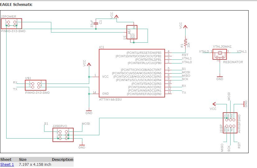
components in schematic
.JPG)
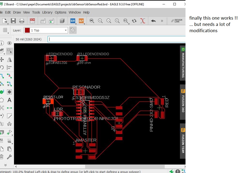
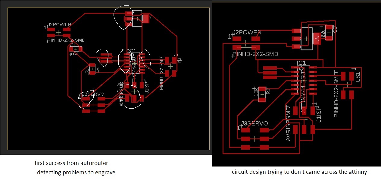
first design with lots of problems
In this first attempt you can easily see how there are some lines very close to the footprints of some components, once the line widths and the separation of these are adjusted. Thus, it is necessary to correct positions and the layout of some of these lines by hand. The most serious of all, of course, is the bridge marked in blue, it would be required to establish the connection on the back of the board..
.JPG)
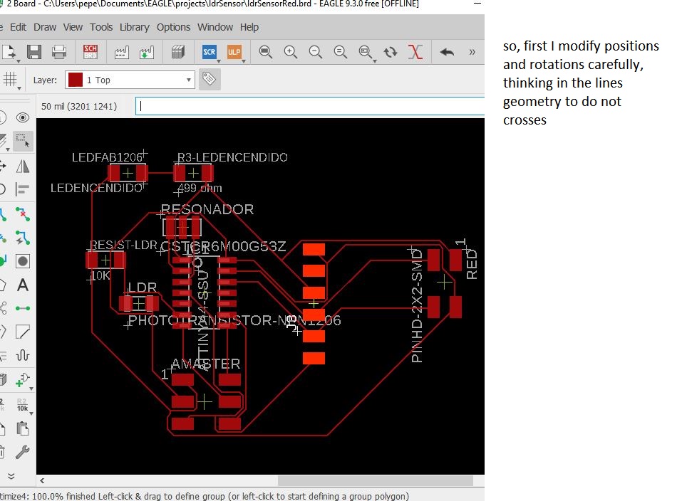
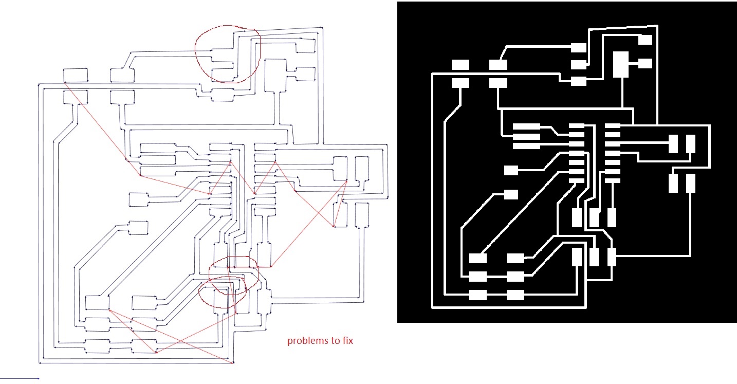
Second design with a line crossing under the attinny44 wich allways gave me problems
I have tried to solve it on other occasions by passing the line between the tracks of the attiny44, but I have almost always had errors in the layout and it has been necessary to repeat the board. So I decide to reserve this solution and opt for it only in the case of not finding another solution
.JPG)
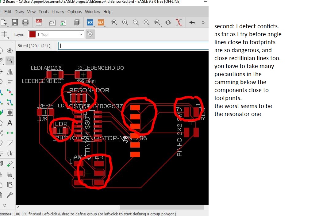
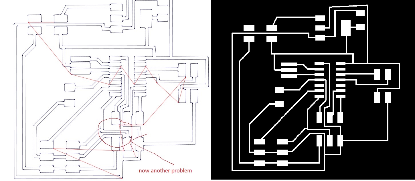
This seems to be the solution,although there would be several tweaks on hand to do. Try to avoid the footprint of the connections, make the line paths as straight as possible, access the component footprints perpendicularly, and separate the lines from the footprints whenever possible.
.JPG)
checking all using ERC tool
.JPG)
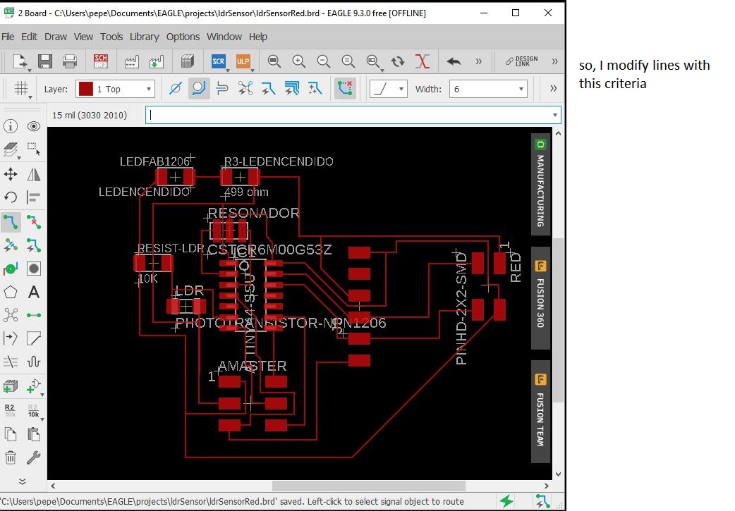
Hand made tweacks example :I modify some lines for the milling process taking care of distances to footprints
.JPG)
this seems to be good for milling
.JPG)
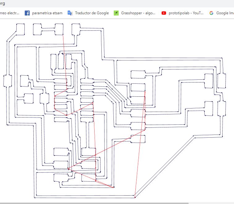
check in fabmodules with just one ofsset to see clearly any problems
.JPG)
result in fab modules for milling
.JPG)
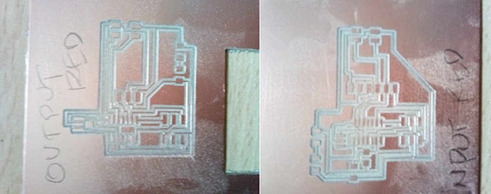
STEP 3 : MILLING BOARDS
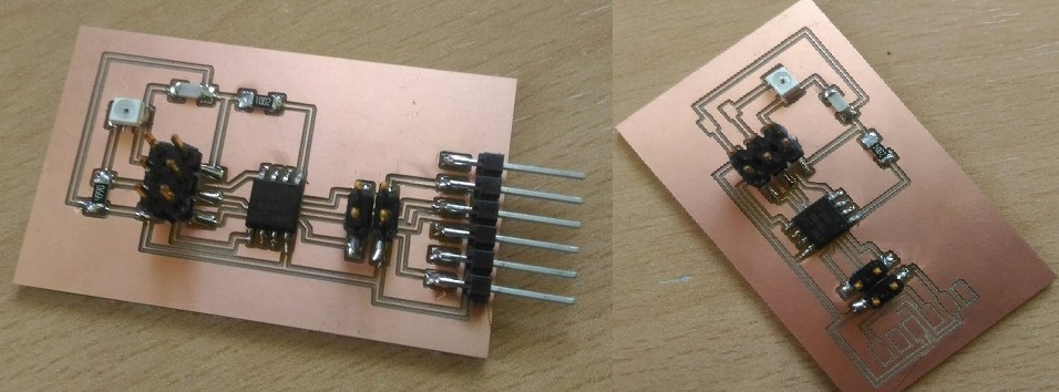
board engraving result
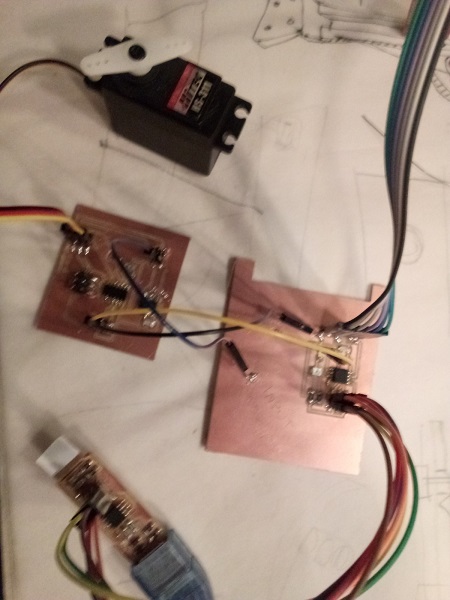
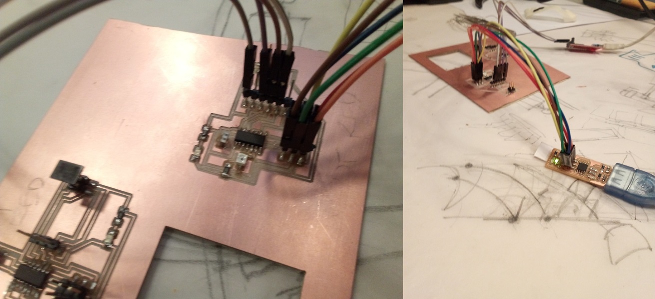
STEP 3 : COMPONETS SOLDERING AND CONNECTIONS
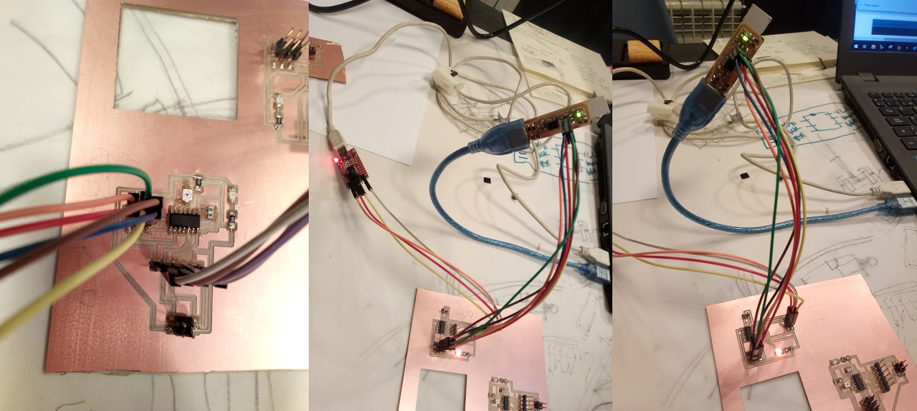
STEP 3 :PROGRAMMING BOARDS
different attempts of programming of the two boards.
The problems were:
Arduino IDE does not recognize the board.
error search protocol
--revision of the arduino IDE configuration. correct
--USB connection review (fails many times). The computer does not detect the boards.
--methodical review of connections between boards and with the
programmer.
Since this did not work: complete disconnection of the boards and check line by line with the polymeter.
No works
so I deduced that there was some error in the design of the plates.
As a solution I intend to design the boards from scratch again by going to different examples of my colleagues at fab academy in this and other years, trying to find new ways of such a design and adapt them to mine
STEP 4 : NEW BOARDS FROM SCRATCH
so same process for design and fabrication
the input one
png traces ready for fab modules
fab modules files for milling withs single offset check
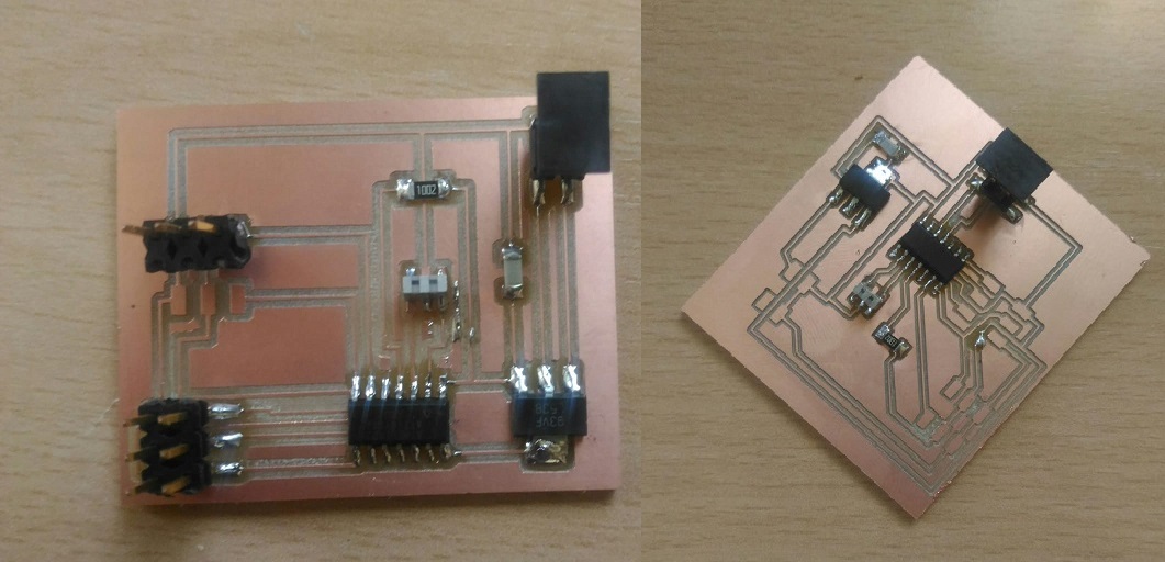
solderng components and final result
the output one
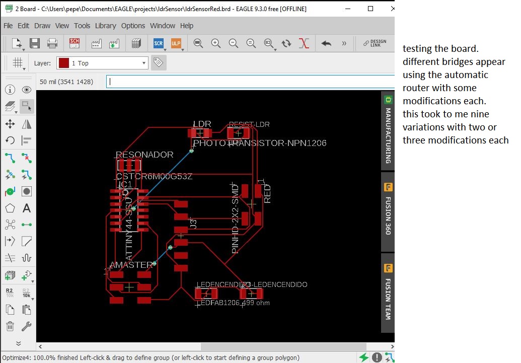
Now works in differents solutions with autorouter
In this process I find different solutions, although again and again I find the problem of passing lines between the fingerprints of the processor
finally I find a solution and check in fab modules with a single offset, because given the proximity of some lines I'm afraid of a problem
and indeed, although in the plot PNG everything seems correct fab modules detects that there will be problems in milling
after some manual corrections a new check detects another possible problem due to the proximity of the lines
It seems that in this solution the problem is solved. It is a risky solution due to the poor condition of the bits, but I decide to continue
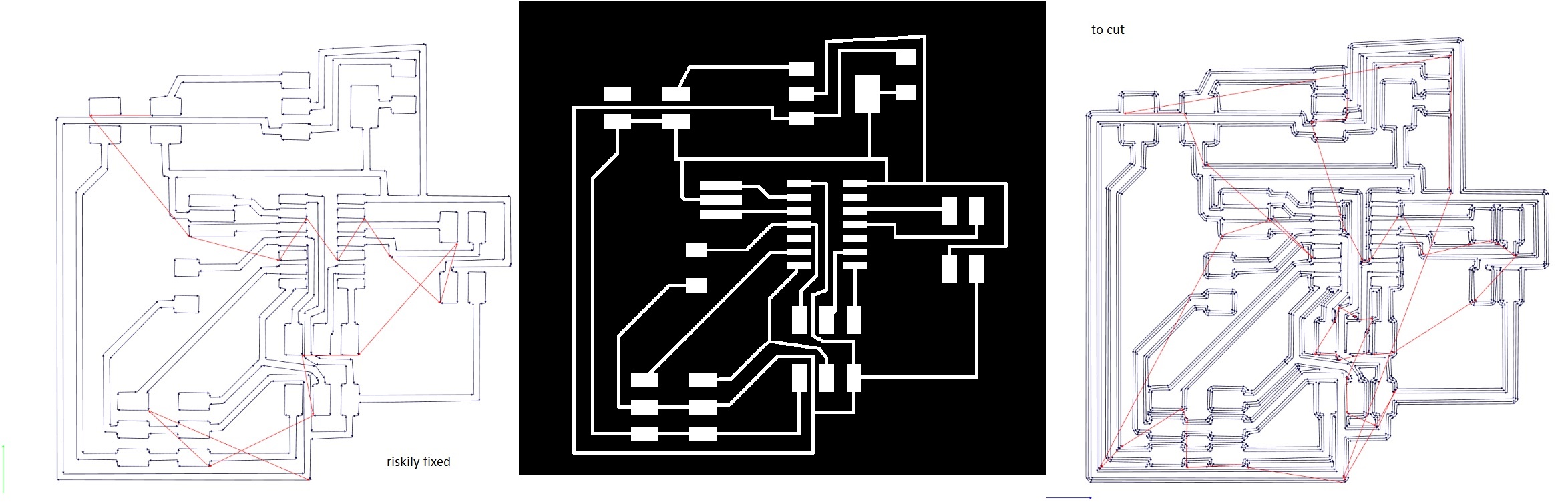
fab modules files to cut the board

solderng components and final result
STEP 5 (UPDATE): UNDERSTANDING THE SERVO CODE AS DEEP AS I CAN
Following the instructions of my global instructor about the code to be developed, I revisit the neil code to move a servo, in order to understand how it behaves
//
// Neil Gershenfeld
// 4/8/12
#include 'avr/io.h'
#include 'util/delay.h'
// What this macro does is apply an OR (|) function between directions and pin. This is used to set a pin to 1.
// This is done because the
directions register address that indicates the digital status of the pins.
// So if the record says 00000000 and you want to put pin 3 high, you have to make a door
// OR with the value 00100000. To know what is the value to use, in
the datasheet you have to
// look for the description of that record.
#define output(directions,pin) (directions |= pin) // set port direction for output
// Do the same as the previous one
#define set(port,pin) (port |= pin)
// set port pin
// This macro does the opposite, if the register indicates that this pin is at a high level, making a door
// AND (&) with the opposite of the pin value, with a NOT (~) operation, so if pin 3 is
// 00001000, when
NOT is applied 11110111. And then the AND function is applied: 00001000 & 11110111 = 00000000
#define clear(port,pin) (port &= (~pin)) // clear port pin
// What this macro does is detect if pins and pin have the same value, if so it
stays the same, if not
// the result is 0
#define pin_test(pins,pin) (pins & pin) // test for port pin
// same idea as the previous one
#define bit_test(byte,bit) (byte & (1
<< bit)) // test for bit set
// wait one second
#define position_delay() _delay_ms(1000)
// To use a pin you always have to turn on the port first and then the address,
// This is because inside the hardware the pins are separated by ports.
// // PORTA
- this is the Port A Data Register
// PORTA7|PORTA6|PORTA5|PORTA4|PORTA3|PORTA2|PORTA1|PORTA0
// initial value: 00000000
#define PWM_port PORTA
// To have a 1 in the position where you need, in this case use the 1 that
in binary is 00000001
// As PA3 = 00000011 = 3, whereby the operator
<< moves the bits of the value on the left so many
// times as indicated by the value on the right. In this case it would be 00000001
<< 3=0 0001000
#define PWM_pin (1
<< PA3)
// PORTA - is the Port A Data Direction Register
// DDA7|DDA6|DDA5|DDA4|DDA3|DDA2|DDA1|DDA0
// initial value: 00000000
#define PWM_direction DDRA
... and the main code allready commented in the output assignement
STEP 6 : UNDERSTANDING WHAT NETWORK IS
In the search for information and in the data provided by Neil you can realize that there are many network communication protocols. So I go to several sources to know what it is, different types and rules, advantages and disadvantages of each, and their fields of application
tech target some definitionswikipedia protocols
interserver protocols and applications
lifewire protocols explained
science direct network protocols
after some reviews I decided to go deep in two protocol possibilities I2C and SPI
REVIEWING i2c PROTOCOL
based in this instructions and information...
CIRCUIT BASICSI realize that this protocol is quite suitable when communicating a microcontroller with many others considered slaves.
I2C is a serial communication protocol therefore the data is transferred BIT A BIT along a single cable.
I also note
that the same as SPI I2C is synchronous so that the output information is synchronized with the processor clock. clock is controlled by the BOARD MASTER.
As I see in this analysis
BUS I2C ARDUINOthere is some advantages and disadvantages for this protocol
ADVANTAGES
It requires few cables
It has mechanisms to verify that the signal has arrived
DISADVANTAGES
Its speed is medium-low
It is not full duplex
There is no verification that the content of the message is correct
The I2C protocol is used through the Wire library, which is implemented as "#include
This library contains a few basic functions for data transmission.
--- for transmission (master)
Wire.begin (); // join i2c bus (address optional for master)
Wire.beginTransmission (4); // transmit to device # 4
Wire.write (x);
// sends one byte
Wire.endTransmission (); // stop transmitting
---- for reciving (slave)
Wire.begin (4); // join i2c bus with address # 4
Wire.onReceive (receiveEvent); // register event
Wire.available ()
Wire.read ()
that would be exactly what I need to transmit my data
but looking for some application examples I found
USING I2C ON ATTINNY85where I can read "The standard Arduino library cannot be used for I2C on the Attiny because it does a call to 'Wire.h' and that one is not compatible with the Attiny" literally
so I need to check SPI protocol
REVIEWING SPI PROTOCOL
Serial Peripheral Interface (SPI) is a very similar protocol developed by motorola
with similar functions like
#include
SPISettings settingsA(x, x, x); // setting the communication
SPI.begin(); // inicialization
SPI.beginTransaction(settingsx);
SPI.transfer();
SPI.endTransaction(); //recommended not to interfere with other libraries
But, as I can read in
ARDUINO SPI LIBRARY"this library supports only master mode"
so I cant use it in my proyect
USING UART Based Networking for Microcontrollers
After weighing the advantages and disadvantages of the different network protocols reviewed, I consult similar examples carried out in fab academy to get an idea of how to use a protocol, the advantages and disadvantages of each in the different projects and results and find the best way to adjust it to my project
eduardo segovia jose fuenzalidafablabegypt
nikita-kovalchuk
gustavo deabreu
anton-pchelkin
ivan-avado
mayra-lopez
The solution came discovering the UART network for microcontrollers used by the SoftwareSerial.h library, much lighter, which also allows me to label devices in a propper network.
so I decided to learn about and use this to operate
from wikipedia :
A universal asynchronous receiver-transmitter (UART ) is a computer hardware device for asynchronous serial communication
in which the data format and transmission speeds are configurable.
The electric signaling
levels and methods are handled by a driver circuit external to the UART.
A UART is usually an individual (or part of an) integrated circuit (IC) used for serial communications
over a computer or peripheral device serial port.
The first question to understand, since it appears on all the websites consulted, is the difference between serial communication and parallel communication.
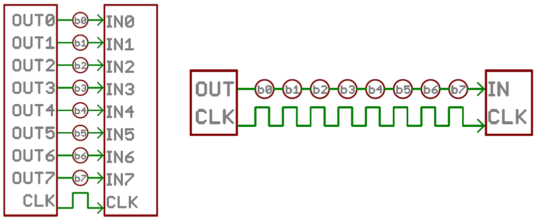
in this example as parallel An 8-bit data bus, controlled by a clock, transmitting a byte every clock pulse. 9 wires are used.
meanwhile in an example of a serial interface, transmitting one bit every clock pulse. Just 2 wires required!
from MIKROESo serial communication is the process of sending data one bit at a time, sequentially
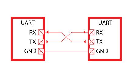
The communication goes through the two independent lines : TX (transmission) and RX (reception).
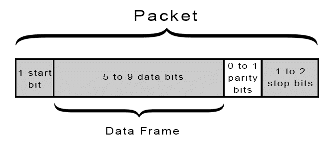
UART transmitted data is organized into packets. Each packet contains 1 start bit, 5 to 9 data bits (depending on the UART), an optional parity bit, and 1 or 2 stop bits:
from circuit basicssee more in webs
sparkfunelectric imp
geekytheory
aprendiendoarduino
So I use the softwareSerial library for my network using the code included in the arduino web as an application example and some other examples from fab academy
software serial examplecode commented . complete code included in download files
ldr sensor code
#include "SoftwareSerial.h"#define address_1 1 // label
const int analogInPin = A2;
int sensorValue = 0;
int outputValue = 0;
const int Rx = 1; // this is pin 7
const int Tx = 2; // this is pin 6
SoftwareSerial mySerial(Rx, Tx);
void setup()
{
// pin configuration
pinMode(3, OUTPUT);
pinMode(Rx, INPUT);
pinMode(Tx, OUTPUT);
mySerial.begin(9600); // send serial data at 9600 bits/sec
}
void loop()
{
// read the sens
sensorValue = analogRead(analogInPin);
// map it
outputValue = map(sensorValue, 0, 1023, 0, 255);
//mySerial.print("sensorValue = ");
mySerial.print(outputValue);
mySerial.write(address_1);
// sensor conditions to send a signal
if(outputValue > 240)
{
digitalWrite(3, LOW);
}
else
{
digitalWrite(3, HIGH);
}
delay(15);
}
servo code
#include "Servo.h"#include "SoftwareSerial.h" //load serial library
const int Rx = 1; // this is pin 7 input
const int Tx = 2; // this is pin 6 output
SoftwareSerial mySerial(Rx, Tx);
#define servo 3 // the PWM pin the servo is attached to
#define address_1 1 // label
int bytein = 0; // for incoming serial data
//variables
int pinServo = 3; //revisar para ver el pin
Servo motor; //Servo as an object
int sensor; // sensor values
void setup (){
mySerial.begin(9600); //comunicación entre el puerto serial y el arduino
motor.attach(pinServo); //vinculamos el servo al pin
}
void loop (){
if(mySerial.available()>=1)
{
int addressbyte = mySerial.read();
if (addressByte == address_1)
{
motor.write (sensor); // servo moving with sensor values
Serial.println (motor.read()); //servo position
delay (2000); // intervalo de 2 seg
}
}
}
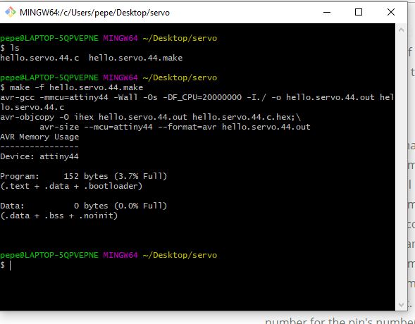
console program testing one servo
the make -f hello servo
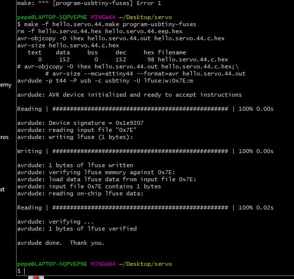
the program usb tinny fuses
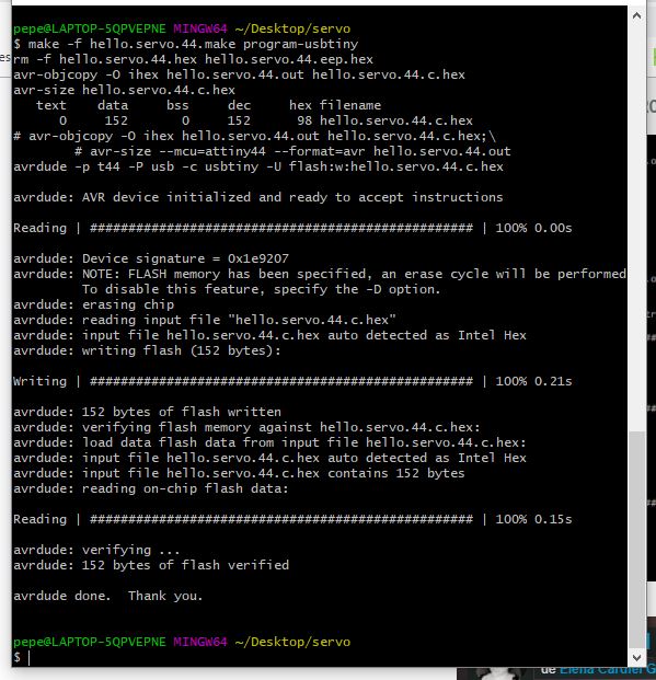
the writting flash
and this this is the console program testing two servos
p> the make -f hello servo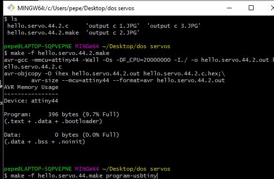
the program usb tinny fuses
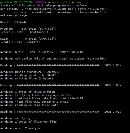
network connexions