 FabAcademy 2019
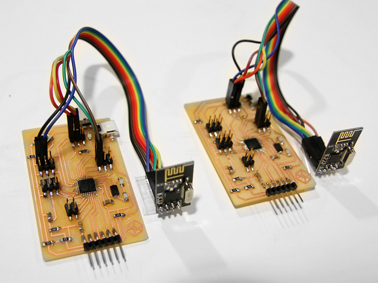
Networking and Communications
1. Group Assignment
Send a message between two projects
1.1Send a message between two projects
Carlos Nina. - Ivan Callupe.
Diego Santa Cruz.
Team Group
For this assigment we used Carlos and my board to communicate. Using Software Serial we will sending signal through a button push. Code for this next:
_
Code for this next:
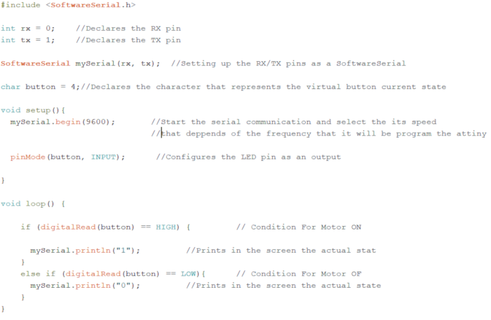
Button board code:
_
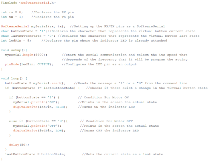
LED board code:
_
We set the Arduino IDE parameters for using it as a programmer. This parameters are for a Attin44 microcontroller:
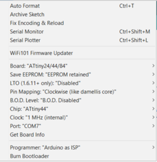
_
Now the parameters for a Attiny45 microcontroller:

_
Once burned, we test it. We are using a Arduino One board to power it:
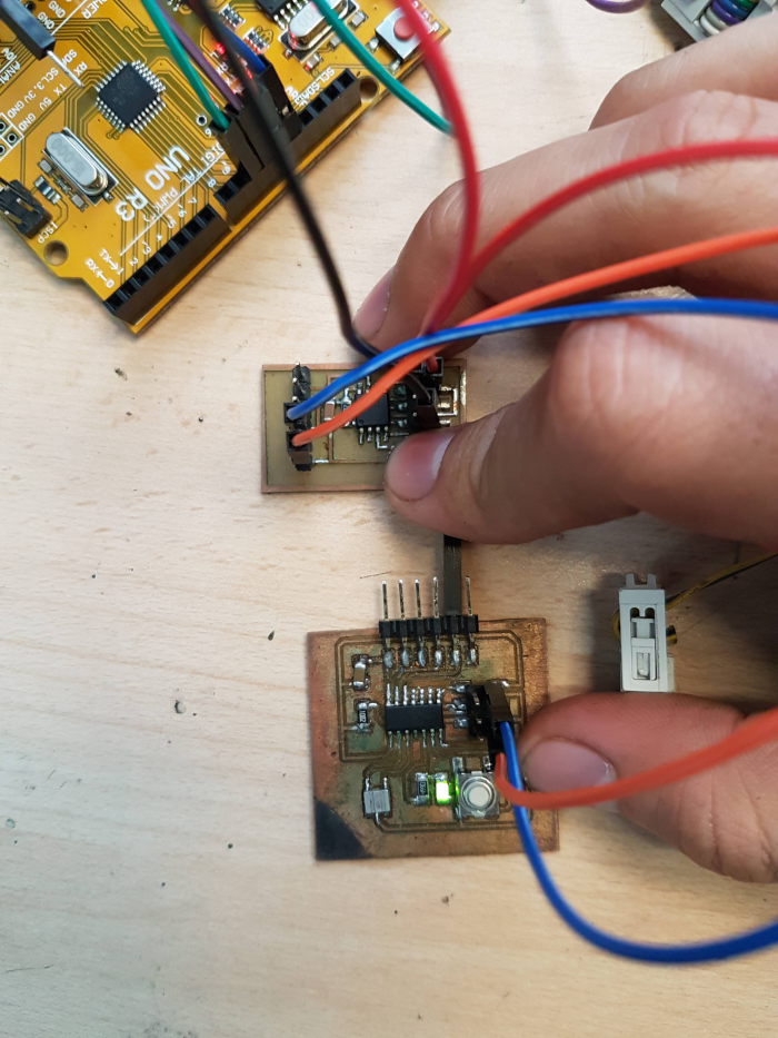 It works!
It works!
It works!
2. Individual Assignment
Design, build, and connect wired or wireless node(s) with network or bus addressese
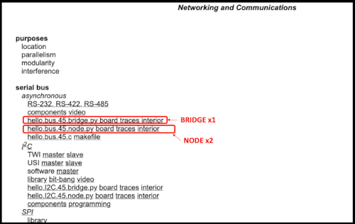
2.1 Serial Bus
Data transmission refers to the process of transferring data between two or more digital devices. Data is transmitted from one device to another in analog or digital format. Basically, data transmission enables devices or components within devices to speak to each other
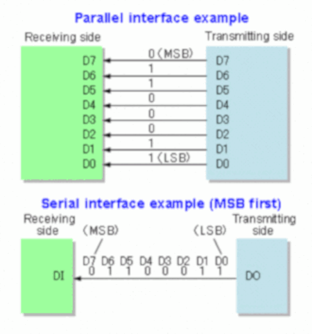
Data is transferred in the form of bits between two or more digital devices. There are two methods used to transmit data between digital devices: serial transmission and parallel transmission.
When data is sent or received using serial data transmission, the data bits are organized in a specific order, since they can only be sent one after another. The order of the data bits is important as it dictates how the transmission is organized when it is received. It is viewed as a reliable data transmission method because a data bit is only sent if the previous data bit has already been received.(
When data is sent using parallel data transmission, multiple data bits are transmitted over multiple channels at the same time. This means that data can be sent much faster than using serial transmission methods.
_
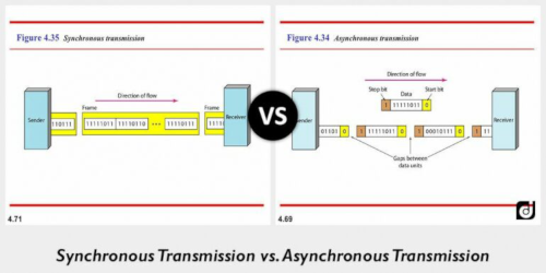
Data bits can be sent at any point in time. Stop bits and start bits are used between data bytes to synchronize the transmitter and receiver and to ensure that the data is transmitted correctly. The time between sending and receiving data bits is not constant, so gaps are used to provide time between transmissions.
Data bits are transmitted as a continuous stream in time with a master clock. The data transmitter and receiver both operate using a synchronized clock frequency; therefore, start bits, stop bits, and gaps are not used. This means that data moves faster and timing errors are less frequent because the transmitter and receiver time is synced. However, data accuracy is highly dependent on timing being synced correctly between devices. In comparison with asynchronous serial transmission, this method is usually more expensive.
_
2.1.1 Making PCB Boards
FFor the assignment this week, I used the schemes provided by the FabAcademy..(
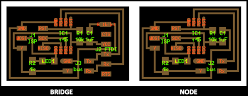
_
The scheme of the BRIDGE and NODES boards
_
The traces and the interior of the BRIDGE board.
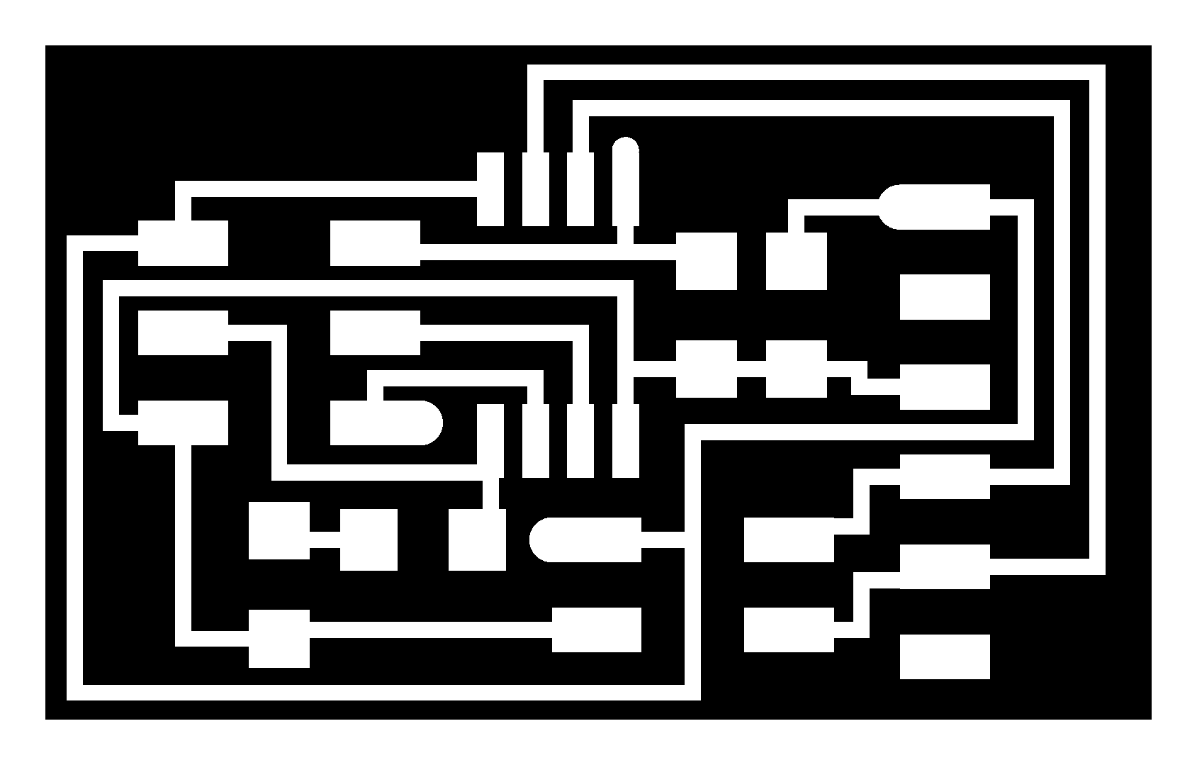

_
The traces and the interior of the NODE boards.
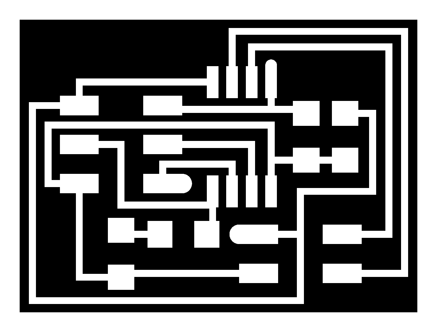

_
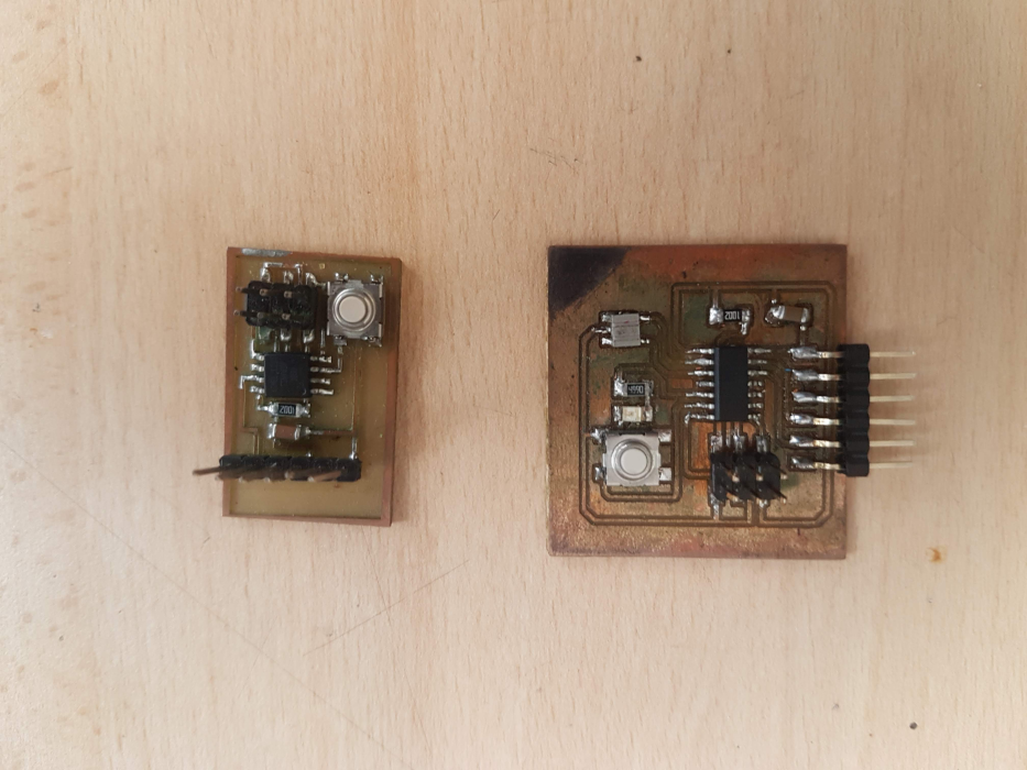
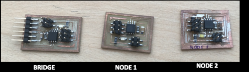
BRIDGE and finished NODES boards:
_
2.1.2 Programming Bords
For the programming of boards it is necessary to download the file "
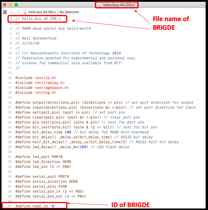
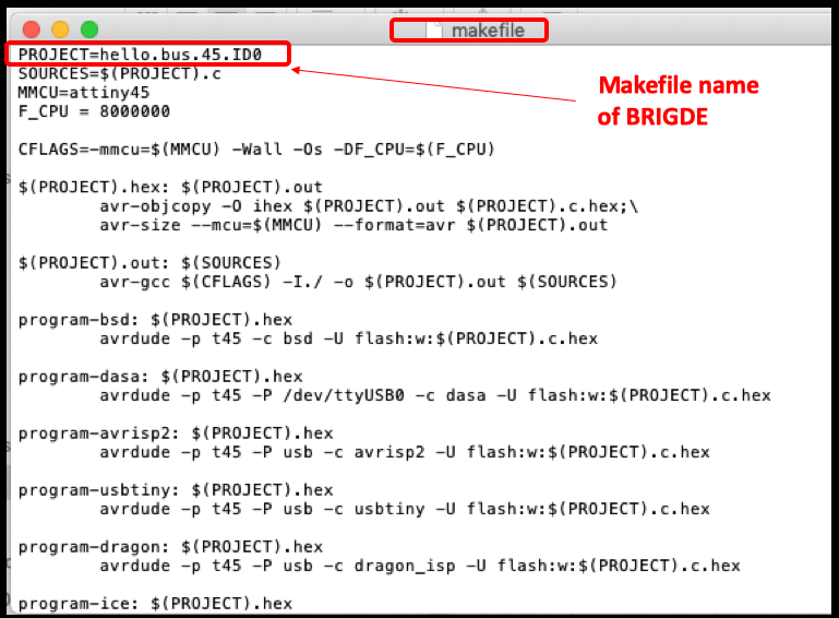
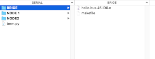
For the BRIDGE board we must name it with a name (hello.bus.45.ID0) and node ID number (ID 0). Also the file make file contain the designated name:
_
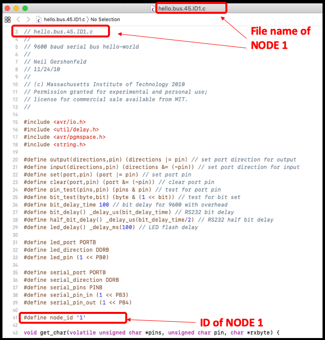
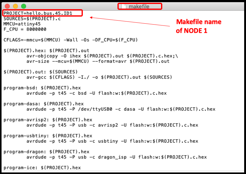
For the NODE 1 board we must name it with a name (hello.bus.45.ID1) and node ID number (ID 1). Also the file make file contain the designated name:
_
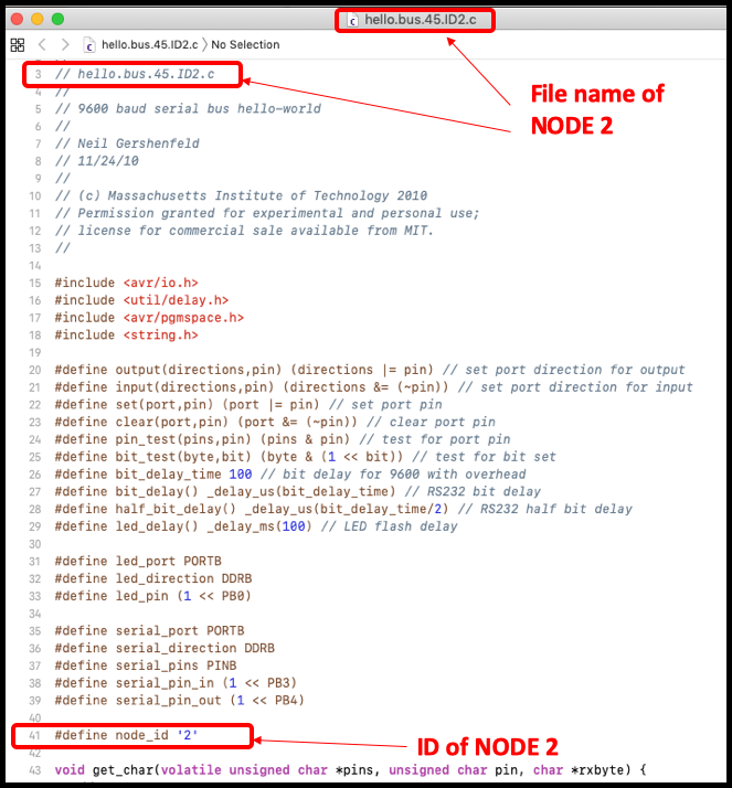
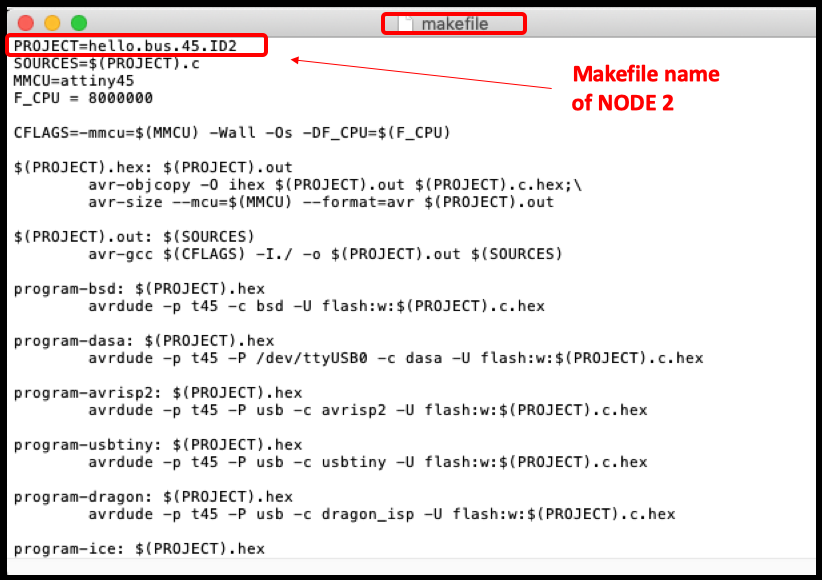
For the NODE 2 board we must name it with a name (hello.bus.45.ID2) and node ID number (ID 2). Also the file make file contain the designated name:
_
It is recommended to save both files in folders named BRIGDE and NODES.
_
To program the boards, it is necessary to use a programmer type "ISPTiny".
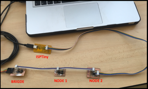
$ sudo make program-usbtiny (Your programmer)
2.1.3 Results
To verify serial communication. I used the
$ sudo python term.py /dev/cu.usbserial-FTFOYQZS 9600
SELF EVALUATION
WHAT WORKED:
- I probe with a output device.
- I verified the connection characteristics of output device.
- I used an interface, where I could see through the computer how these motor act.
WHAT DID NOT WORK:
- I could not try other types of output device. Because we did not have available in the lap or why they need to make another electronic bord.
THINGS TO IMPROVE:
- Control my time.
- Learn more about the operation of other types of output device. That will be useful for my final project.
Contact Me
Feel free to contact me via email or phone.