embedded programming
individual assignment :Read a microcontroller data sheet.


UPDATE: fuses
Members of the AVR family may have one or more Fuse Bytes. How many there are, and what they do, depends on the specific microcontroller
Reading the datasheet for AVR micros, with a "1" means that it is not programmed while a "0" is considered
to be programmed
following the tutorial ( link below) I used avr fuse calculator just to know more about fuses
avr fuse calculator
which shows this default configuration


eleccelerator UPDATE:clock
as I read in datasheet the chip contains four different clocks:
the CPU Clock,
the I/O Clock,
the Flash Clock
and the ADC Clock.
The internal oscillator is the default clock and it runs at 8mHz
External Clock means that
a square wave is being input into the CLOCK-IN pin. This is pretty rare unless you have a clock generating chip. (from the link below)
Internal Clock means that theres a little oscillator inside the chip, its not very precise but good
for most projects that dont have fine timing issues.(from the link below)
in this case we use External Crystal (oscillator)
we use a clock rate (20MHz) and that won't drift with the temperature

tutorial where I found information about fuses and external clocks
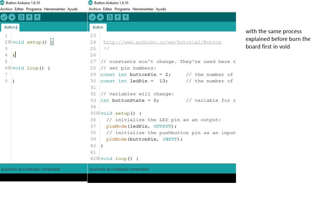
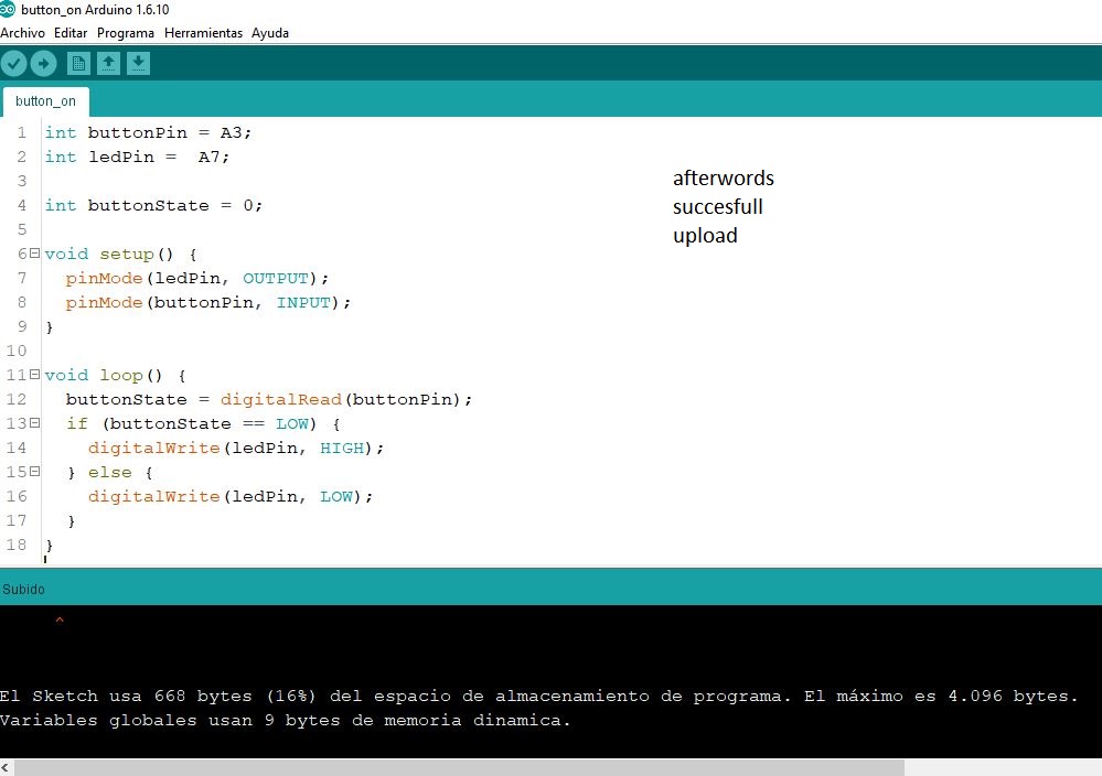
individual assignment : Program your board to do something


.jpg)


ftdi connection can be used as cable or driver.
As seen in the pictures I use driver type.
The FTDI DRIVER is a Série-USB (TTL) converter that allows you to connect TTL devices via USB.
The driver is configured to operate at 5V.
The available pins are: RTS, RX, TX, 5V, CTS, GND (RTS is green and GND is black).
.JPG)
.jpg)
.jpg)
.jpg)
.jpg)
.jpg)
.jpg)


reconstructed board connexion and programming
.jpg)
.jpg)
.jpg)
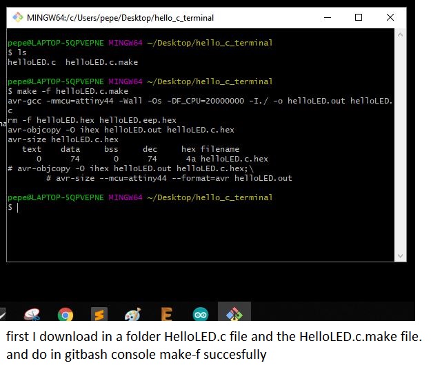
using c

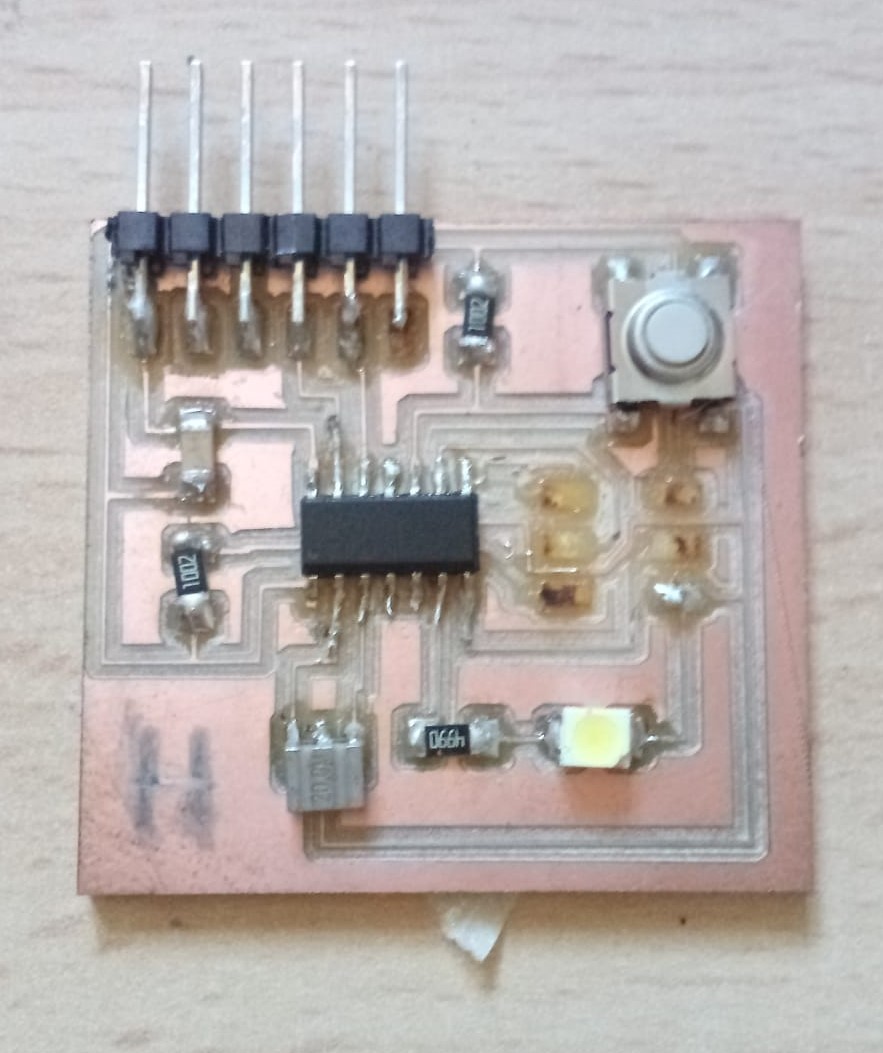
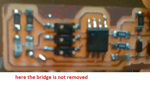
Unfortunately after the first test and disconnecting the board the entire ISP connection flew through the air ripped out.
if you find some documentation failures in the board manufacturing process please go for a complete process to the assignment 11 "output new board"
see complete process input board see complete process output board see complete process network boards