output
UPLOADindividual assignment :Add an output device to a microcontroller board you’ve designed, and program it to do something..
The purpose of this assignment is to understand what is a pulse (PWM) and how it works.
To use a pWm pulse I will control a servo motor with the corresponding commands
At first I thought that the best way to approach the design of this circuit was to start with a board that I already knew. That way I thought that what I would need would be to add a PWM port to connect the servo motor and ideally communicate with it via serial so I can program it from the Arduino interface.
UPDATE: Much later and by indications of Eduardo Chamorro (fab lab barcelona) I learned that this circuit could never get to work. Apparently the attinny44 processor does not have enough memory to host the servo library and serial communication, so this circuit would only be possible using attiny 88 processor that we did not have available at that time.Therefore, the only viable solution would be to suppress the serial connection and program the servo directly without a library
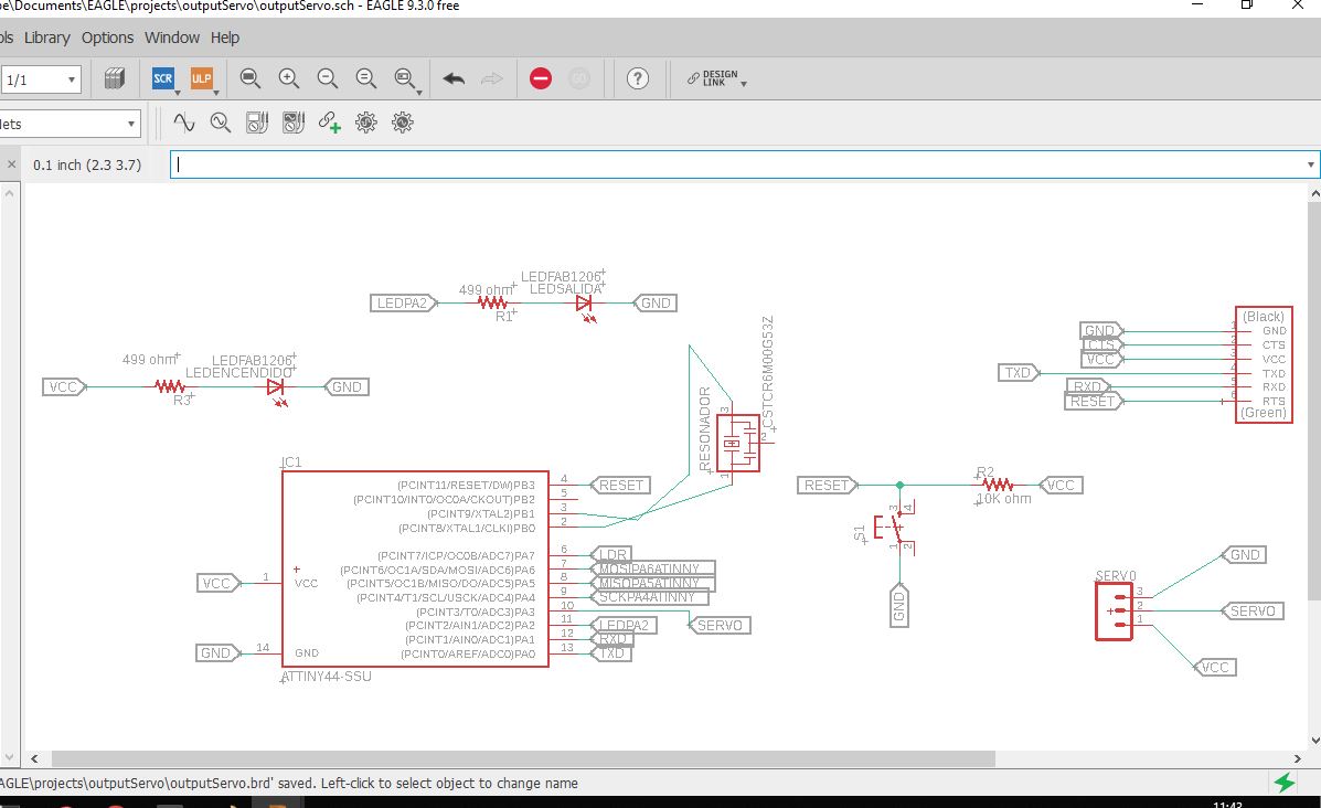
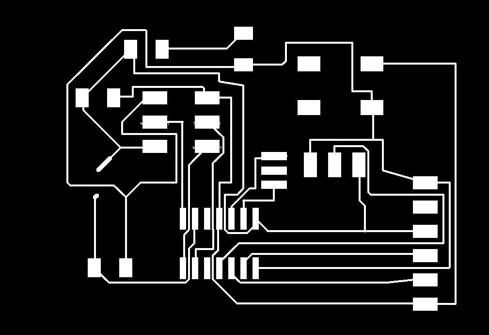
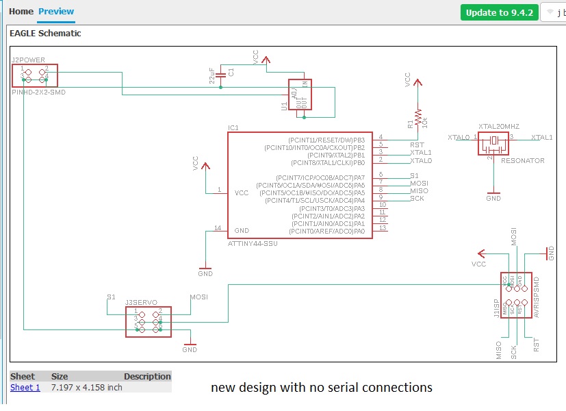
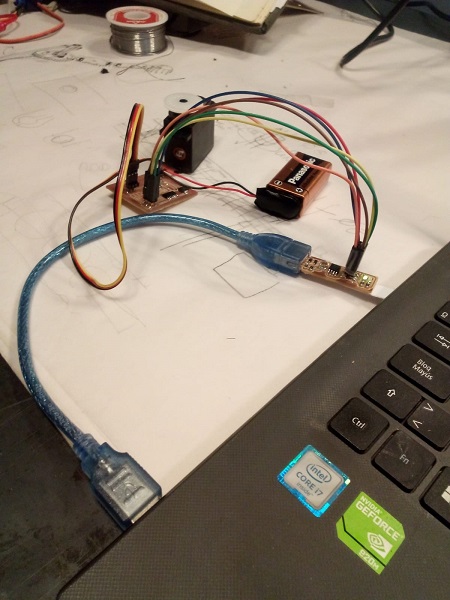
This is the first design of the circuit that tried in which was integrated both the LDR sensor and a connector for the servo. The idea was to make the LDR sensor move the motor depending on the values it transmitted.
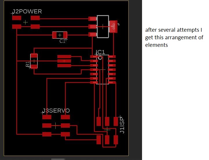
The problem was very difficult to solve although I only realized later. When starting from a board that already had and adding the necessary components to use a servo there were a lot of components that were not necessary and they made the design of circuit lines very difficult
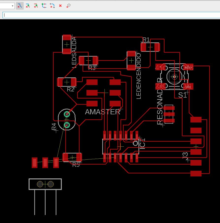
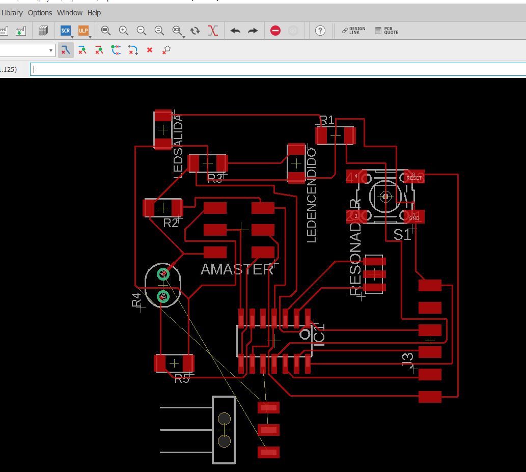
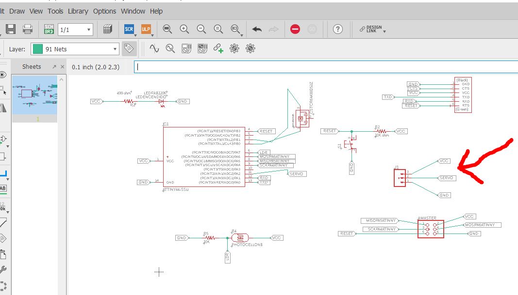
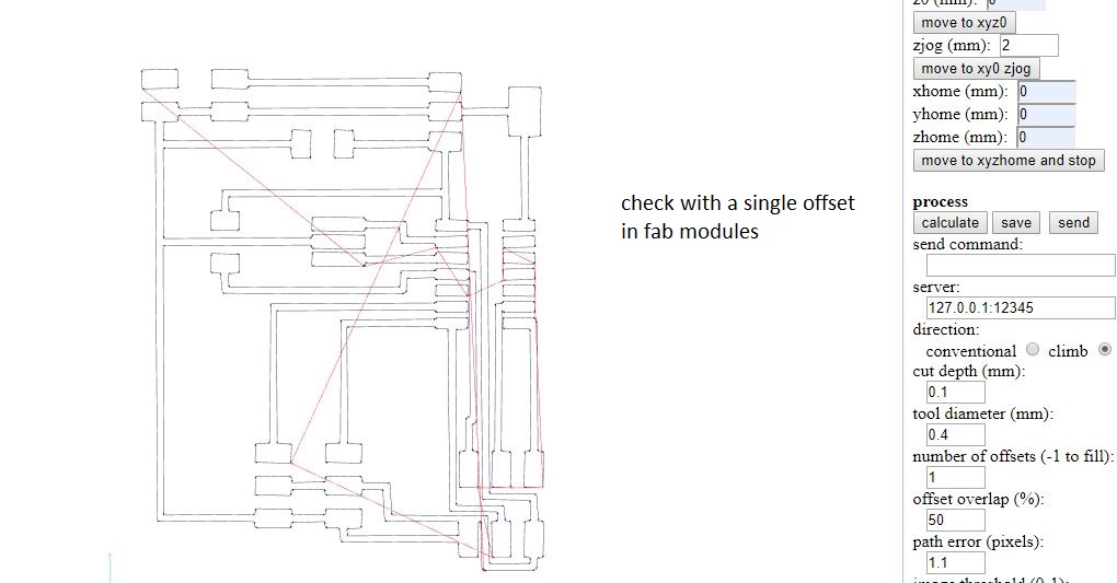
here a practically unsolvable problem in the connection the servo in its insertion in the circuit
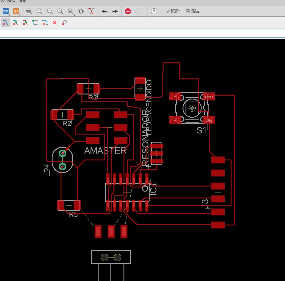
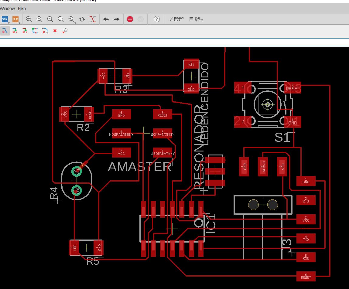
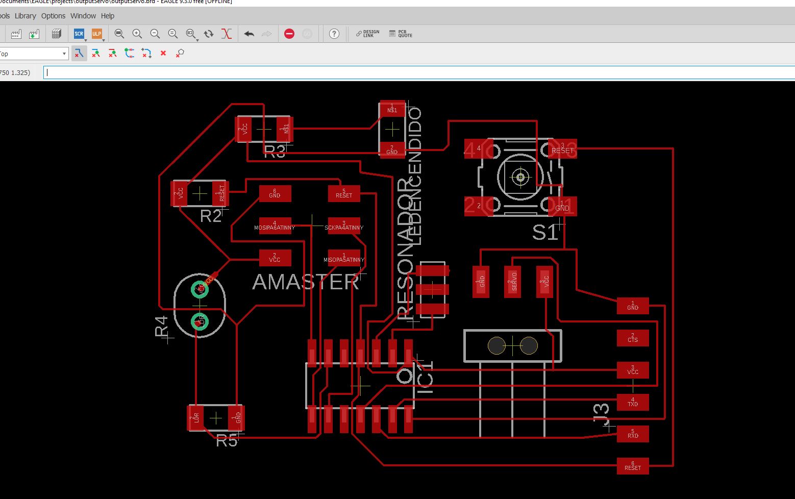
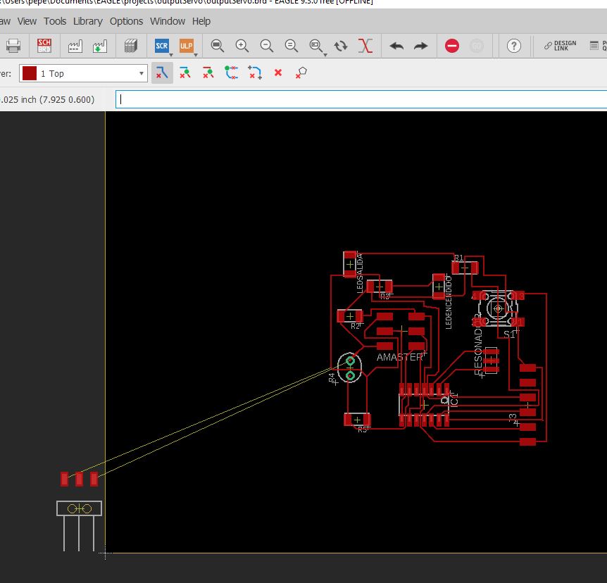
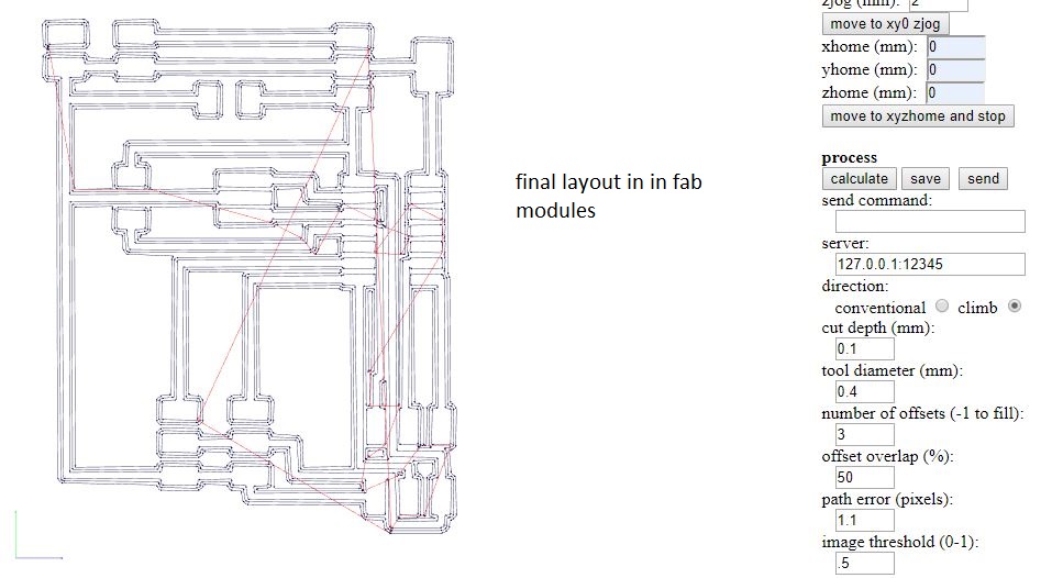
after many attempts a solution that nevertheless had some dangerous parts in the drawing of the lines when passing the diagonal very close to the footprint of the servo connector
.jpg)
.jpg)
output new board
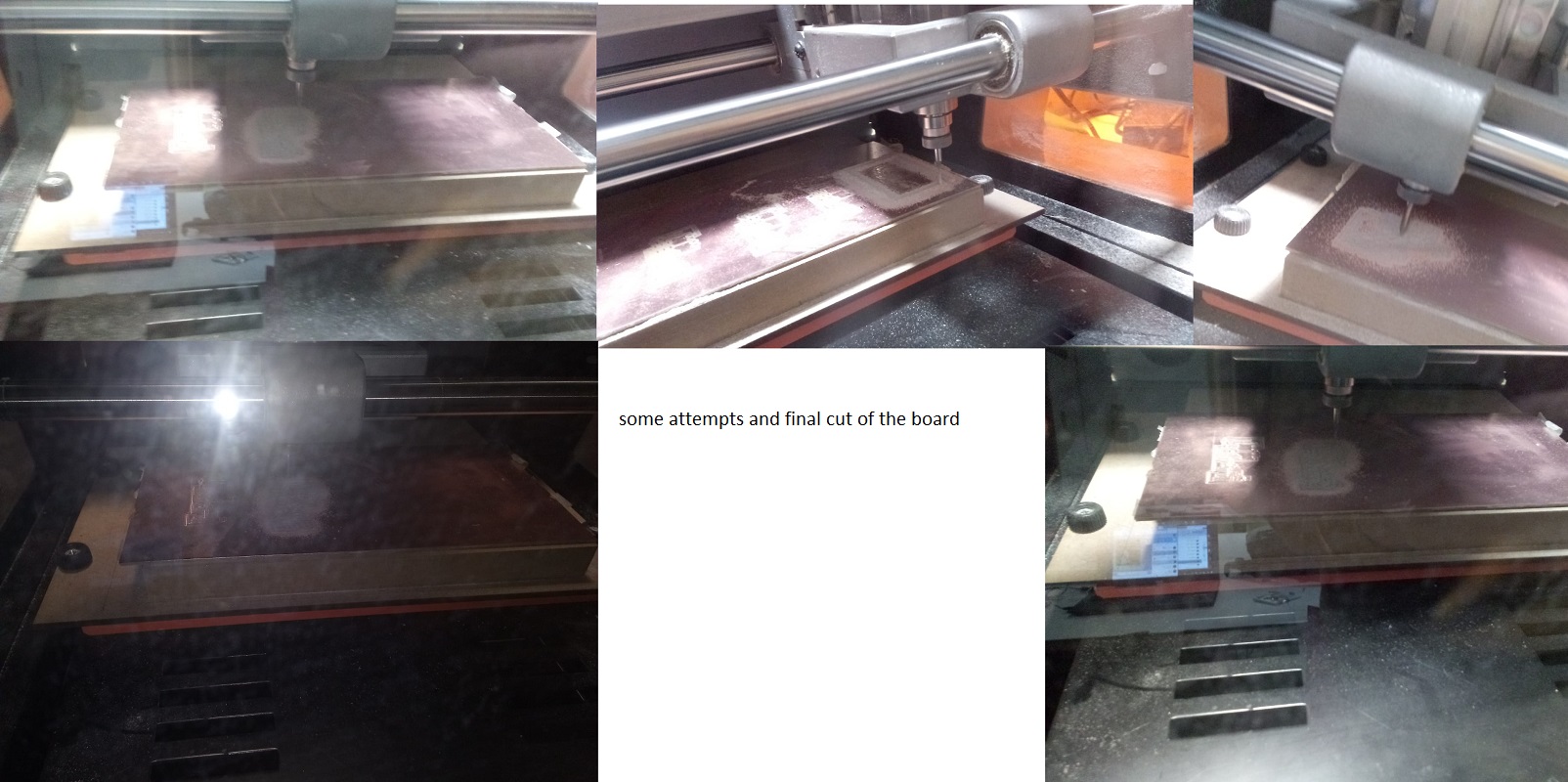
since I can not find the error, and already thinking about the final project, I try a new design for two servos
having failures in the documentation of the complete process of the making of a board in previous assignments I use this new design to document step by step
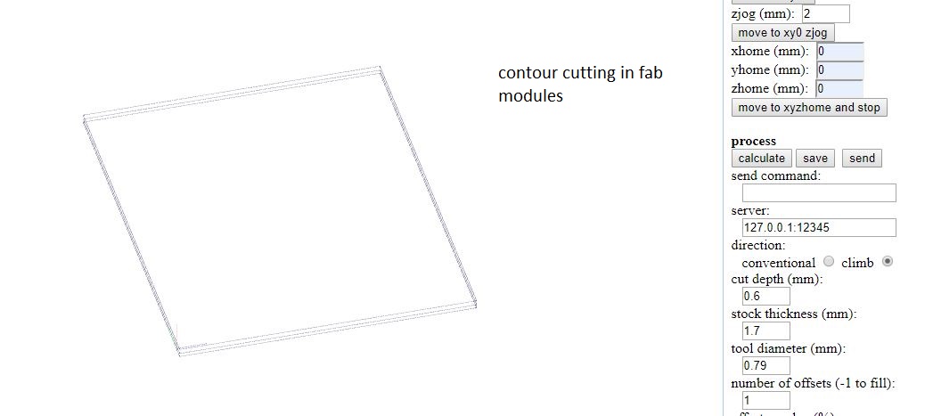
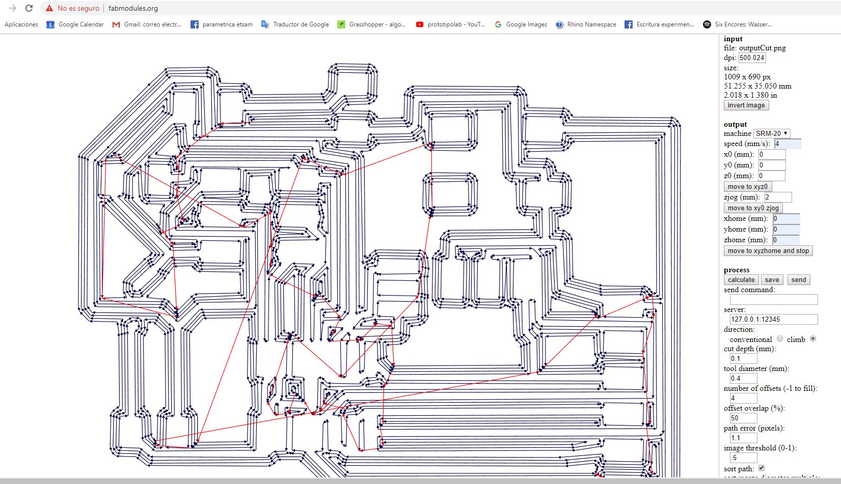
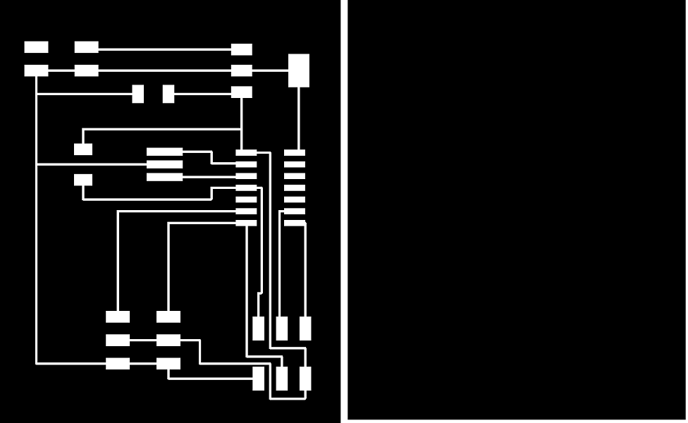
here the png
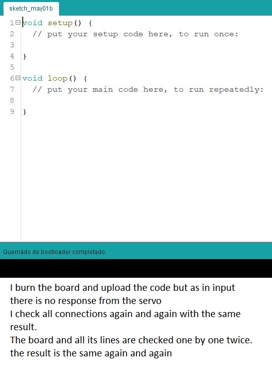
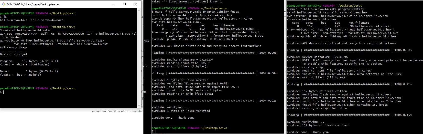
console screens for make, fuses and writing flash
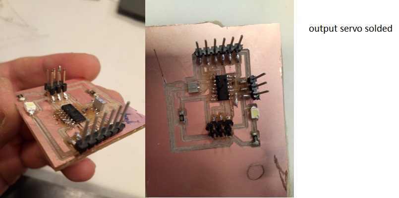
here the connections
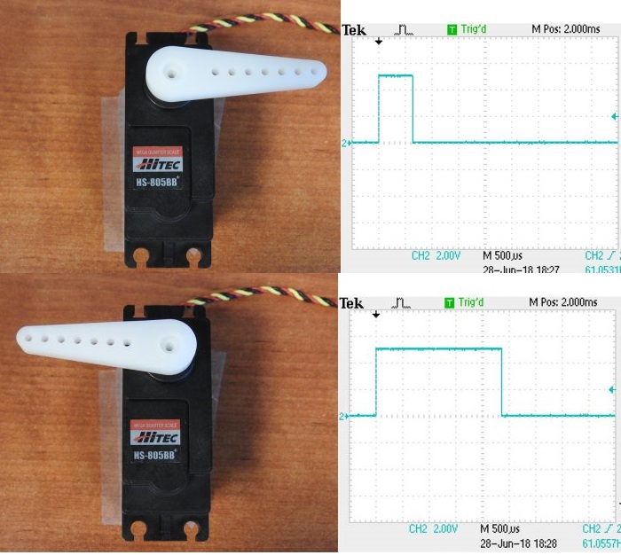
here the servo working
two servos working
UPDATE :understanding the code This code has as fundamental tasks set the fusses of attinny and send movement signals to the servo.
These signals are sent in PWM mode.
We talk about the PWM function as an abbreviation for pulse width modulation.
Pulse width modulation is formed by a square wave signal that does not always have the same relationship between the time that is high and the time that is low.
The time that the signal is at the high level (5 volts) we call it as time on (Ton) while the time that is at the low level we call it time off (Toff). The sum of the time on and the time off is the period of the signal (T).
And as in any periodic signal, the inverse of the period (1 / T) is the frequency of the signal.
By varying its voltage value between two known values,
for example Vcc and GND in specific periods of time and with a fixed frequency.
The variation in pulse width consists in varying the on and off times, that is, Ton and Toff. By changing the value of a PWM, these times are actually being modified. This is called duty cycle. So this is the relationship between the time at which the signal is sent (on) and the total period DC = Ton / T
So we are using the microcontroller clock to vary these pulses and send them as a signal.
reference information for PWM from barrgroup.com
UPDATE :code explained
because it is the first time I front c in this way I start from the code of Neil Gershenfeld trying to learn how it is built and how each line of code works
// Neil Gershenfeld
#include avr/io.h
The AVR Libc package provides a subset of the standard C library for Atmel AVR 8-bit RISC microcontrollers
this is an utility library for c
#include util/delay.h
// pin declarations
#define output(directions,pin) (directions |= pin) // set port direction for output
#define set(port,pin) (port |= pin) // set port pin
#define clear(port,pin) (port &= (~pin)) // clear port pin
#define
pin_test(pins,pin) (pins & pin) // test for port pin
#define bit_test(byte,bit) (byte & (1
<< bit)) // test for bit set
#define position_delay() _delay_ms(1000)
#define PWM_port PORTA
#define PWM_pin (1
<< PA3)
#define PWM_direction DDRA
in this block of code, what is the execution block, different parameters are set for the timmer control and we select the port to which the servo motor (PWM) will be connected
int main(void) {
// set clock divider to /1
//
CLKPR = (1
<< CLKPCE);
CLKPR = (0
<< CLKPS3) | (0 << CLKPS2) | (0 << CLKPS1) | (0 << CLKPS0);
//
// set up timer 1
//
TCCR1A = (1
<< COM1A1) | (0 << COM1A0); // clear OC1A on compare match
TCCR1B = (0
<< CS12) | (1 << CS11) | (0 << CS10) | (1 << WGM13); // prescaler /8, phase and frequency correct PWM, ICR1 TOP
ICR1 = 25000; // 20 ms frequency
//
// set PWM pin to output
//
clear(PWM_port, PWM_pin);
output(PWM_direction, PWM_pin);
//
// main loop
//
in this block of code the command loop is formed with which the servo will be moved. In the different lines of code, a position and a delay are assigned to clearly separate each movement
while (1) {
//
// 1 ms PWM on time
//
OCR1A = 1250;
position_delay();
//
// 1.5 ms PWM on time
//
OCR1A = 1875;
position_delay();
//
// 2 ms PWM on time
//
OCR1A = 2500;
position_delay();
}
}