
Assignment Nine: Embedded programming
This week's task is to run some code on the already designed board from Assignment Seven. Also, the group project for this week is documented by Philip here.The assignment in steps:
Read and understand the AtTiny Datasheet
Run programs on the board
Read and understand the AtTiny Datasheet
Datasheets give a lot of information about any engineering part, so it's always fun to read. This, however, was my first time reading an electronic datasheet. After the class with Neil, I was encouraged to read the datasheet and did so. I learnt about how different pins have different bit sizes and the different between pin types A and B.From the class, I had learnt about the different types of memory: flash, EEPROM, register, and SRAM. But by reading, I learnt, for example, that the flash memory can last up to 10000 erase cycles. While there are some things I still have not understood at this time, I know that I will as I continue to practice.
Run programs on the board
Continuing from Week Seven, I had to first get the board communicating through the programmer. I used the techniques explained by the High Low Tech group at MIT to get the AtTiny on my board communicating using the Arduino programmer. The steps recorded there worked and after selecting the board and programmer, the next thing I did was burn the bootloader - my understanding of this is still limited but it is necessary to do so inorder to use Arduino to program the board.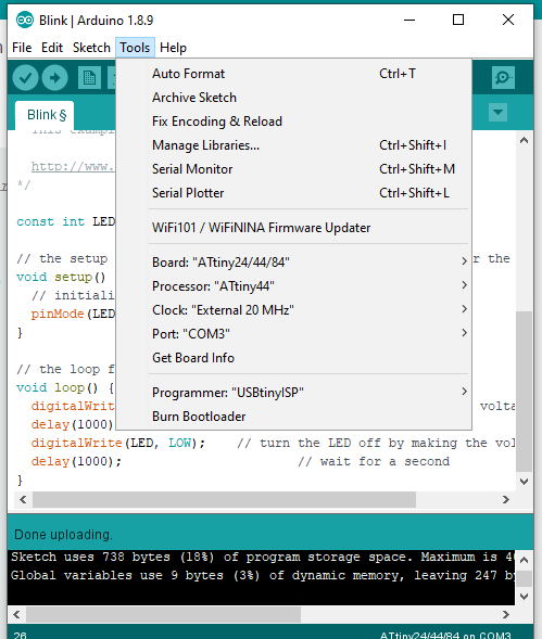
When this was done, I then tried running the basic Blink program on the board. This did not work, I learnt that this was because I had not set the right pins. Since, Arduino and the AtTiny have different pins for different purposes - it is important to declare the right pin for each task. Luckily, there is a sheet that shows what pin is the right/equivalent one.
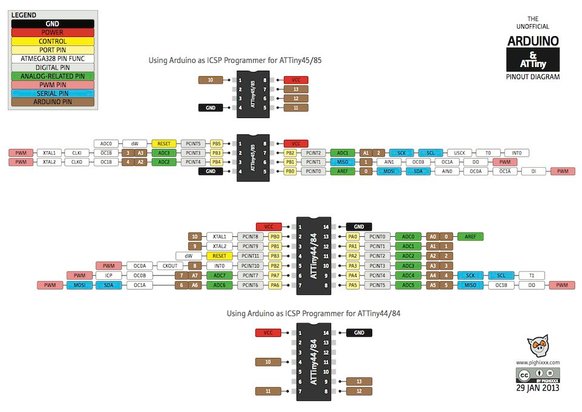
Once, I changed the pins in the code to the equivalent ones I was able to execute the blink code. The next thing was to program the button so that the blinking of the LED would be controlled by the level of the button. I had some tiny issues here and my instructor, Francois, explained to me that buttons can reverse the way circuits flow because of the pull-up resistor. The overview of the working code is below:
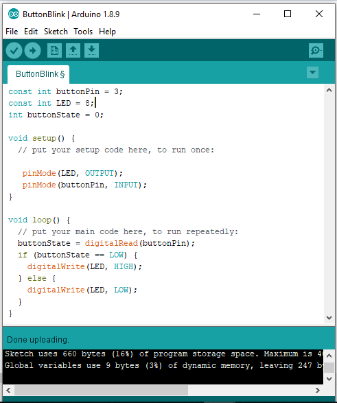
And a view of it working in shown in the video below, the code for the program is available here.