
Assignment Seven: Electronics design and simulation
This week's task is to design circuits, create boards for the circuit using KiCAD or Eagle, and then test the connections. An additional credit will be to simulate the circuit - during the class I got interested in Falstad, and will try to use it. The assignment in steps:Group: use the test equipment in your lab
Design a circuit
Simulate the circuit using Falstad
Create an electronic board and test it
Group: use the test equipment in your lab
This week, the group project is led by Francis and is hosted on his webpage. The task is to use the test equipment in the lab to observe the operation of a microcontroller circuit board.Design a circuit
Our task for this week is to add a little changes to the Hello Board. For me, I wanted to learn about the circuit and what the different components do that make the board work correctly. I learnt about the FTDI used in the Hello Board so as to get output results from a serial port, and on Stack Exchange I learnt about the different between resonators, crystals and oscillators. Those were quite interesting for me.
Being from a mechanical background, I have mostly hated electronics. But I think I just need to be more open minded and be patient to learn more.
I decided to use EAGLE, only because I think that as a paid product it would be easier to learn. Thankfully, there were beginner resources on their website. Using this, I created a new project and opened a new schematic page.
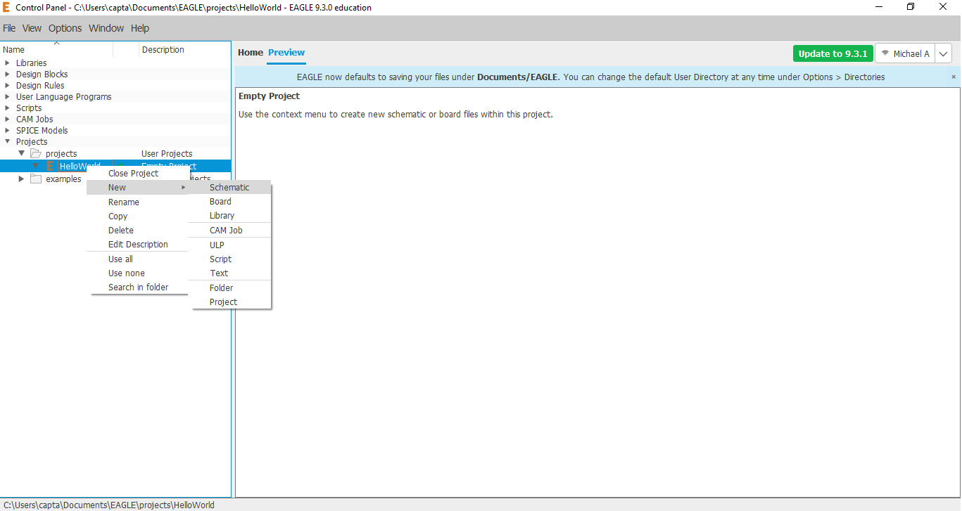
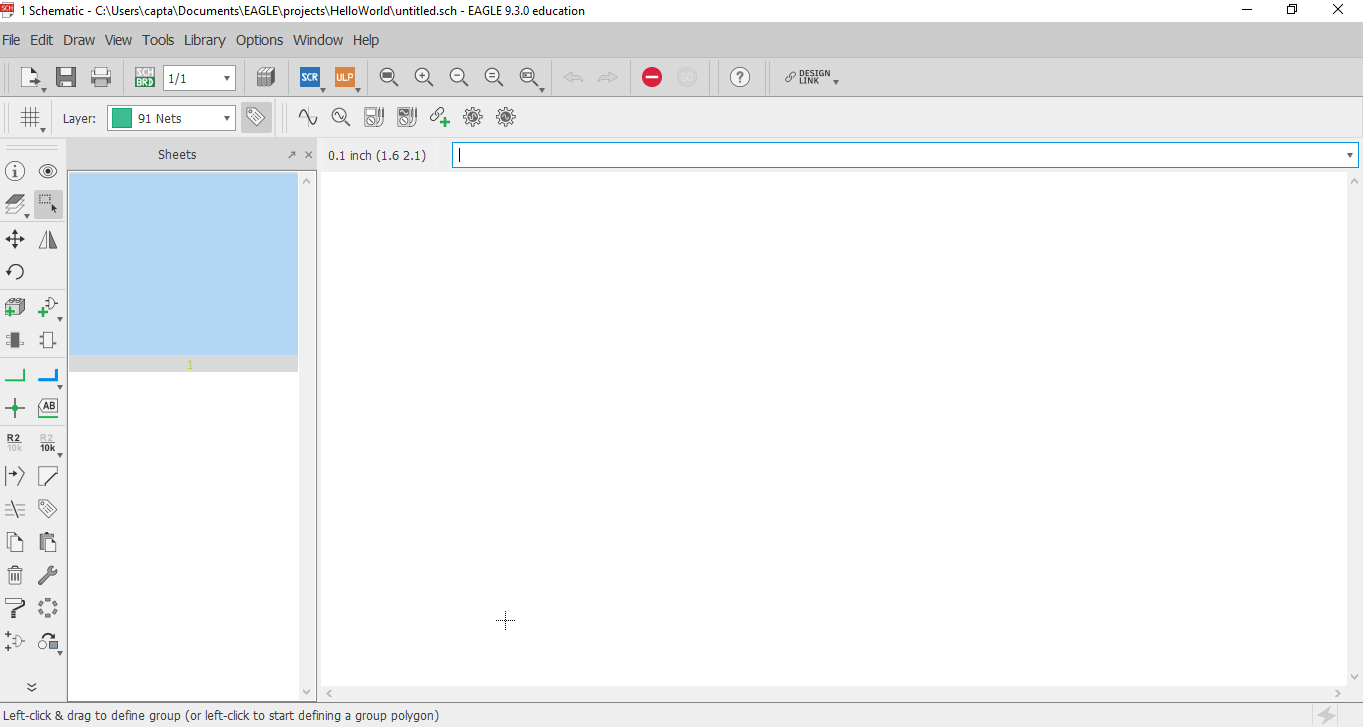
After this, I added the FabLab Eagle Library to my Eagle directory and changed the setting to Use. With this, I started to import the components one after the other into the schematic surface.
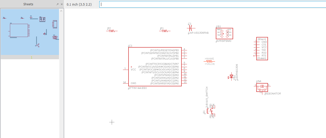
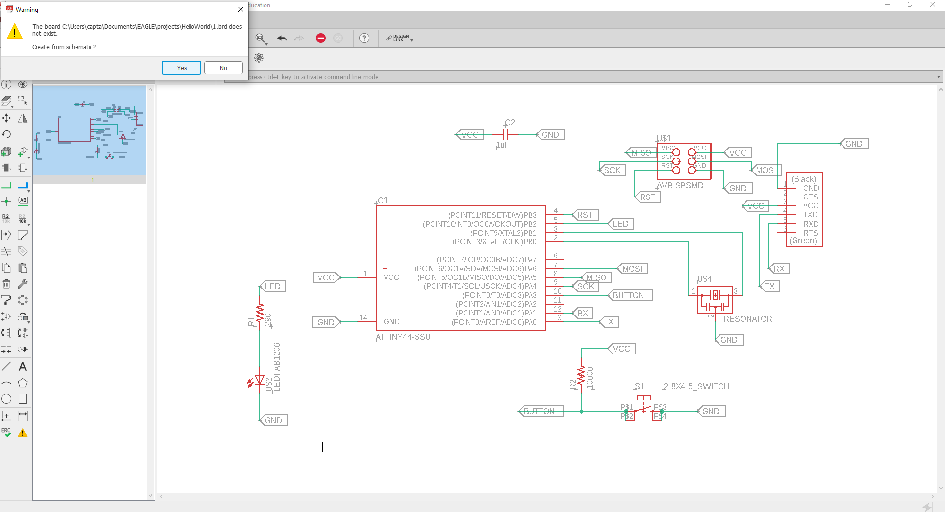
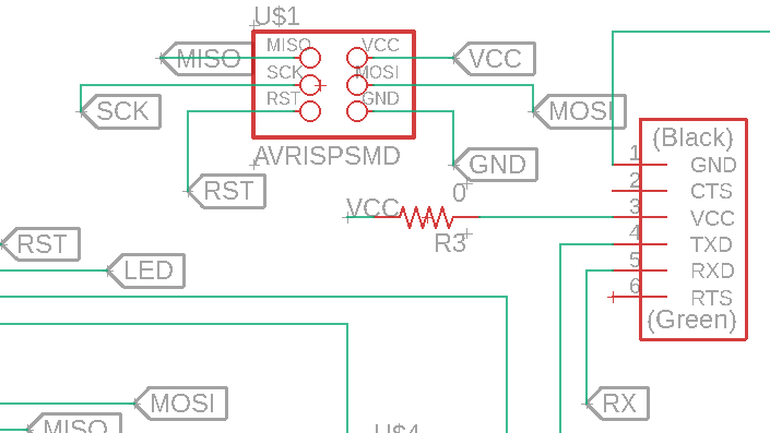
The parts there are: FTDI, ISP, Attiny-44, Resonator, two resistors (10K and another), a 1uF capacitor, a switch, and an LED. In order to connect them, I changed the Pin Breakout setting as suggested in the tutorial to use Pin names - this made it easier to connect. Once I was done adding the components, I then started connecting them together in the schematic page. Eagle is pretty nice as you can connect two points by using similar names - this was explained to me in the tutorial.
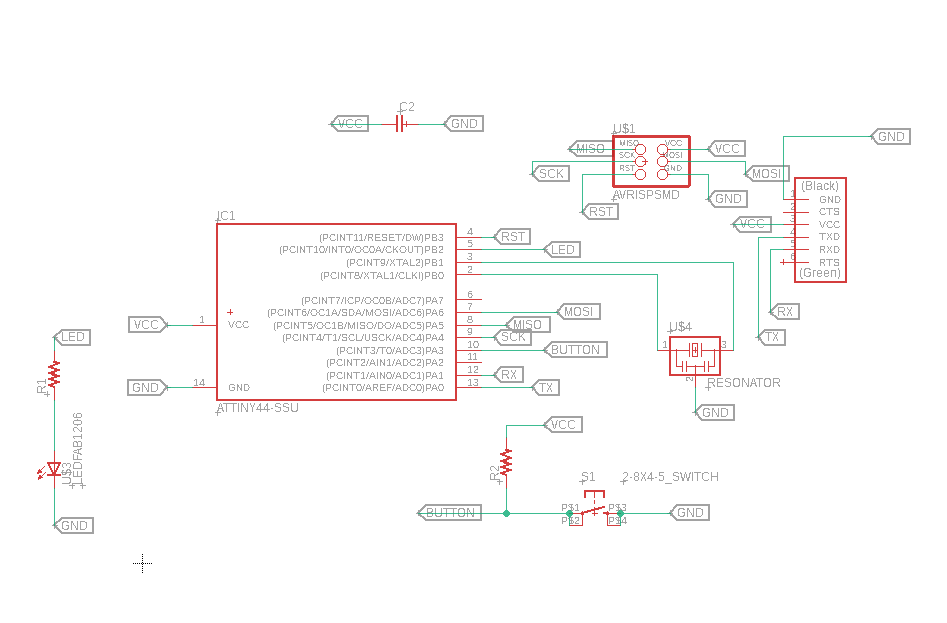
Another interesting thing is that we needed to include a pull-up resistor for the switch. This tutorial has a good explanation for this. My understanding of this is that a pull-up resistor helps to reduce the current that passes through the input pin and also prevent shorts in the circuit if it was connected directly to ground.
After connecting all the pins, it looked like this:
After this point, I had started watching Jeremy Blum's tutorial videos on Youtube. To assign the value of the resistance for the parts, I checked the part's datasheet on Digikey and was able to determine that for a supply voltage of 2.1V from 5V from the VCC to send 10mA of current as wanted by the LED, the resistor should be 290 ohms. I also set a 10K resistor for the pull-up. Once, I was done with this, I clicked the generate button to make the board layout.
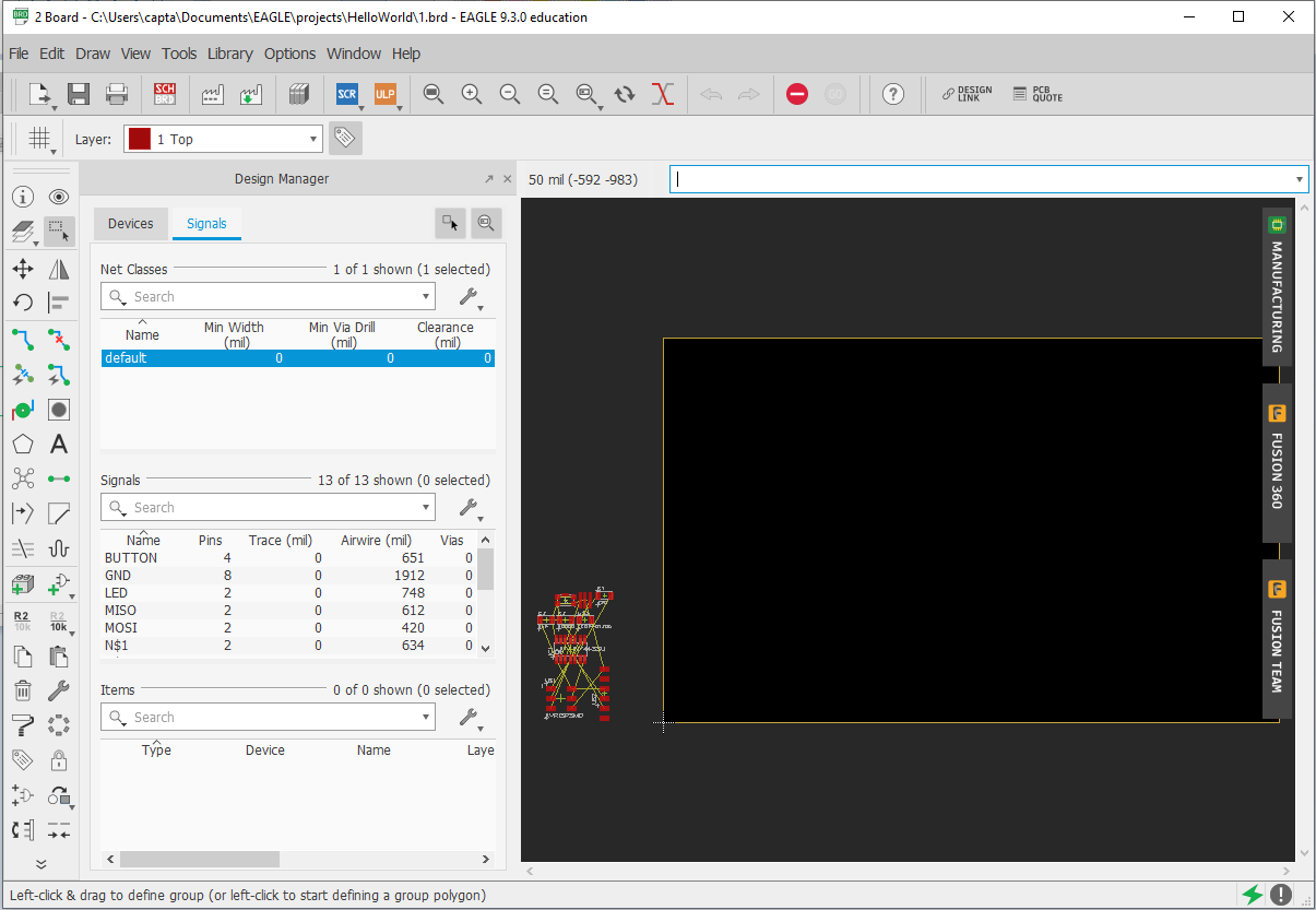
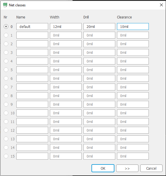
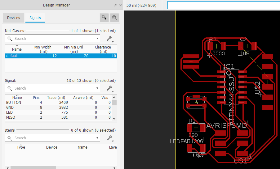
After moving everything to the board, I used the autorouter tool to connect all the parts. Before that though, I changed the default net classes to 12 mill for width, 20 mill for drill and 10 mill for clearance.
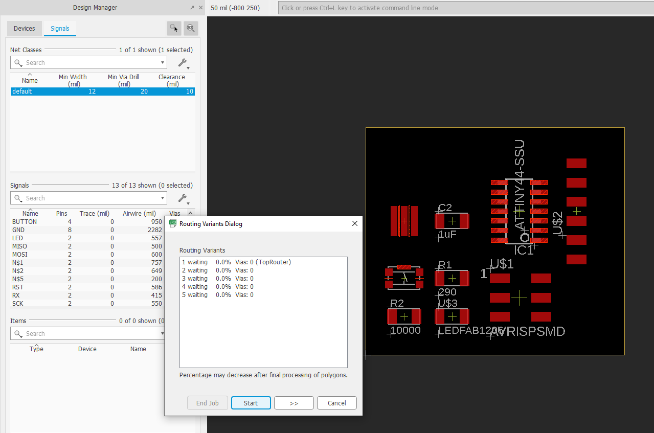
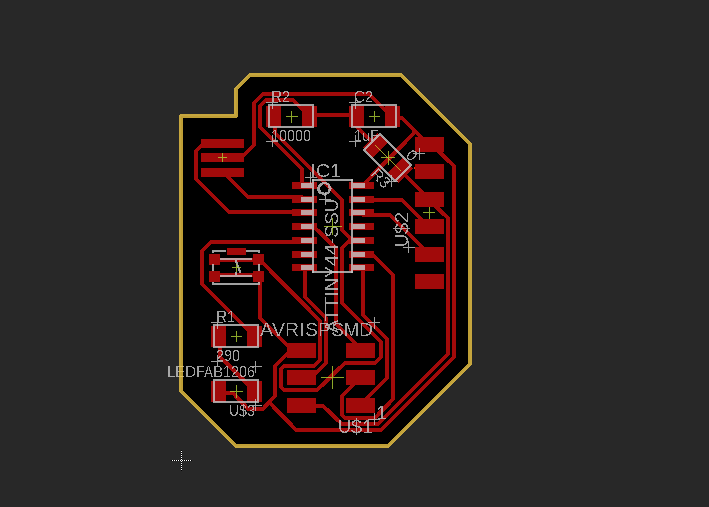
After a first wrong try, I got a 95.8% completetion with the autorouter, which connected the design below.
I discovered here, with the help of my instructor, that the issue was with the connection from the FTDI to the VCC line. Francois advised that the best solution was to add a 0 ohms resister to serve as a bridge. To do this, I added a 0 ohms resister to the schematic which generated immediately in the board diagram. Then I connected it across in the board layout, made the dimension outline and voila!
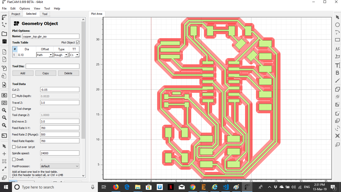
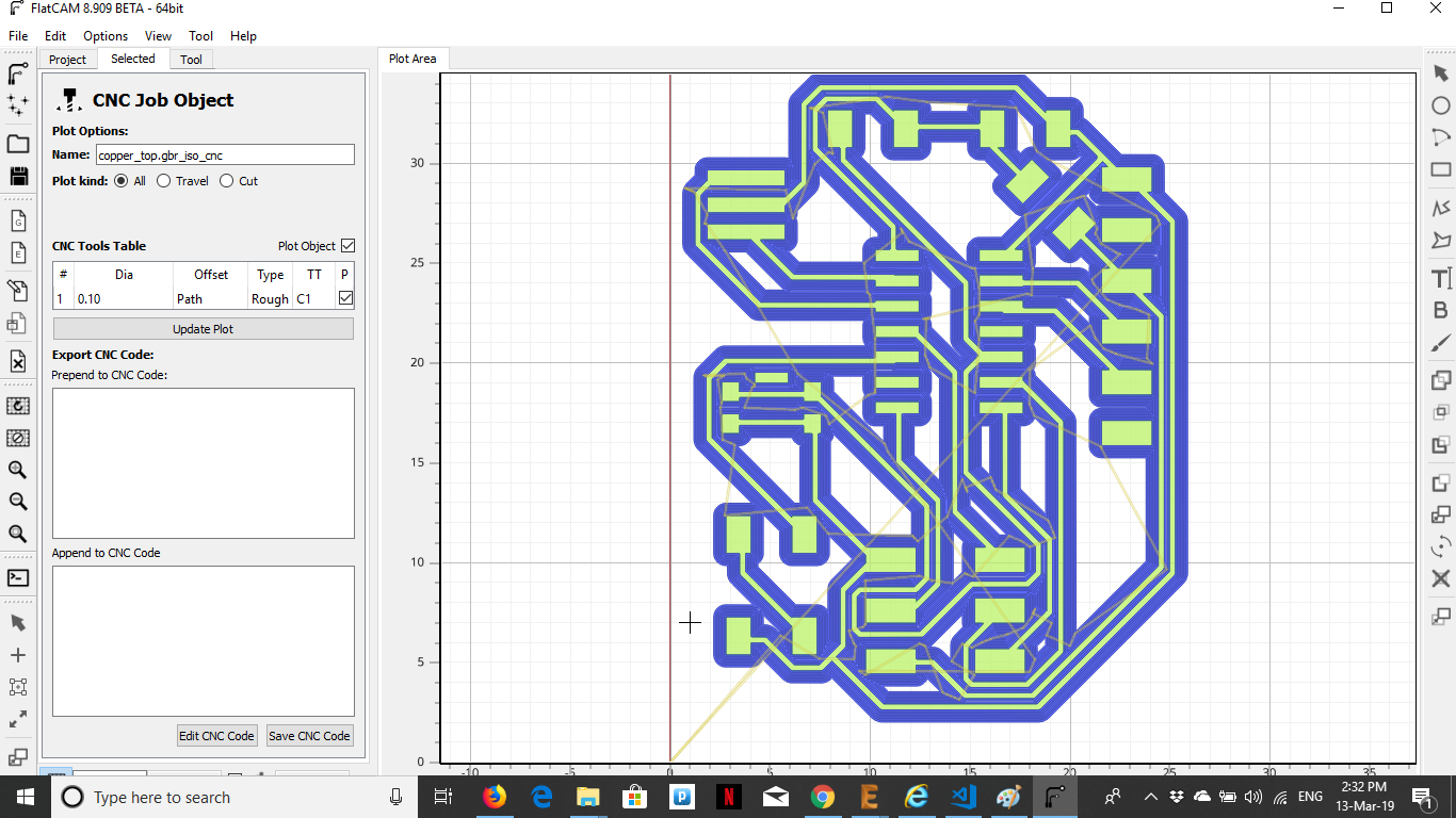
After this, I used the CAM Processor to generate the Gerber Files and loaded these files into FlatCAM to generate the GCode for the CNC Mill.
Simulate the circuit using Falstad
[more to come]Create an electronic board and test it
The GCode from FlatCAM is saved here. After making the board, I soldered on the parts.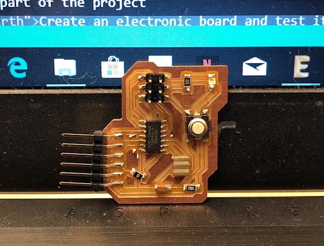
Reflection: It turned out that I had used the wrong switch in the Fab Library so I had to change it in my schematic and redo the board design. This was easy enough as I had just gone through the whole process. This thought me to be more careful when choosing parts in the library as I have to make sure that the parts I pick are actually available.