
Assignment Five: Make a circuit board with the CNC and program it
This week's task is to develop the skills to make circuit board cuts with the CNC machine, solder parts to the PCB and program the board. In steps:Generate the G-Code for the board from a picture or file
Cut the board on the CNC and solder the parts
Run a program on the circuit board
Generate the G-Code for the board from a picture or file
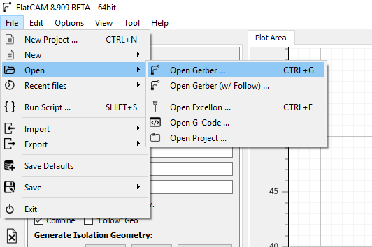
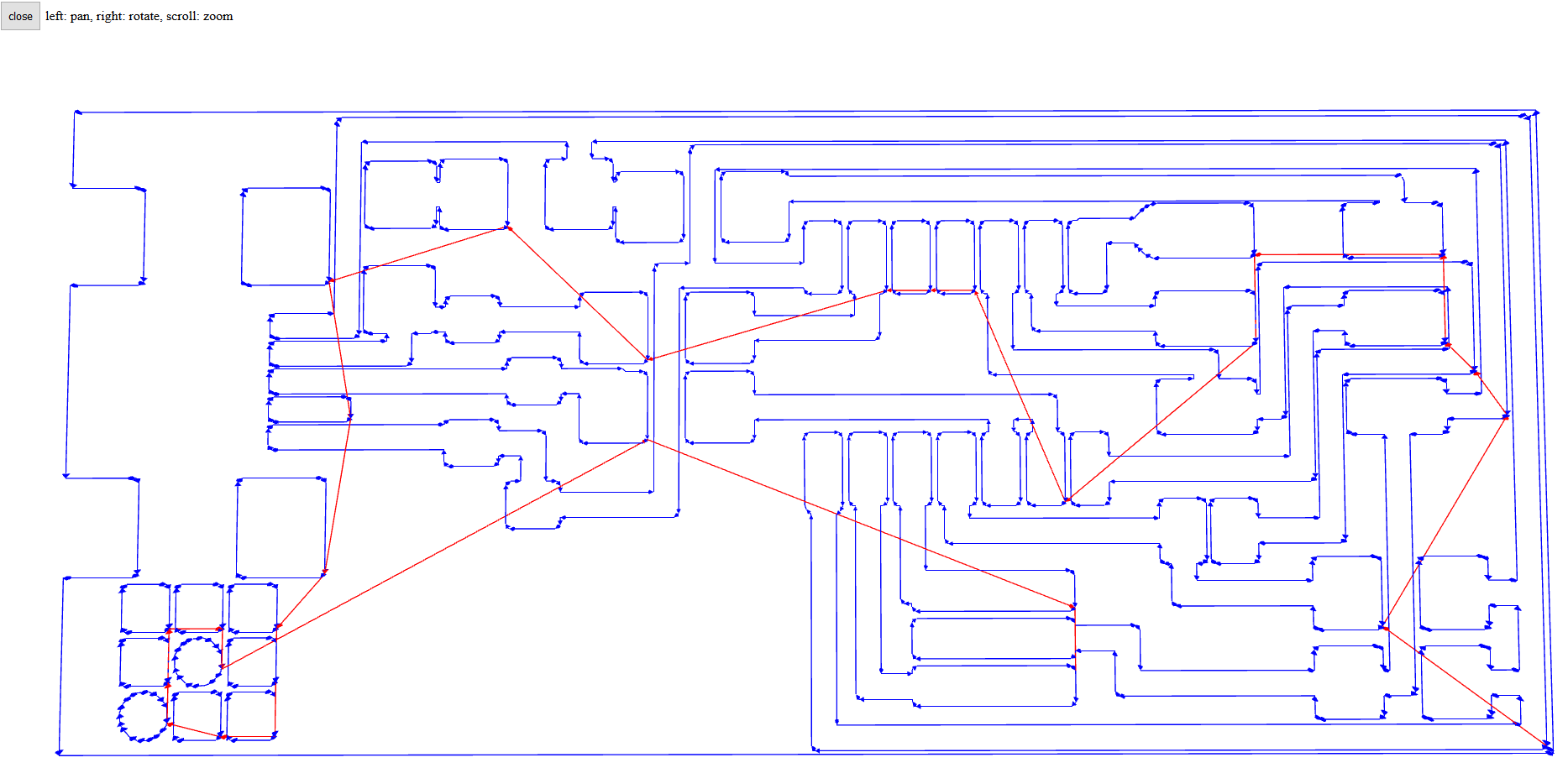
The first step for this project was to get the design for the board from the instructor Francois, as we haven't learnt to use Eagle yet I can't design the board yet. Once I got the Gerber files, I installed FlatCAM - which is a great software to generate G-Code for a CNC.On installing the software completely, I could open the Gerber files and learn to use the software using the manual. Using the command Open Gerber, I opened the gerber_top file and it showed on the interface.

As it's the first time using the tool, it's important to use the first the default units as mm instead of inch - this can be done by changing the preferences and saving the settings. Next, I set the tool parameters, like 7mm for the width and number of passes, as well as the diameter of the bits. Once this was done, I used the FULL GEO command to generate the trace geometry for milling the 2D shape.
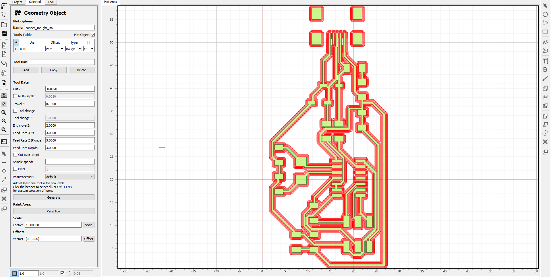
Once the trace was generated, I then included the trace for the cutout of the board and saved the G-Code. The file is available here.
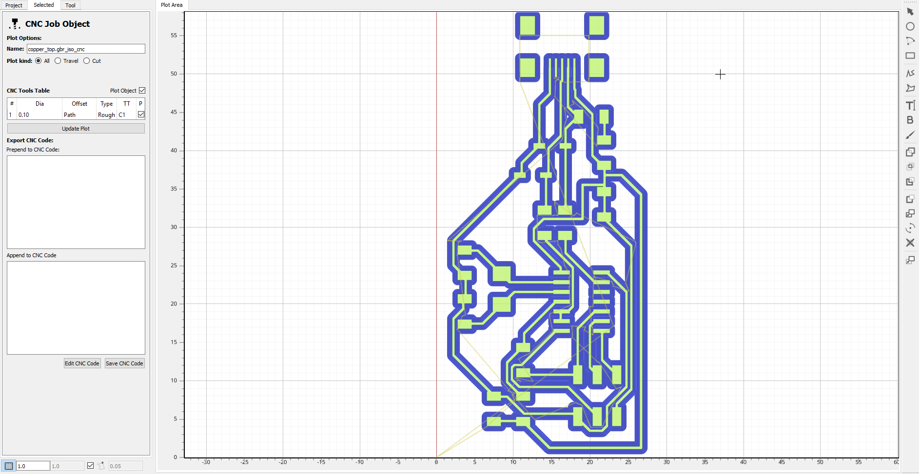
There are other ways to generate G-Code from a picture such as mods, another method would be to use Fusion 360 to convert an SVG or even use a software like MakerCam. I tried it out with mods using a PNG template from the Fab Academy class and got the toolpath below (GCode here), which is pretty useful. I can see how mods can be used for even more intricate designs, I look forward to trying it out in the future.
Cut the board on the CNC and solder the parts
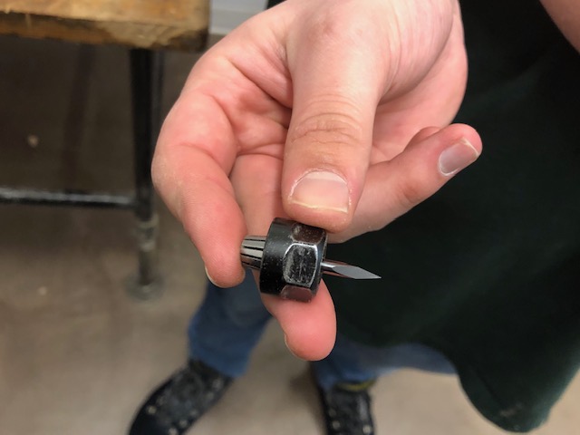
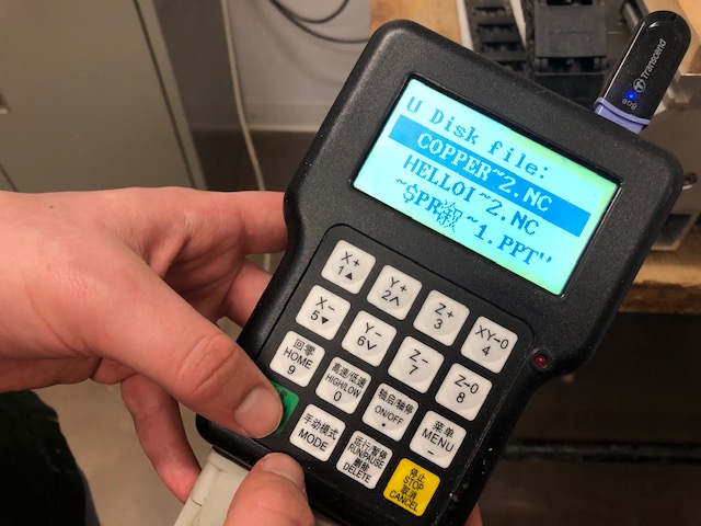
Once I had gotten the G-Code, I saved it on a USB and got it to the CNC in the lab. The lab uses an SMX CNC router which is capable of a lot of jobs. The first thing to do was change the drill as well as the settings used on the board. I also had to learn how to use the control pad to hover on the x, y and z axes. This was great as it's my first time using a CNC Mill.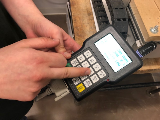
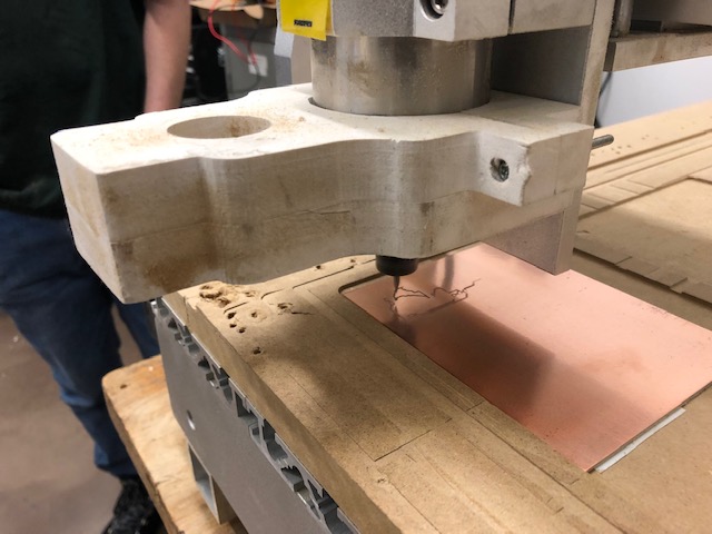
Next, I set the double-sided tape under the board and fixed it to the router bed.
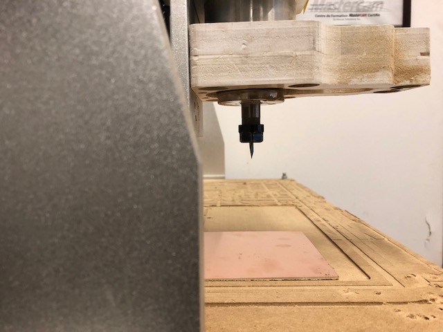
Francois, my instructor, taught me a very interesting skill to know if the drill is right on top of the board - by using the multimeter to detect contact between the board and the drill! This done, we selected the G-Code file as well as the speed for cutting.
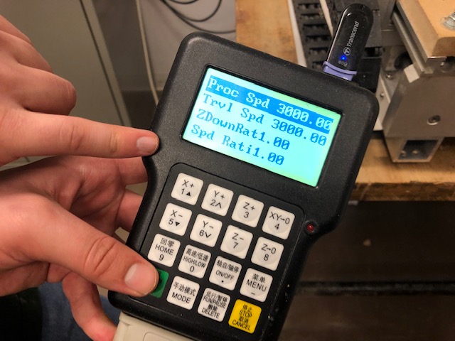
Next, we ran the Mill and in a few minutes had the board ready!
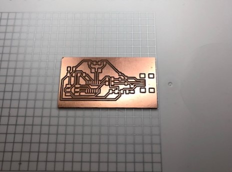
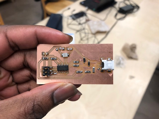
The next step was to solder the board using the reference drawings shown here. I first arranged the parts list in order and proceeded to solder the board. My colleagues at the lab gave me some helpful tips here so I soldered the USB pin first then went ahead to try do the other parts one after the other. At the end I had the board ready as shown below!
Run a program on the circuit board
After assembly, the next step is to make the board a programmer like an ISP. ISP are short for In-system programming (ISP), which is the ability of some programmable logic devices, microcontrollers, and other embedded devices to be programmed while installed in a complete system, rather than requiring the chip to be programmed prior to installing it into the system.Our lab initially had some issues with this part of the assignment, but one of us - Phillippe - discovered that this was due to our Zener Diode generating a lot more capacitance and stopping the circuit from working normally. You can take a look at this excellent analysis here. Once, we established that this was the issue we replaced the zener diode and our circuit worked like magic!
For this process, the first thing - before you even install the software - is to debug the board by checking all the components with a multimeter to make sure all the parts are connected properly and there is no short circuit anywhere on the board. I had some issues soldering my USB pin and had some short circuits, but then I broke the solder and had to redo some parts.
For a Windows user like myself, I followed Brian's installation instructions. Most people in my lab have Mac or Linux systems which are much easier to use, it would seem.
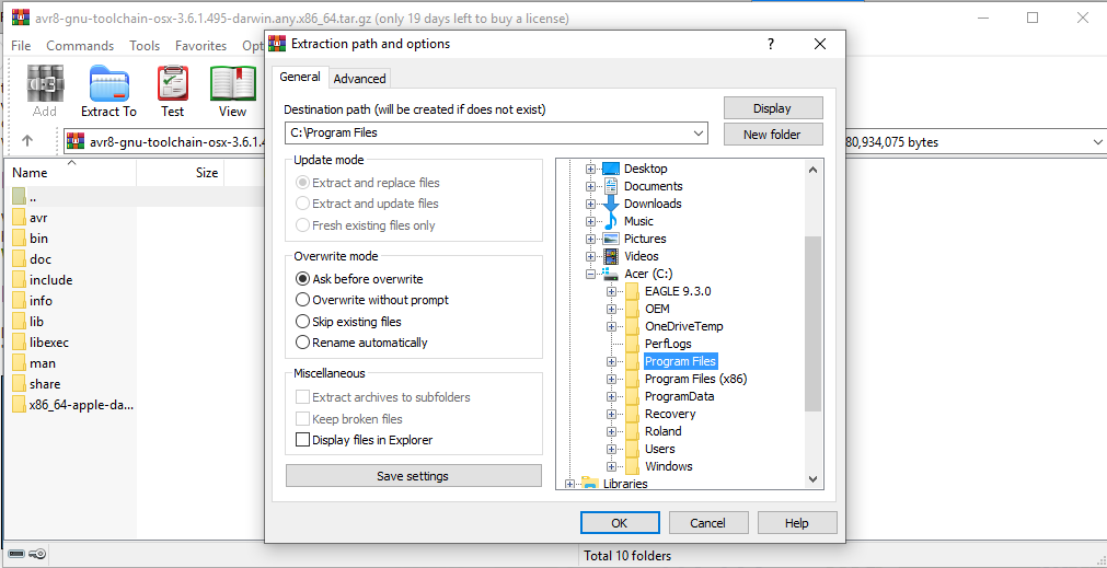
I downloaded the AVR Toolchain for Windows and went on to extract it to my Program Files directory.
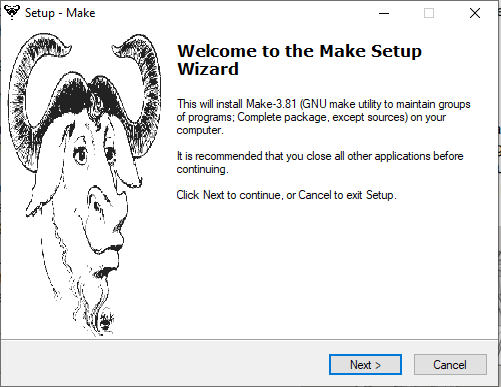
Then, I downloaded GNU Make from the CBA website and installed it in the default folder, as Brian's tutorial had instructed. I even added it to the Start Menu.
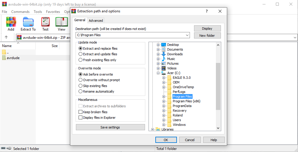
Next, I downloaded avrdude and extracted it to C:\Program Files.
Then, I went ahead to change the PATH settings in the Control Panel. I learnt that this is to change what the controls mean when you write them.
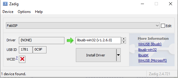
Because we are using a FabTinyISP to install the new one, it can be quite tricky. To make it easier, I used Zadig which is a USB Driver installer for Windows. Then, I plugged in the 'FabISP' which I am using as my programmer and selected the libusb-win32 as the driver to install to it. I then let it install.
To check if all was working well, I opened up Git Bash and checked for Make, the GNU toolchain as well as avrdude.
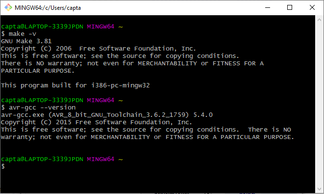
They worked!
Now, it's time to program my board. Using the firmware file provided for my Attiny44 controller, I started the process by opening Git Bash in the folder I extracted the firmware to and then running make fuse.
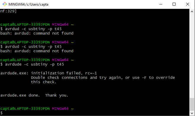
Even though the fusing worked on my computer, and trying to execute make program worked correctly, my computer failed to recognize the board as FsbISP. I could not figure out why this was wrong as all the programs were correct for the Attiny. When I tried to do the same on my instructor - Francois' - Linux computer, it worked perfectly and generated the hex file.
Reflection: Many things can go wrong even though this is a very easy process, it is important to troubleshoot as much as possible especially with the different make instructions: make clean, make fuse etc.
I will keep trying out the make instructions on my computer to see where I could be making the errors.