
Input devices --- Մուտքային սարքեր
Introduction --- Ներածություն
For this week we had to:
measure something: add a sensor to a microcontroller board
that you have designed and read it (individual assignment)
probe an input device's analog levels and digital signals (group assignment)
Since the guitar PCB that I've designed didn't work (I spent a
week trying to fix it) I decided to use
Neil's echo.ftdi.45 PCBs and concentrate more on learning how to use different sensors.
I've made PCBs and tested with:
Switch (button)
Hall sensor (magnetic)
Temperature sensor (thermistor
NTC).
Making of the PCBs --- Տպատախտակի պատրաստում
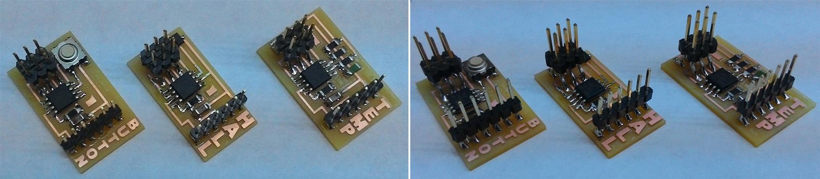
The most interesting thing I did here was that I've added names of the sensors on the PCBs and used different Work Coordinate Systems not to change the endmills back and forth while milling them.
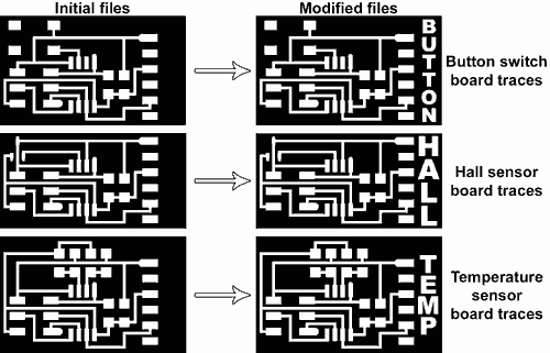
As you can see from the left picture of the PCBs, all of them have a quite big unused space near
the FTDI pins. So I thought adding names would make sence.
Since the traces were in .png raster
graphics I used Adobe Photoshop
to modify them although you can use any other raster software like Gimp or Krita.
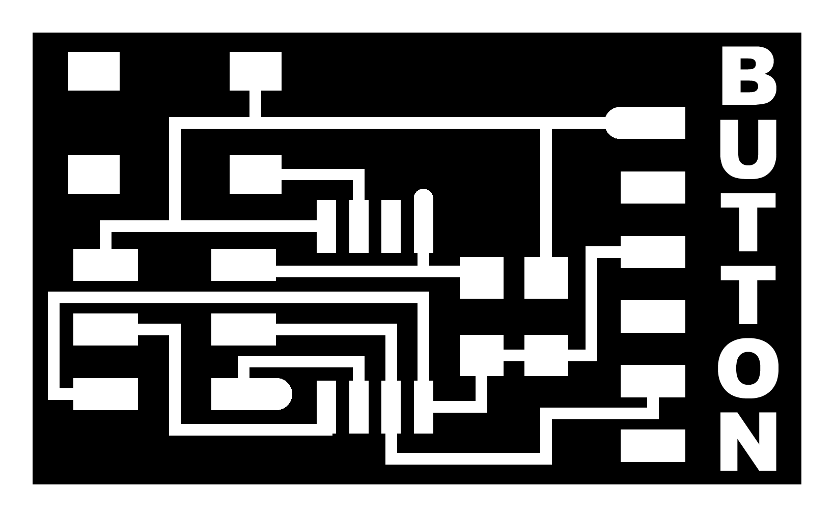
Here are the echo.ftdi.45 boards with the names added:
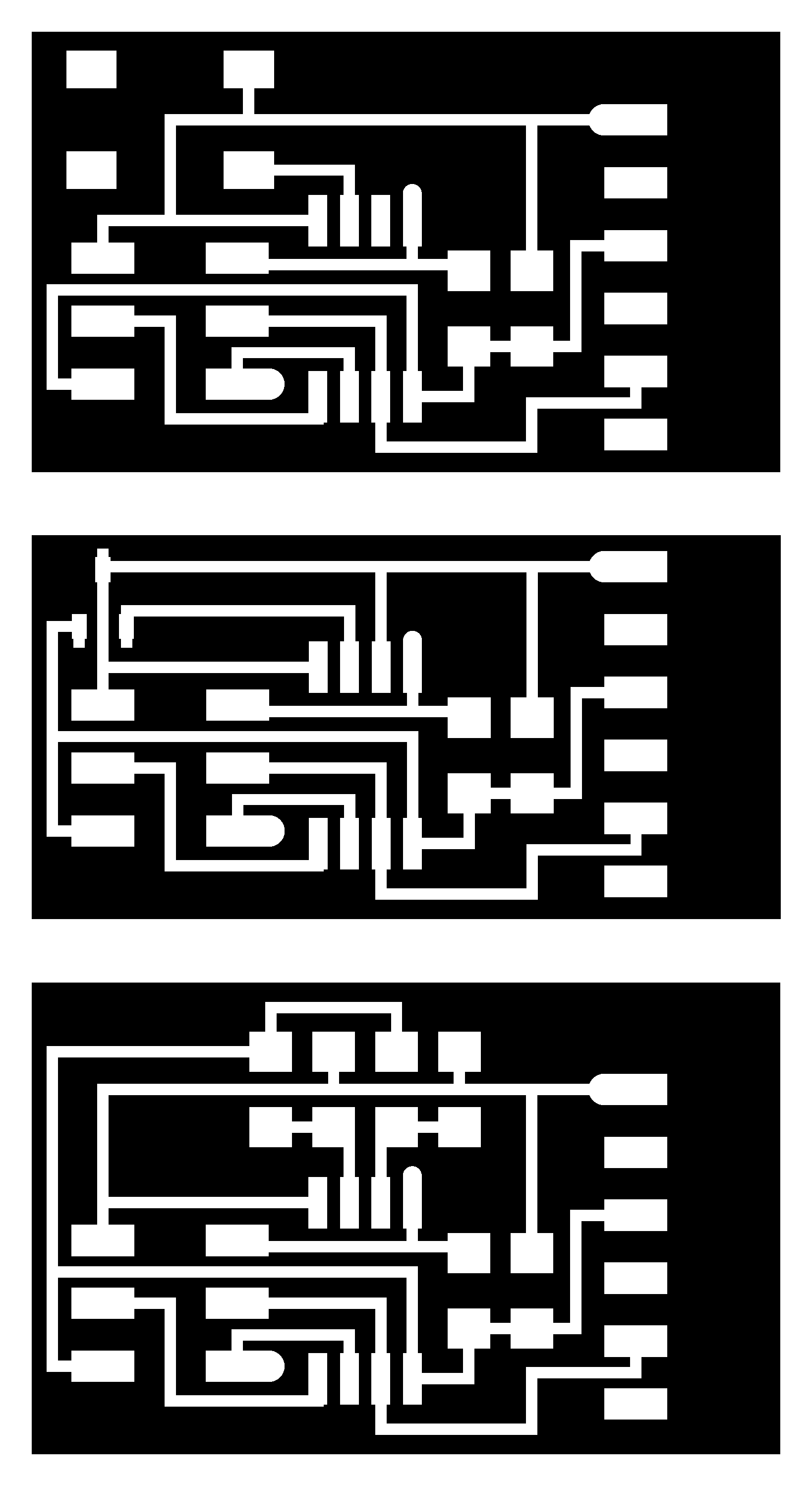
hello.button.45 traces,
and it's interior
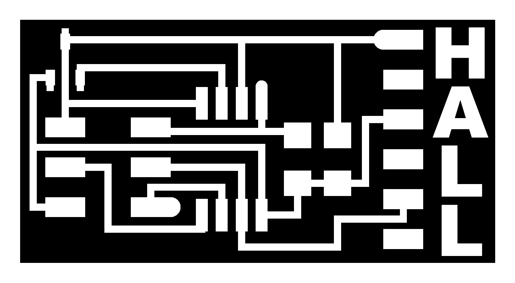
hello.mag.45 traces, and
it's interior
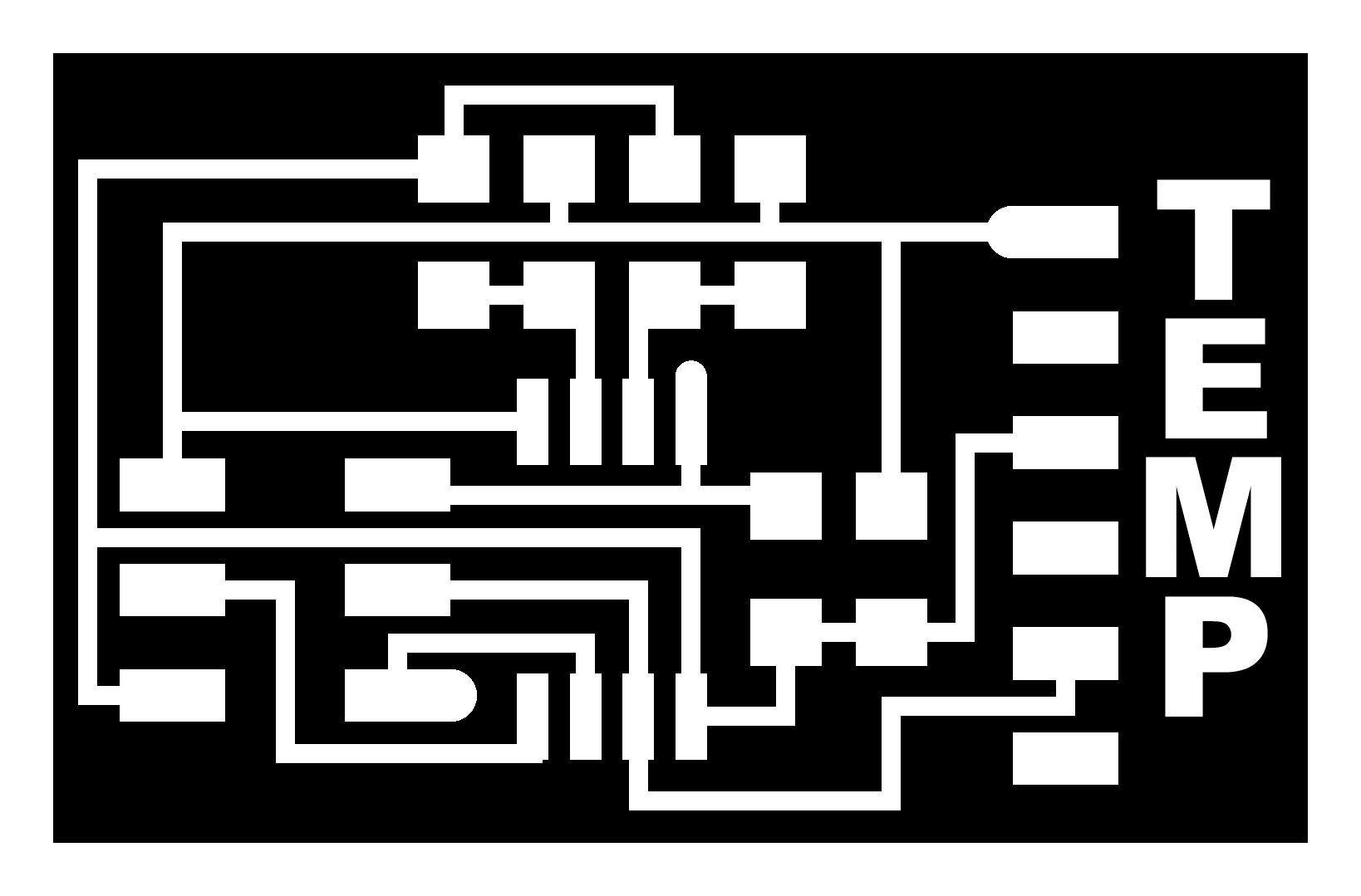
hello.temp.45 traces, and
it's interior
I used the "Vertical type tool" from the tools menu in the left hand side of the interface
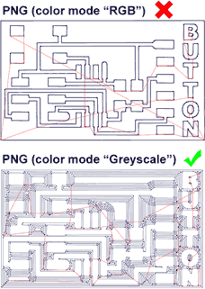
and typed the names. I saved it in .png and the fabmodules couldn't generate correct toolpaths
(right picture).
It tourned out that the png color mode needs to be in "Greyscale" in order to have correct
toolpaths. I changed the color mode to "Greyscale" and it worked.
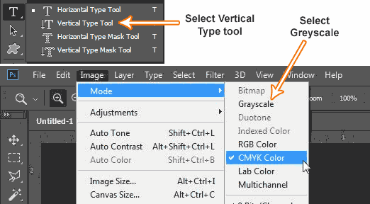 To change the color mode you need to go Image>>Mode>>Greyscale third tab from the
upper side of the interface. In some programs it may be called also "monochrome" mode.
To change the color mode you need to go Image>>Mode>>Greyscale third tab from the
upper side of the interface. In some programs it may be called also "monochrome" mode.
The I generated the G-codes for eache board's traces and cutout. I had to mill 3 boards
consequently I had to change the endmill from 1/64 for traces and 1/32 for cutouts 6 times. One
way to do that is to combine all 3 boards into one file.
Here are the echo.ftdi.45 boards in one file:
hello.button.45 traces
COMBINED, and it's cutouts COMBINED
The other way to do it is by using different Work Coordinate
Systems. Fabmodules generates G-codes with G54 as a default work coordinate system, so
when you load
you have to set only G54's XY and Z. but we hae 5 more coordinate systems that we can use
G55-G59. I decided to use G54 for Button board, G55 for Hall sensor board and G56 for
Temperature sensor board.
In order to change G-codes work coordinate system you can simply edit it by any text editor in
my case I did that with Notpad find the G54 (should be in the 5th row), rename it from G54-G59
and save it.
I milled the first board with G54 then zeroed G55 next to the first board and milled the next
one with G55 then zeroed G56 next to the board I milled with G55 and milled the next board with
G56. Then I changed the tool to 1/32 inch
flathead endmill and made the cutouts by zeroing only the Z for each work coordinate system.
Soldering the components --- Բաղադրամասերի զոդում
You can find the component list in Neil's keynotes for Input Devices but I will post them here too.
For Button board you need
1xATtiny
45
1x10k SMD 1206 Resistor
1x1uF SMD 1206 Capacitor
1xB3SN-3112P
Push button
1x 1x6 male pin headers
1x 2x3 male pin headers
For Hall sensor board you need
1xATtiny
45
1x10k SMD 1206 Resistor
1x1uF SMD 1206 Capacitor
1x Sensor
Hall Effect
1x 1x6 male pin headers
1x 2x3 male pin headers
For temperature sensor board you need
1xATtiny
45
4x10k SMD 1206 Resistor
1x1uF SMD 1206 Capacitor
1x Thermistor
NTC 10K
1x 1x6 male pin headers
1x 2x3 male pin headers
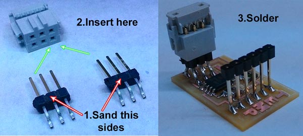 The only pinheaders that could reach the footprints for ISP were this but the problem was they couldn't
fit into the female socket so I decided to sand the plastic holders from one side to fit them.
The only pinheaders that could reach the footprints for ISP were this but the problem was they couldn't
fit into the female socket so I decided to sand the plastic holders from one side to fit them.
Another interesting solution I came with was to insert the pinheaders to the female socket and
solder that way. It ensures that the pinheaders will stay straight and aligned during soldering and that
the cocket will fit perfectly.
Here are the final boards
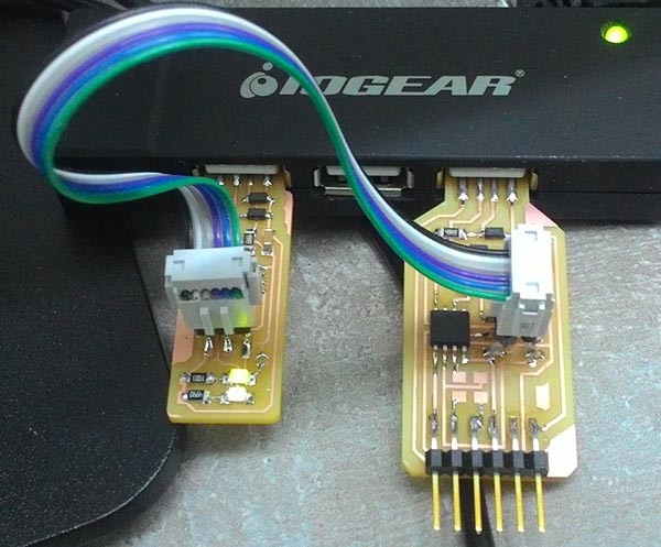
Making of FabFTDI -- Ինքնաշեն FTDI սարքի պատրաստումը
I decided to make the FabFTDI and explore it a little. There are two FabFTDI boards that you can make here
are the links:
Atmega16 FabFTDI This is USB 2.0 Full-speed
device and supports upto 38400bps of serial communication.
ATtiny45 FabFTDI
This is a low-speed USB device and supports from 1200 - 4800bps.
I choose the second one. One problem I came across was that it uses two 470om resistors that I couldn't
find at fablab. I bought them later in Yerevan from a hardware store that everybody calles
"radiolover". The price was 10 drams for one smd resistor that's 2 US cents.
 Programming of FabFTDI
Programming --- Ծրագրավորում
At this point my frustration begun. Now I understand why good documentation matters. The only thing I found that somehow made sense for me was Ciro Mejia's Input Devices 2014 assignment. I used Ubuntu and usbtiny we made on week5 to program the boards. In order to program this boards we will need the C codes, makefiles and python programs to read data from the keynotes for each board my advice is to keep them in separate folders and name them "Button" "Magnet" "Temperature" Here are the files zipped and grouped:C files, Makefiles and python programs just unzipp this somewhere and you'll have the files in folders.
Button board
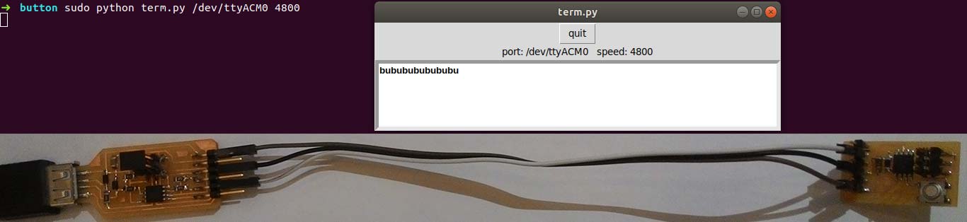
Connect your usbtiny (FabISP) to the button board's ISP port a and your computer's USB port, connect FTDI
cable to the USB of your computer and to the FTDI 6pin on the button board
Open the "Button" folder right click and select "Open in Terminal"
Type this command and hit enter:
make -f hello.button.45.make program-usbtiny "program-usbtiny" specifies the programmer we're
going to use change "usbtiny" to "avrisp2" or "dragon_isp" if you're using those programmers
Then type this command and hit enter
avrdude -p t45 -P usb -c usbtiny -U flash:w:hello.button.45.c.hex
Then install python's serial module in order to be able to read data through FTDI cable
sudo apt install python-serial
Make sure your FTDI cable is seen, type:
ls /dev and find "ttyUSB0"
Finally type:
sudo python term.py /dev/ttyUSB0
In my case I used FabFTDI and in this case you need to change /ttyUSB0 to /ttyACM0 and baudrate to 4800
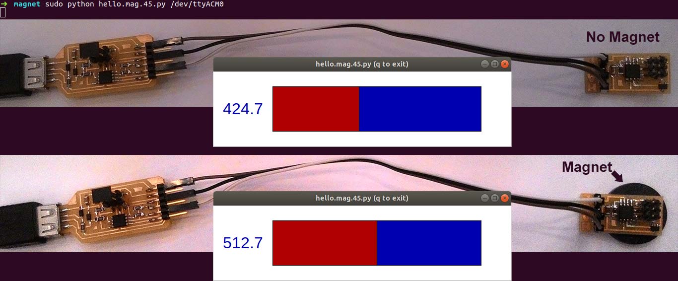
Hall sensor board
Connect your usbtiny (FabISP) to the Hall sensor board's ISP port and your computer's USB port, connect FTDI
cable to the USB of your computer and to the FTDI 6pin on the Hall sensor board
Open the "Magnet" folder right click and select "Open in Terminal"
Type this command and hit enter:
make -f hello.mag.45.make program-usbtiny "program-usbtiny" specifies the programmer we're
going to use change "usbtiny" to "avrisp2" or "dragon_isp" if you're using those programmers
Then type this command and hit enter
avrdude -p t45 -P usb -c usbtiny -U flash:w:hello.mag.45.c.hex
Finally type:
sudo python hello.mag.45.py /dev/ttyUSB0
In my case I used FabFTDI and in this case you need to change
/ttyUSB0 to /ttyACM0
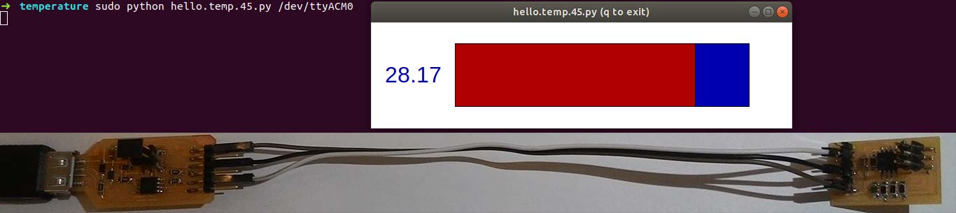
Temperature sensor board
Connect your usbtiny (FabISP) to the temperature sensor board's ISP port and your computer's USB port,
connect FTDI cable to the USB of your computer and to the FTDI 6pin on the temperature sensor board
Open the "Temperature" folder right click and select "Open in Terminal"
Type this command and hit enter:
make -f hello.temp.45.make program-usbtiny "program-usbtiny" specifies the programmer we're
going to use change "usbtiny" to "avrisp2" or "dragon_isp" if you're using those programmers
Then type this command and hit enter
avrdude -p t45 -P usb -c usbtiny -U flash:w:hello.temp.45.c.hex
Finally type:
sudo python hello.temp.45.py /dev/ttyUSB0 9600 // this is for FTDI cable
In my case I used FabFTDI and in this case you need to change /ttyUSB0 to /ttyACM0
 Useful links
Jasmin Rubinovitz week11
KATI PITKÄNEN week12
INTRODUCTION TO FTDI BITBANG MODE