
Electronics Production
Introduction
Next year is the 100th anniversary of William Shockley (1910
–1989) the inventor
of the Transistor (
a milestone of the third millennium), and the father of Silicon Valley and finally
it's the 580th anniversary of Johannes Gutenberg who
introduced mechanical
movable type to the world a milestone of the second millennium. In the framework of
global
paradigm shifts this week is exeptional. We will learn different tecniques of making Printed circuit board (PCB),
mounting electronic components and finally
programming them. The evolution of mounting schemes used for electronic components is very
interesting:
1.Point-to-point
construction (tag boards or turret
boards)
2.Through-hole technology
(THT)
3.Surface-mount technology
(SMT)
I liked Honghao
Deng's
example, he made a version
of FabTinyISP
AVR ISP programmer/board
using vinyl cutter and copper foil tape. He gives a tip that transferring copper foil
from it's original backfilm to transfer tape's backfilm dramaticaly increases the quality of the
cuts. So I wanted to try this.
FabTinyISP
FabtinyISP is a 100% fabable ISP (In System Programmer) based on the FabTinyStar board, which was specificly designed to be made in a FabLab. FabTinyISP enables microcontrollers to be programmed while installed in a complete system, rather than requiring the chip to be programmed prior to installing it into the system. In other words it allows us to program microcontrollers on other boards we make.I recommend to read this paper Demystifying
the FabISP before making the ISP In System Programmer, where you can learn in detail the
purpose of each
component on the board. Here are some points that I belive are essential:
1.Pull-Up & Pull-Down
Resistors
2.Decoupling
Capacitors
3.Diodes
Making of PCB
We will mill the Printed circuit board and solder the componets. The milling machine that we'll use is Roland-monoFab SRM-20 you can find it's manual here. We teamed up with Miqael to explore our machine and to mill the recommended linetest pattern and it's cutout. We used 1/64in(0.4mm) endmill for milling the PCB traces and 1/32in endmill to cut out the PCB from the base material in our case FR-1.
Setting up the Machine
It's always a good idea to follow the manual.
1.Make sure the machine is clean of cutting waste.
2.Turn the Power On
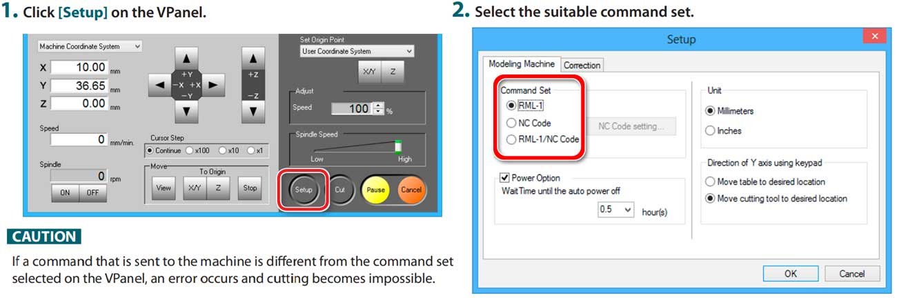
3.Open the VPanel (This is a dedicated software
for controlling the machine)
4.Confirm the Command Set (in our case we'll be using NC code-Numerical control) This is the
"language" that we'll be using to communicate with the machine and send the cutting commands.
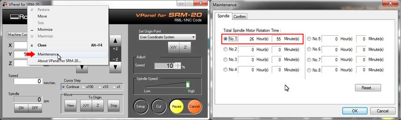
5.Check the total Spindle motor rotation time (image below). It is recommended to change spindle motor after 500hours in our case it was about 27hours so we are ok to go.
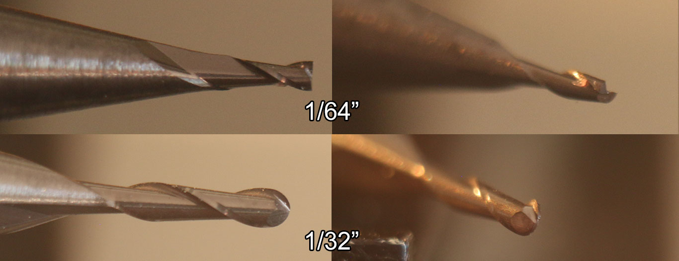
6.Attach the cutting tool (image below). It's a good idea to mill the surface of the material and make the cutout from the base material after. In our case we will use 1/64in(0.4mm) endmill for milling the PCB traces and 1/32in endmill to cut out the PCB from the base material in our case FR-1. I made some macro photos of the endmills. They are magnified 200 times.
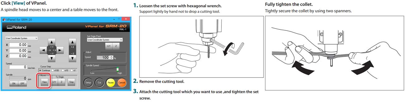
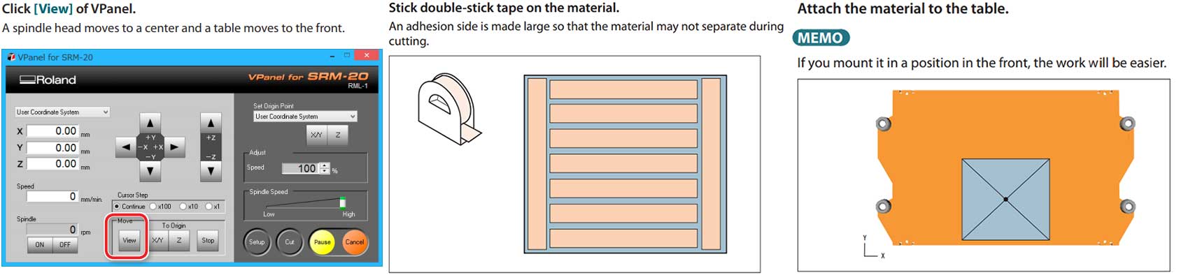
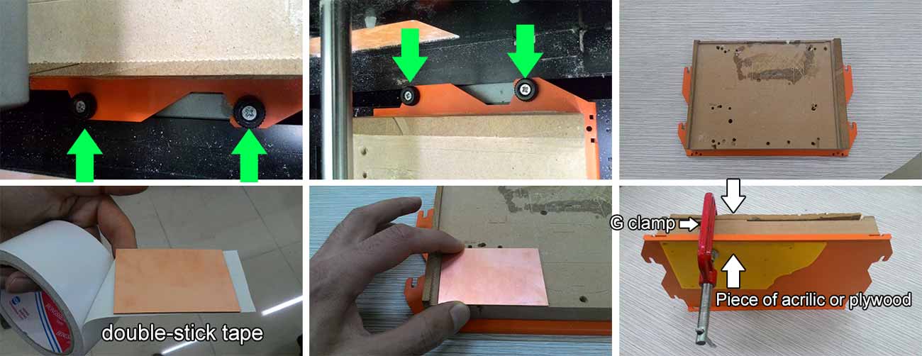
7.Attach the material to the table (image below).
My advice on this is to take out the table (unscrew 4 screws at sides) and clamp the board for 5min to increase adhision, be careful not to tighten too much this can bend the table. Put something between clamp jaws and the table to keep the board and the table safe from scratches.
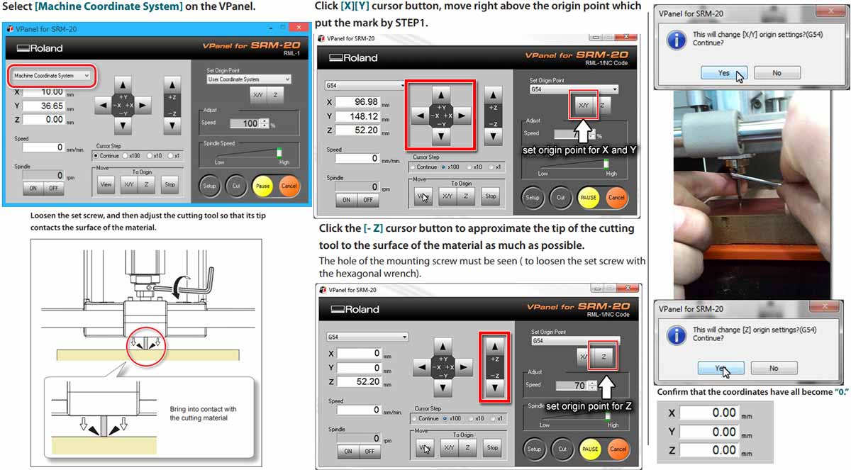
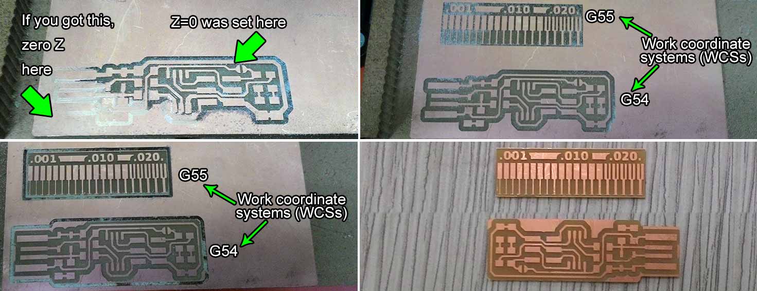
8.Set the origin point. Select [Machine Coordinate System] in our case will use G54 and G55 that's the first 2 of 6 Work Coordinate Systems. Drive the bit to desired location with [X/Y] buttons shown above, and hit [X/Y] set origin point button in the right side of the Vpanel interface shown in the picture below. Drive down the bit just a little bit above the material using the [Z] buttons shown in the picture above. Unscrew the tiny bolt that holds the milling tool in place, support the tool with your finger so it drops and touches the copper surface. Fasten the bolt, but not too hard. Once done hit the [Z] set origin point button in the right side of the Vpanel interface shown in the picture below.
Getting the cut files and generating the toolpaths.
In our case the cut files are FabtinyISP traces and FabtinyISP cutout. The toolpath is the path that our bit has to travel in order to get the desired geometry on the base material. In order to generate the "toolpath" we'll be using FabModules (image below). And after generating the toolpath we'll save it as a NC code (G-code) for the machine to understand it. Select the input file from "input format" tab, select the output from "output format" tab in our case it's G-codes (.nc) and fianlly select the tool size from the "process" tab in our case it's PCB traces (1/64).

At this point an image should appear under the selection we just did and a detailed settings on
the right
side. (image below). In "output" section you can set the
1."cut speed" (Cutting
speed) is the speed difference between the cutting tool and the
surface of the workpiece while the tool is operating on it. The units are mm/s (milimeters per
second).
2."plunge speed" is the speed at which the router bit is driven down into the
material when starting a cut and will vary depending on the bit used and the material being
processed. The units are mm/s (milimeters per second)
3."jog speed" is the speed at which the bit is driven when it's not in contact
with the material (when the bit is not cutting). The units are mm/s (milimeters per second).
4."jog height" is the height at which the router bit is driven up when it's trying to
move from one working area to another. The units are mm (milimeters).
5."spindle speed" is the speed at which the spindle is turning the bit. The units are
RPM (Revolutions per minute).
6."cut depth" is the depth which the bit will remove from the material material. The
units are mm (milimeters).
7."number of offsets" I couldn't get a precise definition for this setting, but what it
actually does it adds toolpaths near the main toolpath while adding a space between them so
the bigger the number the more times the tool will travel near the same place and eventually
remove the copper near the traces. It's default value is 4 but I tried with 5 it took slightly
more time but let less extra copper near the traces that had to be removed manually after. I
would recommend to put 6 in order get less extra copper near the traces.
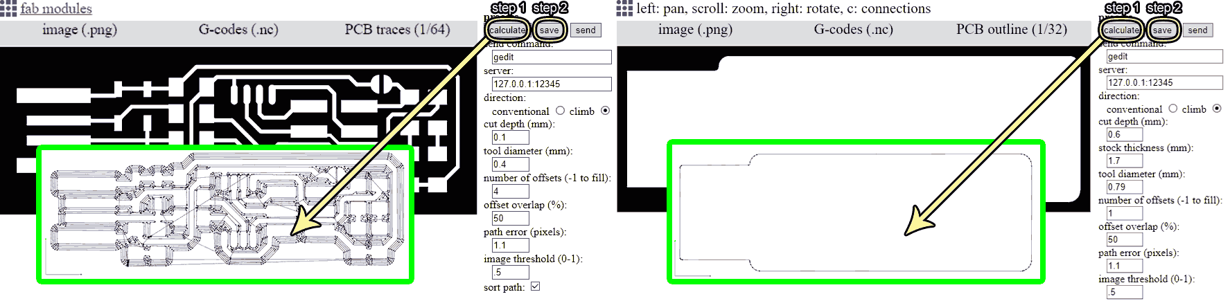
The default values work completly fine so hit "Calculate" from the right side of the interface and you'll get a toolpath like in the image above. Now save it. Now do the same thing for FabtinyISP cutout but instead of "traces 1/64" select "cutout 1/32" in the process tab of Fabmodules.org, now save it. The default Work Coordinate System of Fabmodules G-code is G54, but changing it is easier than you think. Just open the .nc file (G-code) with a text editor any will work. And find the G54 somewhere in the starting part of the code.
Cutting process
Open the V-panel make sure the 1/64 endmill is on the tool and is zeroed. Push the "cut" button from the interface hit "Delete all" to remove previous NC codes, now select the NC file you generated for the traces it's name should be "fts_mini_traces.nc" Change the speed value to 10 at the start of the cutting in order to have more time to react if something goes wrong. If everything is ok increase the speed to 100.
Soldering components
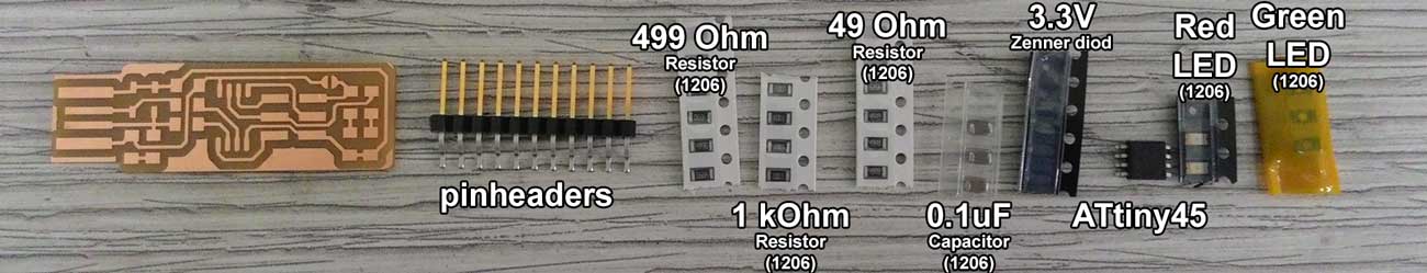
FabISP needs the following components
- 1x ATtiny45
- 2x 1k resistors
- 2x 499om resistors
- 2x 49om resistors
- 2x 3.3v zener diodes
- 2x LED
- 1x 100nF capacitor
- 1x 2x3 pin header
Programming the board
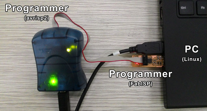
For programming the FabISP you will need
- An Ubuntu computer with 2 USB ports
- AVR programmer (in my case it was avrisp2)
- "avrdude" and "avr-gcc" installed (Need to install? go HERE)