Kidsulator
what tasks have been completed and what tasks remain?
Tasks have been completed:
- 2D & 3D Designs
- Print and cut the design
- Milling the PCB
- Soldring the PCB
- Testing the PCB
- Testing simple Math operations
Tasks remainl:
- Bill of Materials
- Testing all numbers
- compare between two options in the program
- Poster
- Video
- Finalize the assembly project
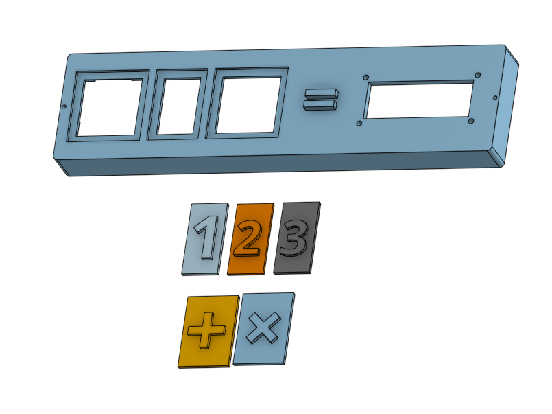
I have done an initial modeling using Onshape to start imagination the project parts and how it works!
Design and Fabrication
It relied on in the design Onshape program that was used in many of the previous assignments:
2D Design
The following image is the sketch of bottom case cut by laser cutter
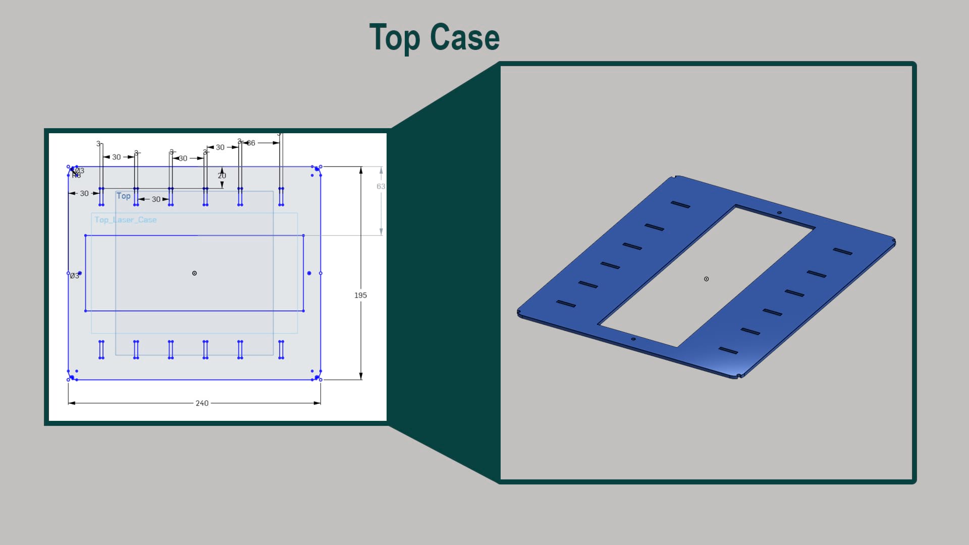
The dimensions of the top cover case which takes a hole that is going to hold top 3D print later on where the main part of the project will be install
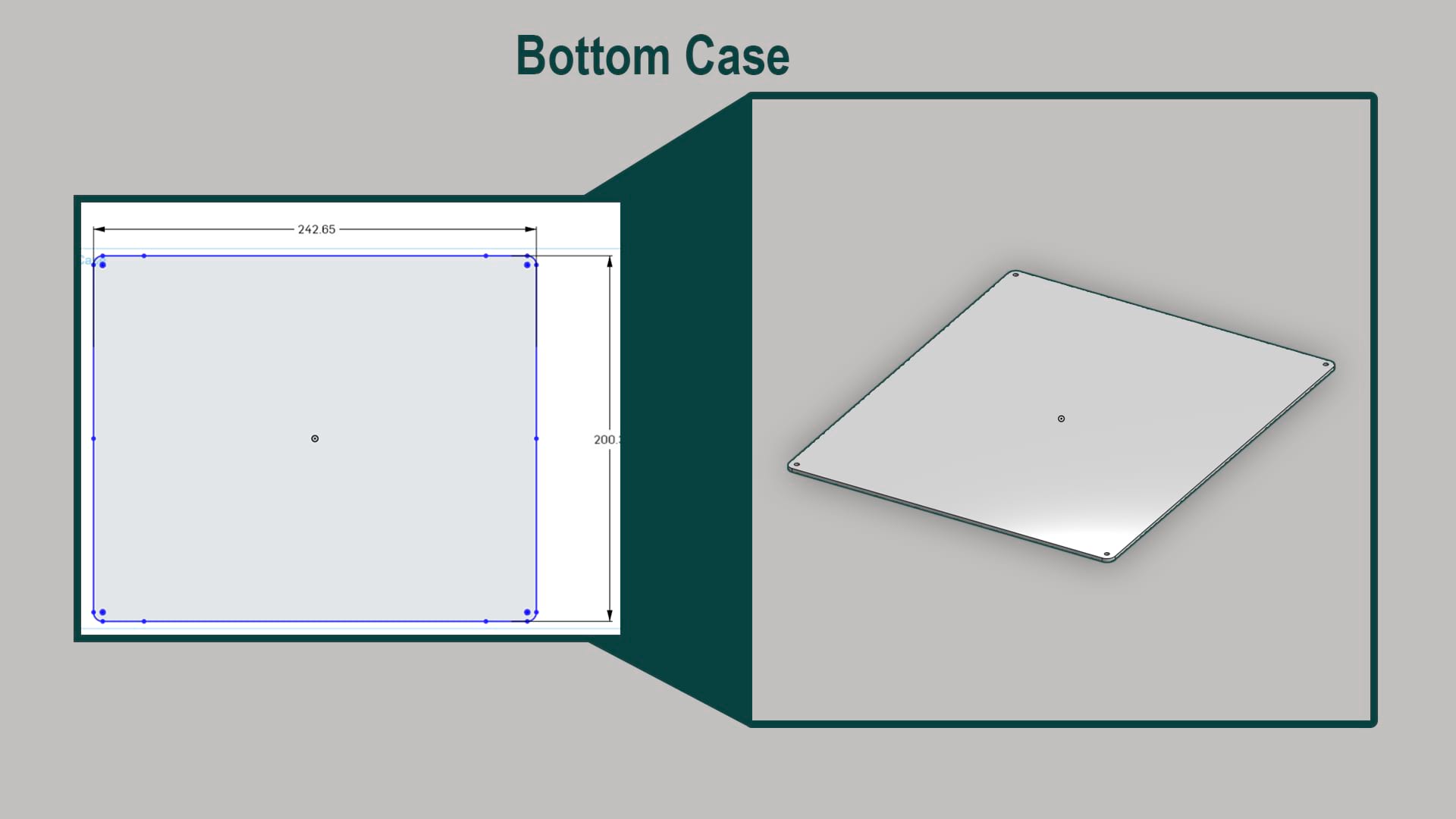
Bottome case dimensions of the case that cutting by laser cutter
A render of the case how is going to look likes
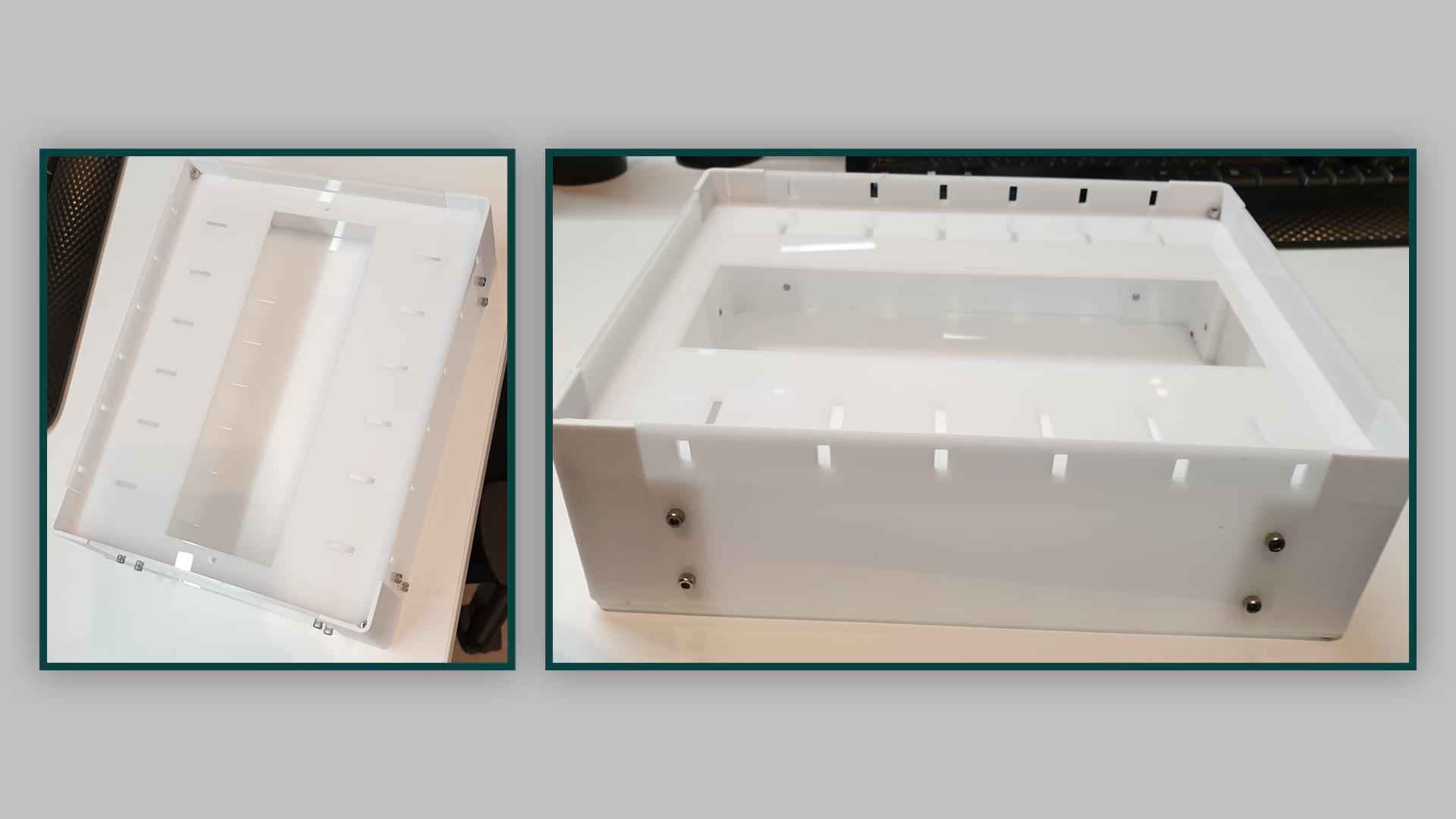
The acrylich case after assembled
_____________________________________________________________________________________________________
3D Design
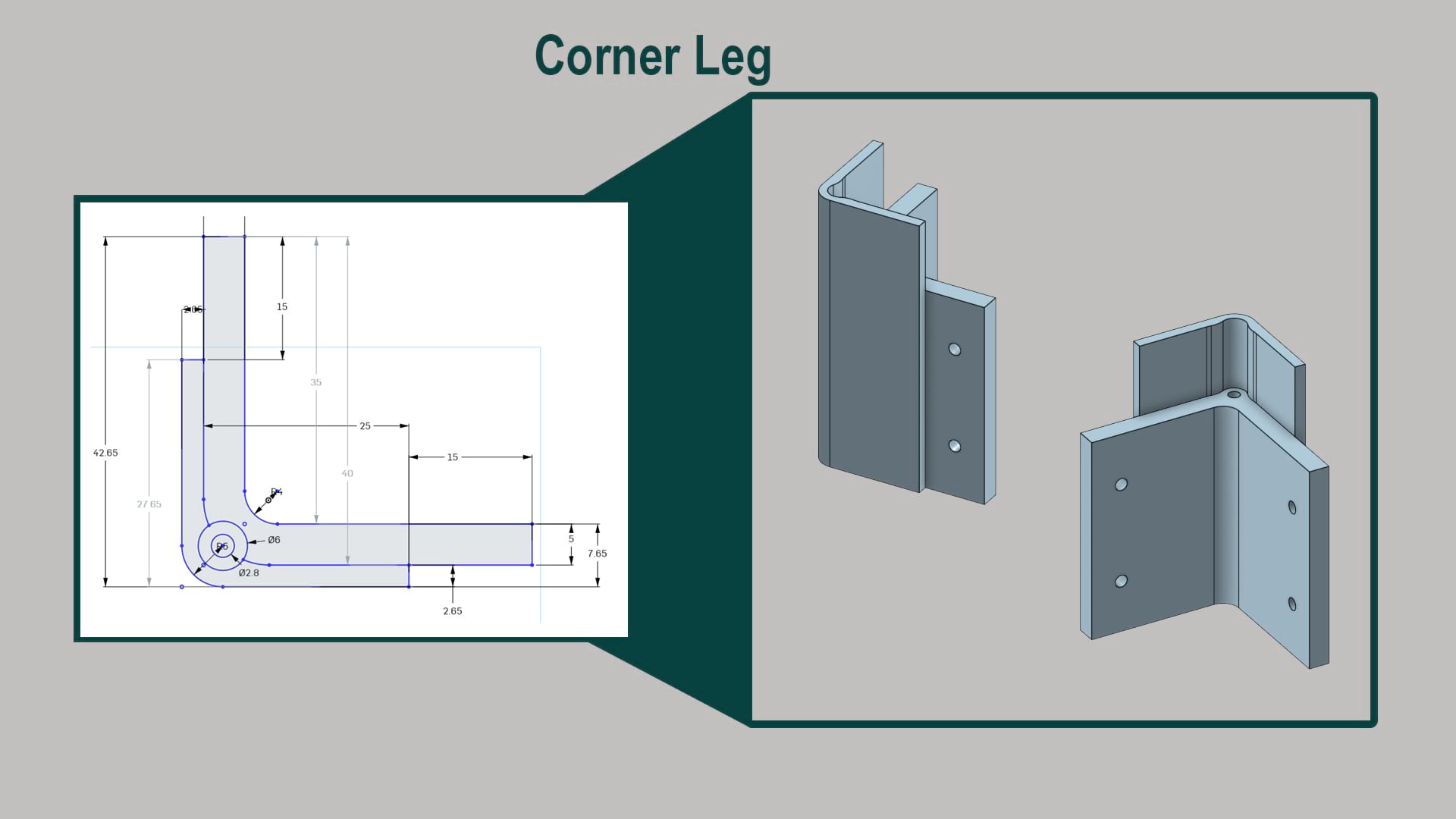
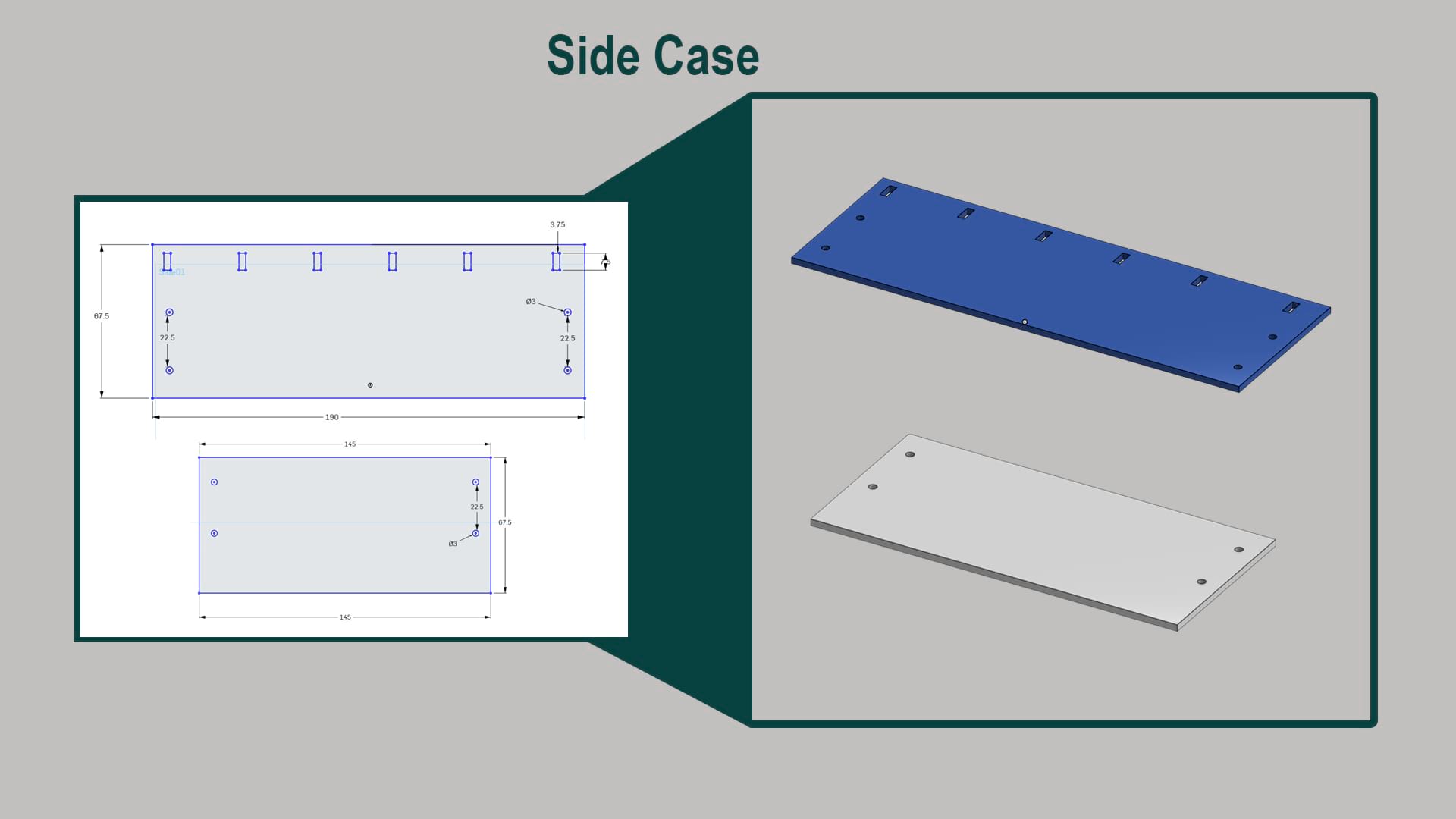
Sketching the corner leg that needs to use to build a case (box) that was cut by laser cutter in the previous section
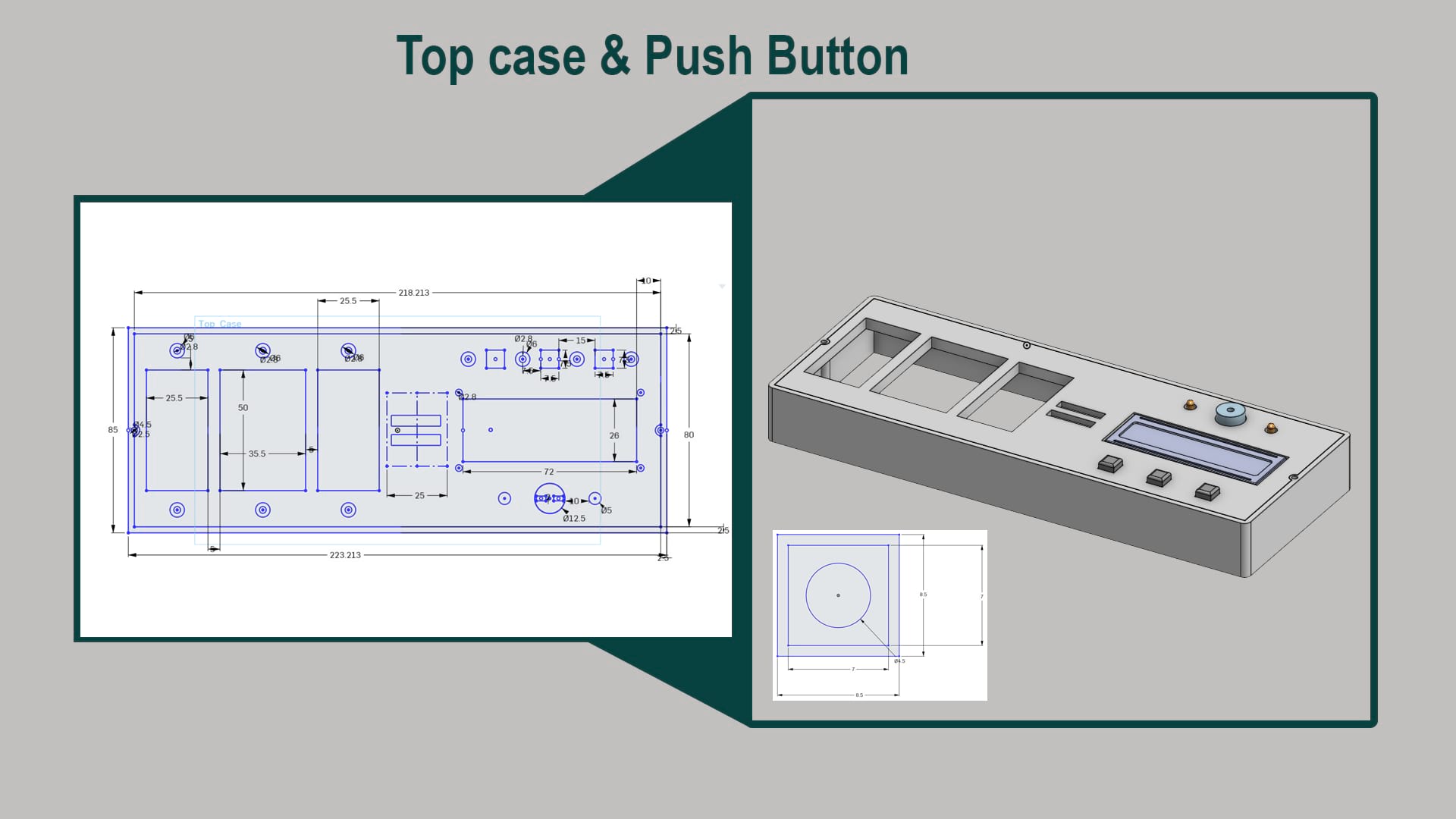
Measurements to build the top part of the project which include LCD, Push buttons and LED as well as Buzzer and the main part to add and read numbers
_____________________________________________________________________________________________________
PCB
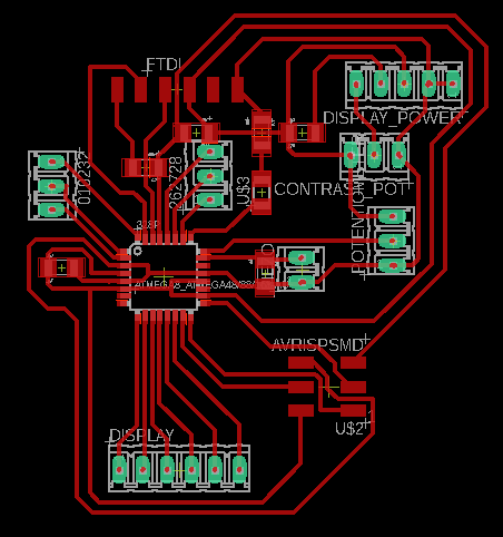
For Electronic Design, I started by modifying the satcha board, but modifying it to have an LCD, 2 LEDs and buzzer for Output, and push buttons and digital inputs to read the numbers from my final project. The general schematic and board are shown below:
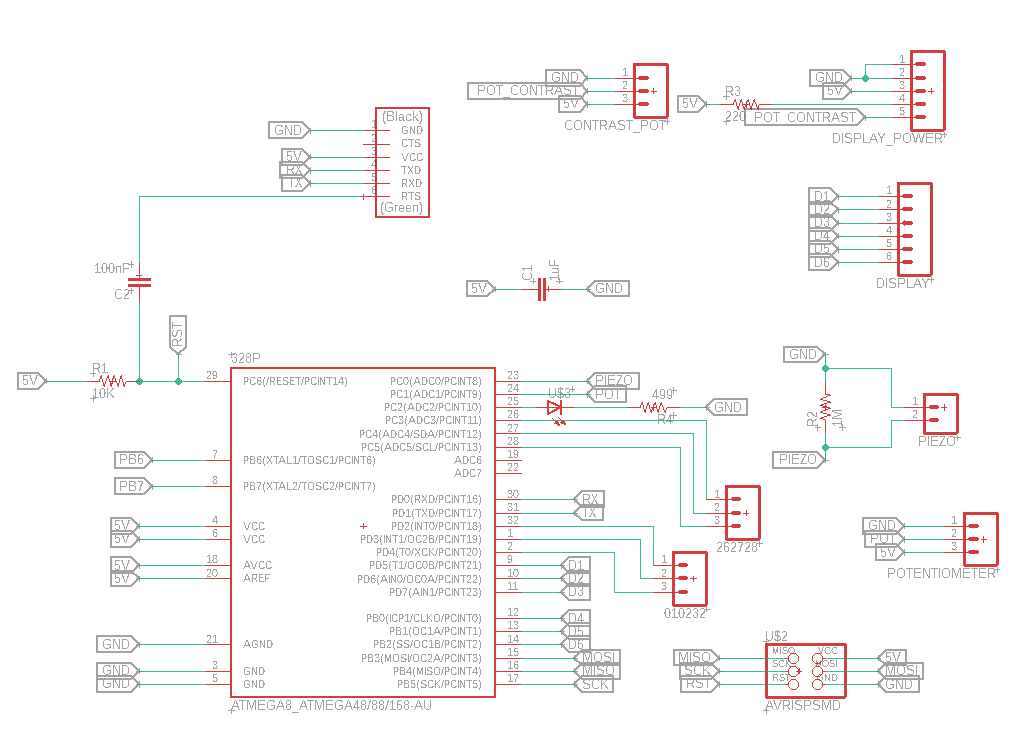
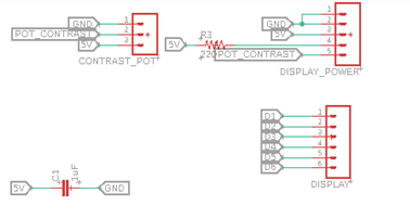
The following close-up shows the output elements
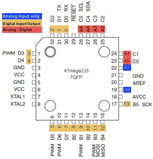
The following close-up shows the input elements. Focused on pins , 11, A2, A5, A4, A3, A1, 4, 3, 2, A0, 1, 0 and 1
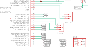
And are connected to the ATMAEGA using its pins which I found in the datasheet.
and this was the final Result.

_____________________________________________________________________________________________________
what has worked? what hasn't?
Worked:
- Simulation the operation
- Testing the PCB
- Define Pins
- Define LCD
- Initialize variables
In progress:
- Pushbuttons
- Random Operations in the screen
- Uplaod full programming to PCB
Testing and Programming
Now, to simulate the operation of my board, I used thinkercad, and simulated by numbers by using sliding switches.
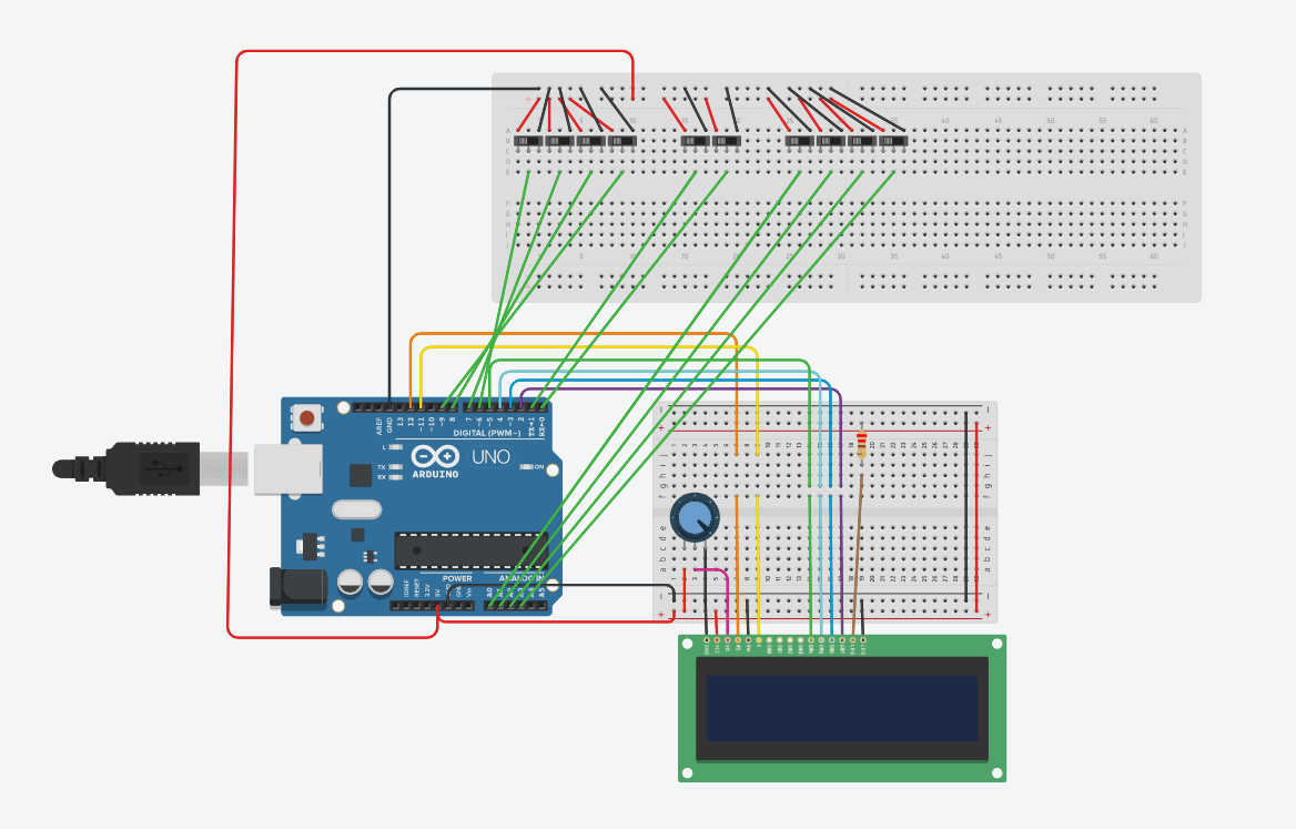
After checking that the logic of my program was working, I then started to do the connections using my board and testing for everything to work. I program by board using another arduino, and then uploaded the code which I will explain next.

I begin my code by defining the pins I’m going to use.
                        #define op1 11
  #define op0 A2
  #define x3 A5
  #define x2 A4
  #define x1 A3
  #define x0 A1
  #define y3 4
  #define y2 3
  #define y1 2
  #define y0 A0
  #define sw1 0
  #define sw2 1
and then define which pins are going to be used for the LCD display.
                      // include the library code:

#include <LiquidCrystal.h>
const int rs = 5, en = 6, d4 = 7, d5 = 8, d6 = 9, d7 = 10;
LiquidCrystal lcd(rs, en, d4, d5, d6, d7);

// initialize the library with the numbers of the interface pins
Then, I Initialize my variables:
                        char operation_sym[4] = { '+', '-', '*', '/' };
  int n1 =0;
  int n2 =0;
  int operation=0;
  int ans, r_ans;
and in the Void Setup, I define the pin modes for the pins I’m going to use, and initialize my LCD .
                      void setup() {  //Serial.begin(9600);
    pinMode(op1, INPUT_PULLUP);     //For operation
    pinMode(op0, INPUT_PULLUP);     //For operation
    pinMode(x3,  INPUT_PULLUP);     //For number 1
    pinMode(x2,  INPUT_PULLUP);     //For number 1
    pinMode(x1,  INPUT_PULLUP);     //For number 1
    pinMode(x0,  INPUT_PULLUP);     //For number 1
    pinMode(y3,  INPUT_PULLUP);     //For number 2
    pinMode(y2,  INPUT_PULLUP);     //For number 2
    pinMode(y1,  INPUT_PULLUP);     //For number 2
    pinMode(y0,  INPUT_PULLUP);     //For number 2
    pinMode(sw1, INPUT);
    pinMode(sw2, INPUT);
    pinMode(12, OUTPUT); //For number  2
    // set up the LCD's number of  columns and rows:
    lcd.begin(16, 2);
    //randomSeed(analogRead(0));
  }
Method Calculate just returns the answer of the operation, which could be add, subtract, multiply or divide, depending on the inputs for operation,
                      //CALCULATE THE OPERATION DEPENDING ON THE INPUT  0 AND 1. 00=/ 01=* 10=- and 11=+
  int calculate ( int x, int y, int operate)
  {
    if (operate == 0){
        return x+y  ;
      }
      else if (operate ==  1){
        return x-y  ;
      }
    else if (operate == 2){
        return x*y  ;
      }
      else if (operate ==  3){
        return x/y  ;
      }
  }
In task 2, I will display a random operation in the screen, and the student needs to select the correct answer and place it in the slot. For this, I generate a random operation, from 0to4, and 2 random numbers from 0 to 9. Internally, I calculate the answer, and then wait for the student to place the tile of the answer he thinks is true. I wait until the correct answer is placed in order to exit the while, and the turn on the LEDs and buzzer, meaning they got the right answer.
                          void task2()
    {
    lcd.clear();
    lcd.print("Solve Me");
    operation = random(3);
    n1 = random(9);
    n2 = random(9);
    r_ans =  calculate(n1,n2,operation);
    lcd.setCursor(3, 1);
    lcd.print("=");
    lcd.print(r_ans);
    while ( true )
    {
      read_();
      if(n1!=0) // check if  there is a number
      {
        if(n1==10)
          n1=0;
        lcd.setCursor(0,  1);
        lcd.print(n1);
      }
      if(n2!=0)
      {
        if(n2==10)
          n2=0;      lcd.setCursor(2, 1);
        lcd.print(n2);
    }
      lcd.setCursor(1, 1);
      lcd.print(operation_sym[operation]);
    ans =  calculate(n1,n2,operation);
      if (ans == r_ans)
      {
        return;
      }
    }
  }
what questions need to be resolved?
Questions:
- Is the PCB has enough pins?
- Is the PCB will be able to read complexity program and numbers?
- Adding to options program and selecting by pushbuttons?
What will happen wen?
Questions:
- Finialize the project?
- Make the project nicely look
Note: the project plan targeting when everything will be ready take a look down the page.
What have you learned?
I learned:
- More flexibility to soldering the PCB
- Get new knowledge in 3D Modeling instead of 2D sketching and that appeared in the final project design
Project Management
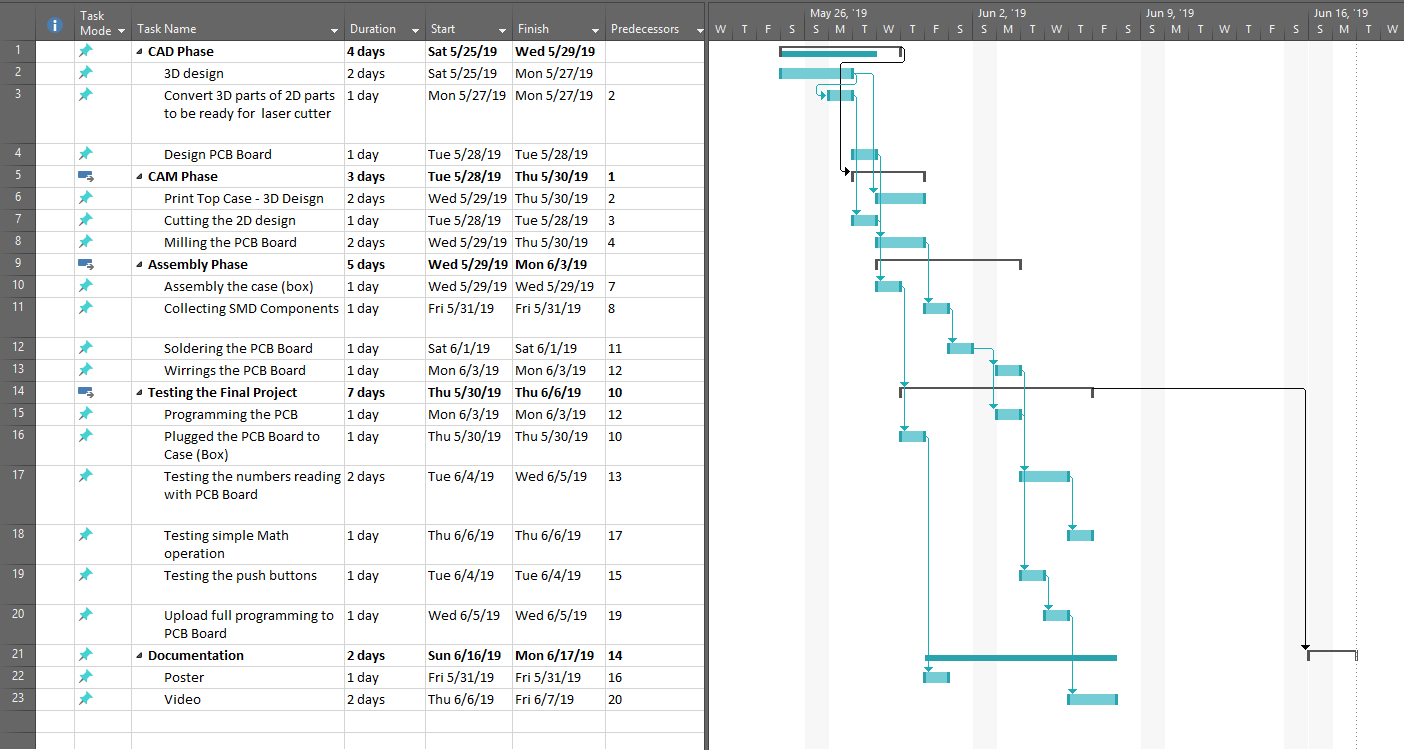
This documentation and project plan is answering the following points
:
- Triage
- Documentation during development
- Demand - vs supply-side time management
- Spiral development
- Serial vs parallel tasks
- System integration
- Finish Quality