18. Wild Card Week
One thing that was never greatly talked about, only briefly, was power considerations. It was briefly mentioned during output device week, but given everything else we were trying to handle that week, it kind of got overshadowed.
Part of the inspiration behind exploring power was derived from the DC motot board, with the larger traces on the input coming in. Given my background in engineering, I understood that the larger amperage required to drive the motor dictated a larger cross sectional area for the additional electricity to flow. I was also interested in looking at how we can power devices with a solar panel.
Solar Chargers
Solar powered phone chargers are popular items, given how central phones are to our everyday lives. I decided to do a little bit of research to see what we could in order to make our own in a Fab Lab.
There were a couple options to consider - hooking up more power than needed and stepping down (like here), or using less and stepping up. The 2nd option seems ideal, especially for a solar charger, for two reasons. First, it is more efficient. The typical large batteries that would be used are 9 V, which tend to be really inefficient when it comes to current. They have a high internal resistance that really dampers everything, especially with the newer phones that demand more current to charge. Secondly, given the emphasis here on solar power and inconsistencies that may occur with that, it would be better to have the option to increase everything instead.
It’s important to note how the boost converter works - the datasheet for the part and Wikipedia both have good summaries of it. Basically, it keeps the power level constant and sacrifices current for voltage. It uses a transistor and a diode to direct the increased voltage, employs capacitors to act as filters on the load and supply sides, and uses a capacitor and/or an inductor (coil) as an energy storage medium to aid it. In short, there is an internal switch that cycles fast enough so that the inductor never fully loses its charge as the magnetic field is created and destroyed, resulting in it having a higher electrical potential than the input.
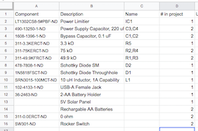
Adafruit has the plans for their Minty Boost charger, which we can reverse engineer to design on our own and save some money on it! So that can take us from 2.4 V (2 AA batteries) to the 5 V required for USB charging. We can also throw in a solar panel though, to save on the battery life. The boost can take an input up to 10 volts, so we can also include a 5 V or so solar panel and not worry about frying anything. The datasheet also does a great job of explaining the mechanism and circuit requirements that we saw in the Adafruit system. So let’s get to it!
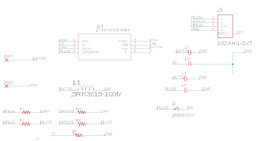
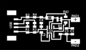
So there it is! Pretty straightforward to make, and it is important to combine the positive leads coming off of the solar panel and battery holder through switches, so we can turn everything on and off. Also, I put a diode coming off of the solar panel so we don’t fry it.
In terms of production, the boost was easy to fry if you weren’t careful when soldering, so that was frustrating at times. If I had to redo the circuit I would probably include LEDs to show what was on. Oh well!
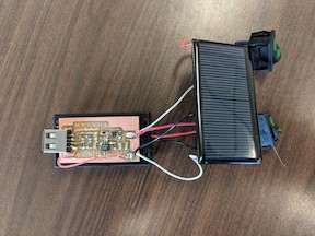
Now let’s see how it works.
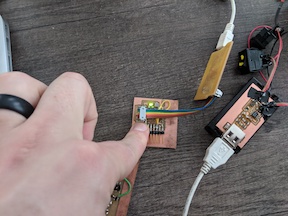
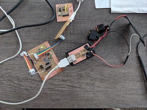
Great! It even works to power our boards via a USB and the FabISP.
Going further, there are multiple options that are able to output even more voltage than the 5 V. Those could be useful for certain projects that can be made, especially since motors require a larger output than USB power can provide and more amperage than 9 V provide. Of course MOSFETs can also work, but this would lead to a more consistent output that a motor may require.
It could also be worthwhile to make a protective case for the charger, so it doesn’t get ripped apart in your pocket. Not that that ever happened to me, nope no way no how.